Page 363 of 1395

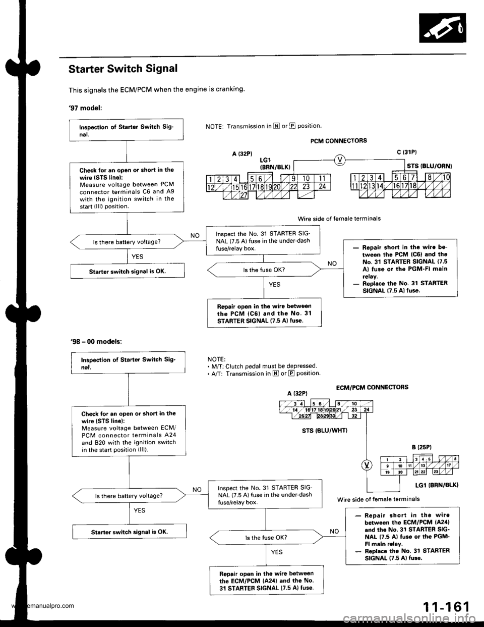
Starter Switch Signal
This signals the ECM/PCM when the engine is cranking.
'97 model:
A {32P}
'98 - 00 models:
Transmission in E or E position.
LGl(BBN/BLK)
PCM CONNECTORS
Wire side of female terminals
ECM/PCM CONI{ECTORS
STS (BLU/ORNI
c t31P)
NOTE:. M/T: Clutch pedal must be depressed.. A/T: Transmission in E orE position
Check for an opan ot short in the
wire (STS linel:Measure voltage between PCM
connector terminals C6 and Ag
with the ignition switch in the
start (lll) position.
lnspect the No. 31 STARTER SIG-
NAL (7.5 A)Illse in the under'dashls there battery voltage?- Reoair short in the wire be-
tween the PCM lc6l and th.No. 31 STARTER SIGNAL 17 5A) tuse ot the PGM-FI main
reray.- Reolace the No. 31 STARTERSIGNAL t7.5 Altu.e.
Starter swiich signal i3 OK.
Repair opon in the wire betweonrh6 PCM lc6l and the No 31
STARTER SIGNAL 17.5 A)fuse.
A (32P)
Wire side oI female terminals
Check tor an open or short in thewir€ (STS line):Measure voltage between ECM/
PCM connector terminals A24
and 820 with the ignition switchin the start position (lll).
Inspect the No. 31 STARTER SIGNAL (7.5 A){use in the under-dashls there battery voltage?
- Reoair shorl in the wire
betwe€n the ECM/PCM lA2,fland the No, 31 STARTER SIG-NAL t7.5 Al tu3€ ot the PGM'Fl main rclay.- Repl.c. tho No. 31 STARTERSIGNAL 17.5 Al fu3e.
Starter switch 3ignal is OK.
Repair opon in tho wire between
the ECM/PCM {A241 and the No
31 STARTER SIGNAL (7.5 A) tu3e
1 1-161
www.emanualpro.com
Page 365 of 1395
{From page 11 162)
PCM CONNECTORS
Wire side of female terminals
c t3lPl
Check for a short in the PSP
swilch:1. Turn the ignition switch OFF.2. Disconnect the 2P connectorfrom the PSP switch.3. Turn the ignition switch ON (ll).
4. lleas u re voltage betweenPCM connector terminals C16and A9.
Check tor a short in the wire (PSP
SW linol:1. Turn the ignition switch OFF.2. Disconnect PCM connector C(31P).
3. Check for continuity betweenbody ground and PCM connec-tor terminal C16.
Reoair short in the wire betwoonrhe PCM {C16) and the PSP3witch.
Substitute a known-good PCM
and rocheck. lf proscribod volt-age b now available, replace theoriginal PCM.
(cont'd)
-16311
www.emanualpro.com
Page 366 of 1395

ldle Control System
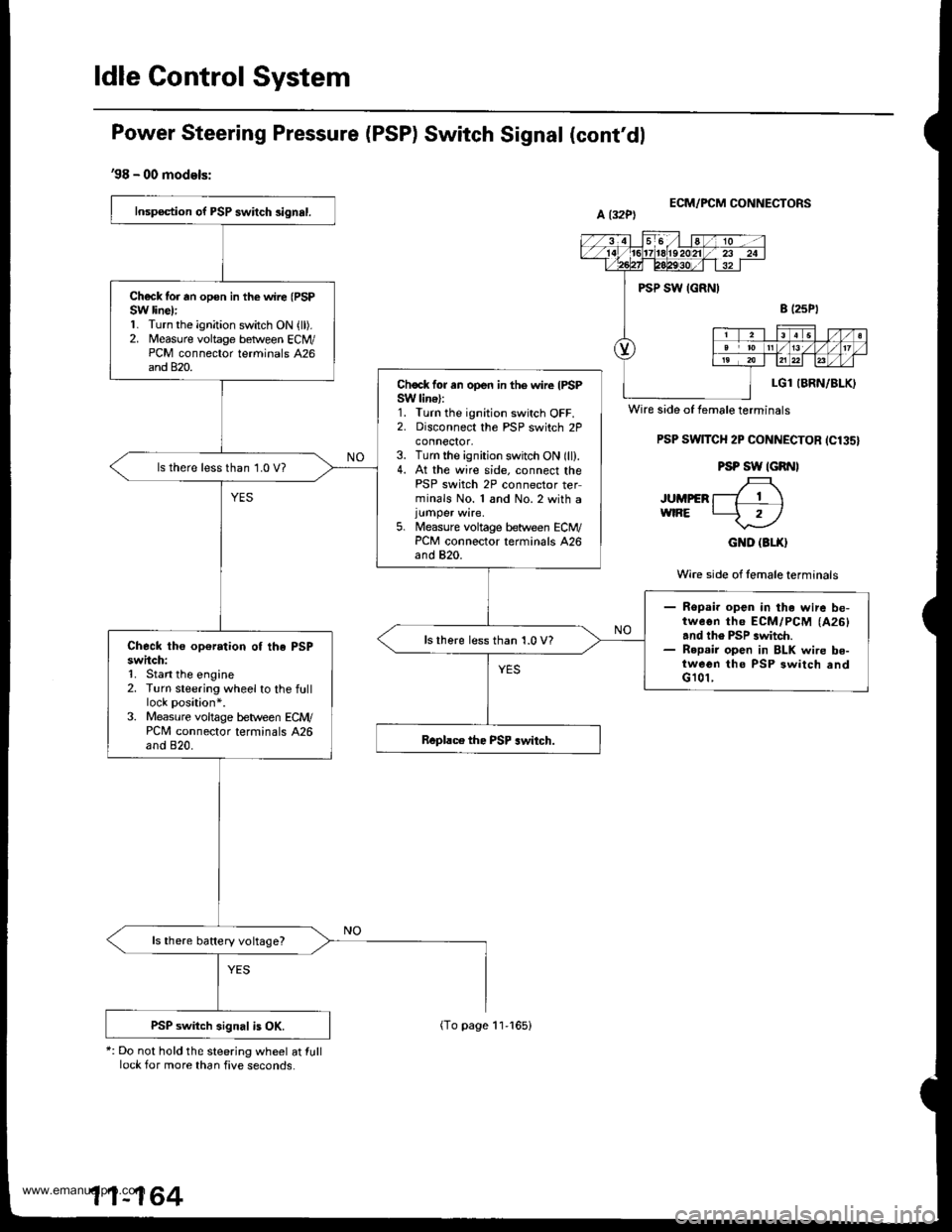
Power Steering Pressure (PSP) Switch Signal (cont'dl
'98 - 00 models:
*: Do not hold the steering wheel at lulllock for more than five seconds.
ECM/FCM CONNECTORS
PSP SwlTCH 2P CONNECTOR ICl35}
PSP SW IGRNI
JUMpER f-7 T \wtRE L-5 rl
GND (3LX}
Wire side of lemale terminals
Inspection of PSP swilch 3ignal.
Ch€ck tor rn opon in the wire (PSP
SW line):1. Turn the ignition switch ON {ll).2. Measure voltage betlveen ECM/PCM connector terminals 426and 820.
Chock for an open in the wire IPSPSW lin€):1. Turn the ignition switch OFF.2. Disconnect the PSP switch 2Pconnector,3. Turn the ignition switch ON (ll).4. At the wire side. connect thePSP switch 2P connector terminals No. 1 and No.2 with a
5. Measure voltage between ECM/PCM connector terminals 426and 820.
ls there less than 1.0 V?
- Ropai. open in the wire be-tweon th6 ECM/PCM (A26)
and th6 PSP .witch.- R6p.ir open in BLK wire be-tween tho PSP 3witch andG 101,
lsthere less than 1.0 V?Check the op€ration of the PSPswitch:1. Stan the engine2. Turn steering wheel to the fulllock position*.3. Measure voltage b€tween ECM/PCM connector terminals A26and 820.
ls there battery voltage?
PSP switch signal is OK.
Wire side of female terminals
11-164
(To page 11-165)
www.emanualpro.com
Page 367 of 1395
{From page 11 164i
Check for a short in the PSPswitch:1. Turn the ignition switch OFF.2, Disconnect the 2P connectorfrom the PSP switch.3. Turn the ignition switch ON (ll).
4. Measure voltage betlveen ECM/PCM connector terminals A26and 820.
Check lor e 3hort in the wire IPSPSW linell1. Turn the ignition switch OFF.2. Disconnect ECM/PCM con-nector A (32P).
3. Check for continuity betweenbody ground and ECM/PCMconnector terminal A26.
ReDair short in the wir€ bstweenthe ECM/PCM (A26) and the PSPswitch.
Substitute a known-good ECM/PCM and rechock. It Drescribodvoltago is now available, roplacethe origin.l ECM/PCM,
ECM/PCM CONNECTORS
A l32Pl
Wire side of female terminals
Wire side of female terminals
1 1-165
www.emanualpro.com
Page 368 of 1395
ldle Control System
Brake Switch Signal
This signals the ECM/PCM when the brake pedal is depressed.
('97 model)'- - - - -_- Il
PCM CONNECTORSa t32P) D ll6Pl
BKSW(GRN/WHT)
Wire side of female terminals
Insp€ction of Brak. Switch Signal.
Are the brake lights on withoutpressing the brake pedal?
Inspect the HORN, STOP {15 A)fuse in the undeFhood luse/ relaybox.Do the brake lights come on?
Reoair short in the wire be-tween th€ b.ake switch andth6 HoRN, STOP {15 A)luso,Replaco the HoRN, STOP (15
Al fuse.
Repair op6n in the wir€ be-tween the brake switch andtho HORN, STOP (15 Allus6.Inspect the brrke switch (see
aection l9l.
Check tol .n open in the wire{BXSW linel:1. Press the brake pedal.2. Measure voltage between rcMconnector terminais D5 and Agwith the brake pedal pressed.
Reprir open in the wire betweenthe PcM lD5l rnd the brakeswitch.
(To page 11-167)
1 1-166
www.emanualpro.com
Page 372 of 1395

ldle Control System
ldle Speed Setting (cont'd)
38 - 0O mod6l3:
NOTE: Before setting the idle speed, check the follow-
ing items:- The MIL has not been reported on.- lgnition timing- Spark plugs
- Air cleaner- PCV system
1. Start the engine. Hold the engine at 3.000 rpm with
no load (in Park or neutral) until the radiator fan
comes on, then let it idle.
Connect a tachometer.
Disconnect the IAC valve 2P connector and the EVAP
purge control solenoid valve 2P connector.
CONTROLSOLENOID VALVE
SOLENOID VALVE
lf the engine stalls, restart the engine with the accel-
erato. pedal slightly depressed. Stabilize the rpm at
1,000, then slowly release the pedal until the engine
idles.
Che€k the idle in no-load conditions: headlights, blow-
er fan, rear defogger, radiator fan, and air conditioner
are not operating,
ldle speed should bo:
480 t 50 rpm {in PErk or noutrall
11-170
lf necessary, adjust the idle speed, by turning the
idle adjusting screw.
After adjusting the idle speed, recheck the ignition
timing (see section 4). lf it is out of spec, go back to
steo 4.tDt.E
6. Turn the ignition switch OFF.
7. Reconnect the 2P connectors to the IAC valve and
the EVAP purge control solenoid valve, then do the
ECM/PCM reset procedure.
8. Restart and idle the engine with no-load conditions
for one minute, then check the idle speed.
ldle speod should be:,98 model:
750 t 50 rpm tin Park or neutral)'9!l - 00 modsls:
730 i 50 lpm lin Psrk or neutral)
NOTE: lf the idle speed increases to 780 t 50 rpm(770 1 50 rpml*, this means the EVAP system is
purging the canister. To stop the purging temporari-
ly, raise the engine speed above 1,000 rpm with the
accelerator pedal, then slowly release the pedal.*: '99 - 00 models
9. Let the engine idle for one minute with the head-
lights (Low) ON, and check the idle speed.
ldle speed should be:
38 mod6l:
750 f 50 rpm (in Palk or neutrall'99 - 00 modols:
730 t 50 rpm (in Palk or neutral)
10. Turn the headlights off. Let the engine idle for one
minute with the heater fan switch at Hl and air con-
ditioner on, then check the idle speed.
ldls spqed should be:'98 model:
780 t 50 rpm (in Park or neutrall'99 - 00 mod€ls:
7701 50 rpm lin Park or neutral)
lf the idle speed is not within specification. see the
Symptom Chart on page 11-64.
ADJUSTING
www.emanualpro.com
Page 381 of 1395
Fuel Injectors
R6placomoni
1. Relieve the fuel pressure (see page 11-178).
2. Remove the resonato. chamber ('99 - 00 models).
O.RINGBeplace.
Disconnect the connectors from the fuel injectors, and disconnect the IAT sensor 2P connector ('97 - 98 models) and
EVAP purge control solenoid valve 2P conn€ctor ('97 - 98 models),
Disconnect the PCV valve and the vacuum hose from the fuel pressure regulator.
Place a shop towel over the fuel return hose, then disconnect it from the fuel pressure regulator.
Remove the retainer nuts on the fuel rail.
Disconnect the fuel rail.
7, Remove the fuel injectors from the intake manifold.
'97 - 98 model3:
EVAP PURGE CONTROLSOLENOID VALVE 2P CONNECTORIAT SENSOR
FUEL PULSATION2P CONNECTOR
12 N.m{1.2 kgt'm,8.7 tbtft)
FUELPRESSUREREGULATOR
O.RING
FUELPRESSUREREGULATOR
CUSHION
O.RINGReplace.
CUSHIONRINGReplace.
SEALRINGReplace.
Replace.
SEALRINGReplace.
S
11-179
www.emanualpro.com
Page 382 of 1395

Fuel Supply System
Fuel Injectors {cont'dl
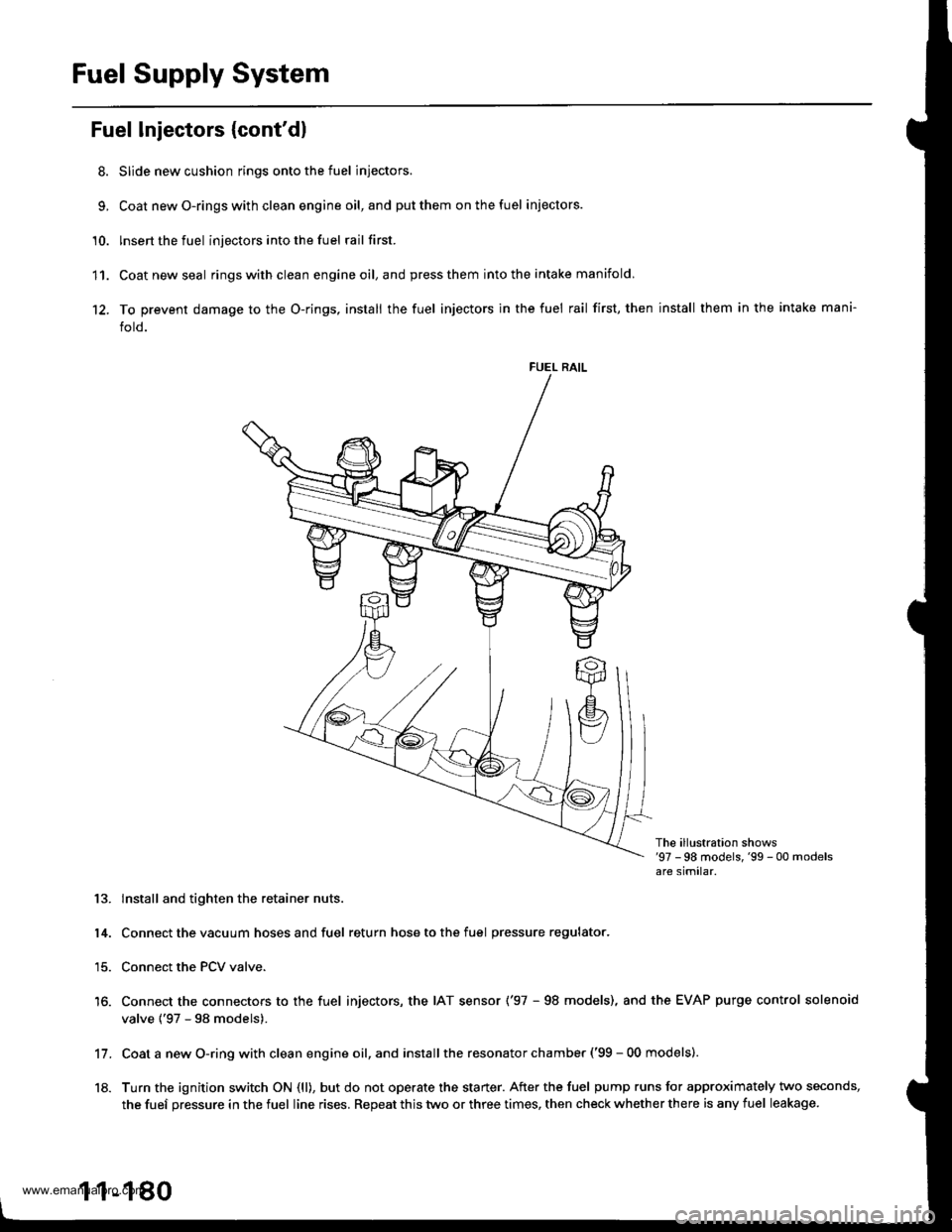
8. Slide new cushion rings onto the fuel injectors.
9, Coat newO-ringswith clean engine oil,and putthem onthefuel iniectors.
'10. lnsert the fuel injectors into the fuel rail first.
11. Coatnewseal ringswithclean engineoil,and press them into the intake manifold
12. To prevent damage to the O-rings, install the fuel injectors in the fuel rail first, then install them in the intake mani-
fold.
FUEL RAIL
The ill!stration shows'97 -98 models,'99 - 00 modelsare similar.
13. lnstall and tighten the retainer nuts.
14. Connect the vacuum hoses and fuel return hose to the fuel pressure regulator.
15. Connect the PCV valve.
16. Connect the connectors to the fuel injectors, the IAT sensor ('97 - 98 models), and the EVAP purge control solenoid
valve {'97 - 98 models).
Coat a new O-ring with clean engine oil, and install the resonator chamber ('99 - 00 models).
Turn the ignition switch ON (ll), but do not operate the starter. After the fuel pump runs for approximately two seconds,
the fuef pressure in the fuel line rises. Repeat this two or three times, then check whether there is any fuel leakage.
11.
18.
1 1-180
www.emanualpro.com