Page 836 of 1395
4. Seat the external circlip in the groove of the inter-
mediate shaft.
Press
+ DRNER07749 - 0010000
Pack the interiorof the outer seal.2.0- 3.5 9 {0.07 - 0.12 oz)
OUTER SEAL
ATTACHMENT,52x55mm07746- 0010400
ATTACHMENT.40 x 50 mm l.D.07LAD - PW50601EXTERNALCIRCLIP
6.
Install the outer seal into the bearing support using
the special tools. The seal should be flush with the
bearing support.
Install the new set ring in the intermediate shaft
groove.
lnstallation
1. Clean the areas where the intermediate shaft con-
tacts the transmission (differential) thoroughly with
solvent or carburetor cleaner, and dry with com-
pressed air. Insen the intermediate shaft assembly
into the differential. Hold the intermediate shaft hor-
izontal to prevent damage to the differential oil seal.
2. Install the three dowel bolts, then torque them.
OOWEL BOLTS10 x 1.25 mm39 N.m {4.0 kgf.m, 29 lbtftl
INTERMEOIATE SHAFT
16-21
www.emanualpro.com
Page 843 of 1395
Rear Driveshafts
Reassembly (cont'd)
18. Install the new set ring into the driveshaft groove.
SET RINGReplace.
I
CI
SET RING GROOVE
16-2A
lnstallation
'1. lnstall the outboard joint into the trailing arm.
Install the rear driveshafts into the rear differential
assembly (see section 15).
Apply a small amount of engine oil to the seating
surface of the new spindle nut.
SPINDLE NUT 22 x 1.5 mm181 N.m (18.5 kgf.m, 134lbl.ftl Replace.
Install a new spindle nut, then torque the nut. After
tightening, use a drift to stake the spindle nut shoulder
against the driveshaft.
Clean the mating surfaces of the brake disc and the
wheel, then install the rear wheel, and torque the
wheel nuts.
WHEEL NUT 12 x 1.5 mm108 N.m (11.0 kgt.m, 80lbtftl
www.emanualpro.com
Page 845 of 1395

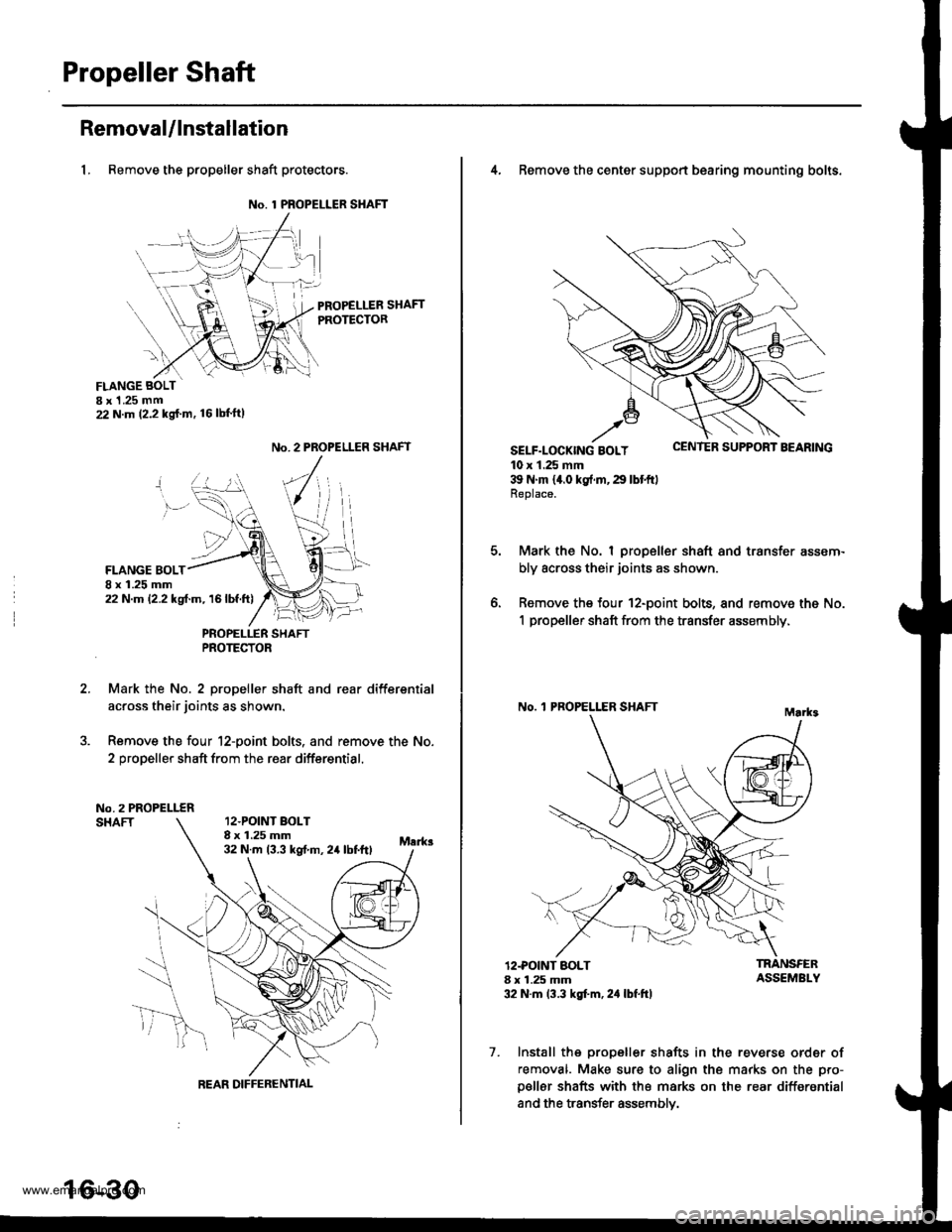
Propeller Shaft
RemovaUlnstallation
1, Remove the propeller shaft protectors.
No. 1 PROPELLER SHAFT
PROPELLER SHAFTPROTECTOR
FLANGE BOLTI x 1 .25 mm22 N.m (2.2 kg{.m. 16lbl'ft)
2.
No. 2 PROPELLER SHAFT
FLANGE BOLT8 x 1.25 mm22 N.m 12.2 kgf.m, 16lbf.ft)
PNOPELLER SHAFTPROTECTOR
Mark the No. 2 propeller shaft and rear differsntial
across their joints as shown.
Remove the four 12-point bolts. and remove the No.
2 propeller shaft from the rear differential.
No.2 PROPELLERSHAFT12.POINT BOLT8 x 1.25 mm32 N.m 13.3 kst m, 24 lbtftl
REAR DIFFERENTIAL
16-30
4, Remove the center support bearing mounting bolts.
SELF-LOCK|NG BOLT uErr rEn Durrr.r'r I I'EAnrNu
10 x 1.25 mm39 N'm 14.0 kg{.rn,29 lbtftlReplace.
Mark the No. I propeller shaft and transfer assem-
bly across their joints as shown.
Remove the four 12-point bolts, and remove the No.
1 propeller shaft from the transfer assembly,
No. 'l PROPELLER SHAFT
o.
12.POINT BOLT8 x 1.25 mm32 N.m 13.3 kgt'm, 2,1 lbf.ft)
TRANSFERASSEMBLY
7. Install the propeller shafts in the reverse order of
removal. Make sure to align the marks on the pro-
p€ller shafts with the marks on the rear differential
and the transfer assemblv.
www.emanualpro.com