Page 605 of 1395
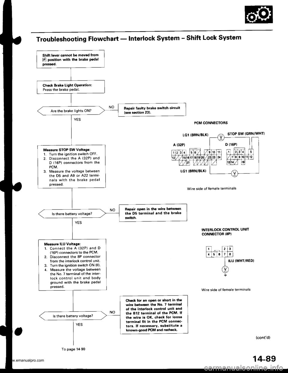
Troubleshooting Flowchart - Interlock System - Shift Lock System
PCM CONNECTORS
Wire side of lem6le termanals
INTERLOCK CONTROL UNIT
CONNECTOR I8P)
ILU IWHT/REDI
(cont'd)
Shift lever cannot be moved from
E] position with the brake P€delpreiseo.
Chock Brake Light Operation:Press the brake pedal.
Repsir fauhy brake switch circuit
{seo s€ction 231.Are the brake lights ON?
M€asure STOP SW voltage:l� Turn the ignition switch OFF.
2. Disconnect the A (32P) and
D (16P) connectors lrom thePCM.3. Measlre the voltage between
the D5 and Ag or A22 terma
nals with the brake Pedalpressed,
Repair opon in the wi.e be{w.enthe D5 terminal and the br.ke
switd!.
Measur€ ILU vohage:1. Connect the A {32P) and D
116P) connectors to the PCM.2. Disconnect the 8P connectorfrom the interlock control unit
3. Turn the ignition switch ON (ll).
4. Measure the voltage betweenthe No.7 terminalofthe inter
lock control unit and bodyground with the brake Pedalpressed,
Ch€ck for an opon or thon in the
wire Mwoon tho No. 7 terminrl
of the inte ock control unit and
the 812 termin.l of the PcM. ll
the wirs is OK, check tor loo3e
terminal fit in the PCM connec_
to13. ll nece3sary,3ubstitute a
known-good PCM and rechock.
ls there battery voltage?
To page 14 90
14-89
www.emanualpro.com
Page 606 of 1395
Electrical Troubleshooting ('97 Model)
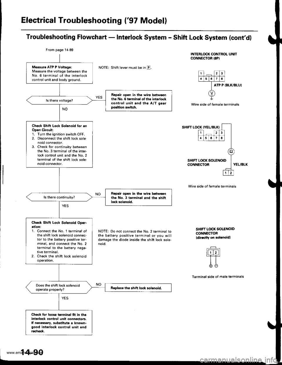
Troubleshooting Flowchart - Interlock System - Shift Lock System (cont'd)
INTERLOCK CONTROL UNITCONNECTOR {8P)
NOTE: Shift lever must be in E.
ATP P IBLK/BLU'
Wire side ot female terminals
SHIFT LOCKIYEL/BLK}
12
5678
o
LOCK SOLENOID
1
SHIFT LOCK !CONNECTORYEL/BLK
NOTE: Do not connect the No. 2 terminal tothe battery positive terminal or you willdamage the diode inside the shift lock sole-noid.
Wire side of female terminals
SHIFT L@K SOI.ENOIDCONNECTOBldir.sily on .olrnoidl
Terminalsido of male terminals
From page 14.89
Measu.e ATP P Voltage:Measure the voltage between theNo. 6 terminal of the interlockcontrol unit and body ground.
Repai. open in the wir6 betwoentho No.6 termin.l olthe intorlockcontrol unit and the A/T gealpo.ition rwitch.
Chock Shitt Lock Solenoid lor .nOpon Circuit:1. Turn the ignition switch OFF.2. Disconnect the shift lock solenoto connoctor.3. Check for continuity betweenthe No. 3 terminal of the inter-lock contrcl unit and the No. 2terminal ot the shift lock sole-noid connector.
Rapair opon in the wiro bstwcentho No. 3 torminal and tho shiftlock solenoid.
Check Shift Lock Solenoid Oper-ation:'1. Connect the No. 1 terminal ofthe shift lock solenoid connec-tor to the battery positive terminal. and connect the No. 2terminal to the battery nega-tive terminal.2. Chock the shift lock solenoidoperation.
Does the shift lock solenoidop€rate properly?Replsc€ tho .hift lock solonoid.
Check tor looso terminal frt in th6interlock cont.ol unit connectoB.ll ngcara,lary, sutEtitut€ a known-good interlock control unit androcheck.
www.emanualpro.com
Page 607 of 1395
![HONDA CR-V 2000 RD1-RD3 / 1.G Workshop Manual
Troubleshooting Flowchart - Interlock system - Key Interlock system
IGNITION SW]TCH 6P CONNECTOR
KEY LOCK SOL
{WHT/BLU)
ACC PUSH SW (WHT/YELI
Wire side oI female terminals
KEY LOCK SOL(WHT/BLUI
(cont HONDA CR-V 2000 RD1-RD3 / 1.G Workshop Manual
Troubleshooting Flowchart - Interlock system - Key Interlock system
IGNITION SW]TCH 6P CONNECTOR
KEY LOCK SOL
{WHT/BLU)
ACC PUSH SW (WHT/YELI
Wire side oI female terminals
KEY LOCK SOL(WHT/BLUI
(cont](/manual-img/13/5778/w960_5778-606.png)
Troubleshooting Flowchart - Interlock system - Key Interlock system
IGNITION SW]TCH 6P CONNECTOR
KEY LOCK SOL
{WHT/BLU)
ACC PUSH SW (WHT/YELI
Wire side oI female terminals
KEY LOCK SOL(WHT/BLUI
(cont'd)
lgnition key cannot be moved
Irom ACC (l) pGition to LOCK (0)
position while Pushing the igni-
tion kev with the shift lever in lllposifio;, and the shift lever but-
ton rcleased.
Check Key Interlock Solenoid
Op€ration:1. Disconnect the ignition switch
connector (6P).
2. Connect the No. 4 terminal of
the ignition switch 6P connec-
tor to the battery Positive ter
minal, and connect the No. 3
terminal to the battery nega
tive terminal.3. Check the key interlock sole
noid operation A clicking
so!nd sho!ld be heard.
Faulty koy interlock solenoid.
Replace the ignition key cylinder/
steedng lock as36mbly
Does the key interlock
solenoid operate properly?
Check Key Interlock Switch OPer'
adon:1. Connect the No. 5 terminal of
the ignition switch connector
to the battery Positive termi
nal, and connect the No 3 ter
minal to the baftery negative
termrnal,2. Turn the ignition switch to
ACC (l), then push rt.
3. Check the key interlock sole'
noid operation. A clicking
sound should be heard whilepushing the ignition key.
Faulty key inte.lock switch
Replaco the ignition key cylindor/
stoering lock a3r.mblY.
Does the key interlocksolenoid operate ProPerlY?
To page 14 92
14-91
www.emanualpro.com
Page 614 of 1395
Electrical Troubleshooting ('98 - 00 Modelsl
Troubleshooting Flowchart - Lock-up Control Solenoid Valve B (cont,d)
From page 14 96
PCM CONNECTORSVB SOL (BLK/YEL}
LG1 (BBN/8LKI LG2 (BRN/BLKI
Wire side of Iomale terminals
Measuro VB SOL Voltago:1. Turn the ignition switch ON llt).2. Measure the voltage betlveenthe D5 and 820 or 822 terminals,
Check tor blown No. t5 (7.5 Alfuse in the underdash fu36/.elaybox. lf th6 fuse is OK, ..pair openin the wire betwooo tho D5 t.rmi-nel and thg underdash two/relayItox.
ls there battery voltage?
Check for loose terminal lit in thePCM connectors. ll n€ces3a.y,substitute a known-good pCM
and .€check.
A l32P)
14-98
www.emanualpro.com
Page 617 of 1395
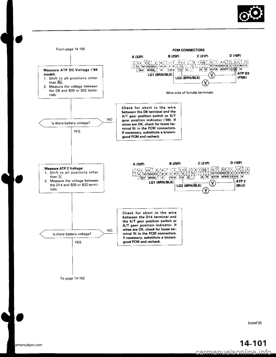
From page 14 100PCM CONNECTORS
B (2sP)c (31P}
' t d. , lll;;l';nl, :if
D t16P)
D {16P1
ATP D3{PNK)LGl (BRN/BLK}LG2IBRN/BLK)
Wire side of female terminals
B l25Plc (31P1
LGl IBRN/BLKI
A (32P1
Measure ATP D3 Vollage l'98model):1. Shift to all positions other
than E.2, Measure the voltage between
the D8 and 820 or 822 termi-
nals-
Check for shott in the wire
belween lh6 08 terminal and the
A/T gear posilion switch or A/Tgear position indicator ('98) lf
wires are OK, check lor loose ter-
minal tit in rhe PCM connectors.
ff necessary, substitute a known_good PCM and recheck.
ls there battery voltage?
Mearure ATP 2 voltage:1. Shift to all positions otherthan E.2. Measure the voltage betweenthe D14 and 820 or 822 termi
nals.
Check for short in the wire
between tho D1{ terminal and
the A/T gear posilion switch or
A/T gear position indicalor. lf
wiles are OK, check for loose t€r'
minal fit in the PCM connectors.It necessarv, substitute a known-good PCM and recheck.
To page 14-102
(cont'd)
14-101
www.emanualpro.com
Page 624 of 1395
Electrical Troubleshooting ('98 - 00 Models)
Troubleshooting Flowchart - Shift Control Solenoid Valve A (cont'd)
From page 14-106
Wire side of female terminals
Moasure VB SOL Voftago:1. Turn the ignition switch ONflr).2. Measure the voltage betweenthe D5 and 820 or 822 termi-nals,
Check lor blown No. 15 (7.5 Alfuse in the under-dash fuse/relaybox. lf the tuse is OK, repair openin the wi.e between the D5 ter-minal and the under-dash fuse/relay box.
ls there battery vohage?
Check for loose terminalfit in thePCM connectors. lf necessary,subltitute a known-good PCMand recheck.
VB SOL IBLK/YEL)
14-108
www.emanualpro.com
Page 639 of 1395
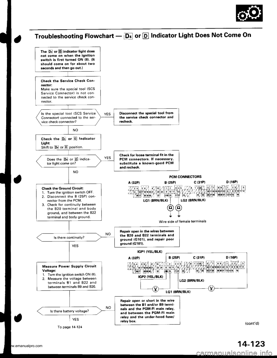
Troubleshooting Flowchart - Df or @ Indicator Light Does Not Come On
PCM CONNECTORS
B t2sPl c (31D (16P)
l*f4tr 8-
f - -- -6 3 rol ,: irr t lrpri$fe?0?r/a)1 e 'oI 13 11/ / l//|rrr I , ltelx ?r2? r,/i-T_LG1 {8RN/BI-KI I LG2 (BRN/BL()I
@@I++
Wire side of lemale terminals
(cont'd)
14-123
The E or El indicator light doe3not cofie on when the ignitaon
switch is first turned ON {ll). {ltshould como on for about two
s.cond3 and ihen go out.l
Check ths Service Check Con-
neclor:Make sure the special tool (SCS
Service Connector) is not connected to the service check connector.
Disconnecl the special lool lromtha service check connoctor andrecheck.
ls the special tool (SCS ServiceConnector) connected to the ser_vice check connector?
check the E or E Indicator
Ught:Shift to E or E position.
Check for loo3e t6lminal tit in thePCM connectors. lf necessary.substitute a known-good PCMand recheck.
Does the E or P indica-tor light come on?
Check the Gtound Circuil:1. Turn the ignition switch OFF.2. Disconnect the B (25P) con-nector from the PCM.3. Check for continuitY betweenthe 820 terminal and bodyground, and between the 822
terminal and body ground.
Repair open in the wires betweenthe 820 and 822 terminals andground {G1011, and r€Pair Poorground (G101).
ls there continuity?
Measure Power Supply CircuitVoltage:1. Turn the ignition switch ON 1ll).2. Measure the voltage betweenterminals B1 and 822 andbetween terminals Bg and 820.
Repair open or short in tho wi.ebetween the 81 and/or Bg tormi-nals and the PGM-FI main r€lay,.nd between tho PGM-FI mainrelay and the under-hood tuse/relay box.
ls there battery voltage?
A l32Plc (31P)
c (31P)
YES
To page 14-124
www.emanualpro.com
Page 642 of 1395
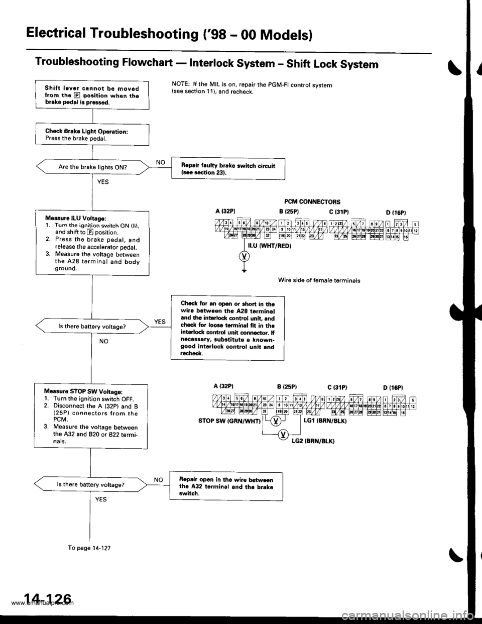
Electrical Troubleshooting ('98 - 00 Modelsl
Troubleshooting Flowchart - Interlock System - Shift Lock System
NOTE: li the MIL is on, ropair the PGM-FI controt system{see section 11), and recheck.
PCM CONNECTORS
c l3lPl
Wire side of female lerminals
c t3lPt
D {16P1
1 tttt/ 5t/ 1 a t /tlt 1 t\/t ,/ VVV tl t ttj,r\1e\10l211n . I 3 rholr1 t?m@-@Effilil"
D (lCPl
| 2ttt/ ;t /n) ).tt)/ 1 21:/ tvvvvv nnvl.lnl2
I r r ero
12wE gp]P] polr EI!l!!i r.
a (25P1
LGl {8RN/ALKI
Shift levor cannot be mov6dllom the E po3ition when th6blako pedal is pre3sed.
Ch€ck BJake Light Oporation:Press the brake pedal.
B6pair tlutty brrko 3whch circuitl..e rection 231.Are the brake lights ON?
Me.sure ILU Voltage:1. Turn the ignition switch ON (ll1,and shiftto E position.2. Press the brake pedal, andrelease the accelerator pedal.3. Measure the voltage betweenthe A28 terminal and bodygrouno.
Chock tor an open or short in thewi.o botwoen tha A28 t6rminrland thc intorlod( control unit, rndcheck tor loose torminrl fit in theintorlock conftol unh connoctor. lfnocassaryr aubstitute a known-good intollock control unit rndroch6d(
Mor3uro STOP SW vohsgo:1. Turn the ignition switch OFF.2. Disconnect the A (32P1 and B(25P) connectors {rom thePCM.3. Measure the voltage betweenthe A32 and 820 or 822 termi-nals,
Repair op6n in tho wir€ betwsenthe A32 t6.minal and th6 brake3witch.
ls there battery voltage?
fo page 14-121
14-126
www.emanualpro.com