Page 480 of 1395
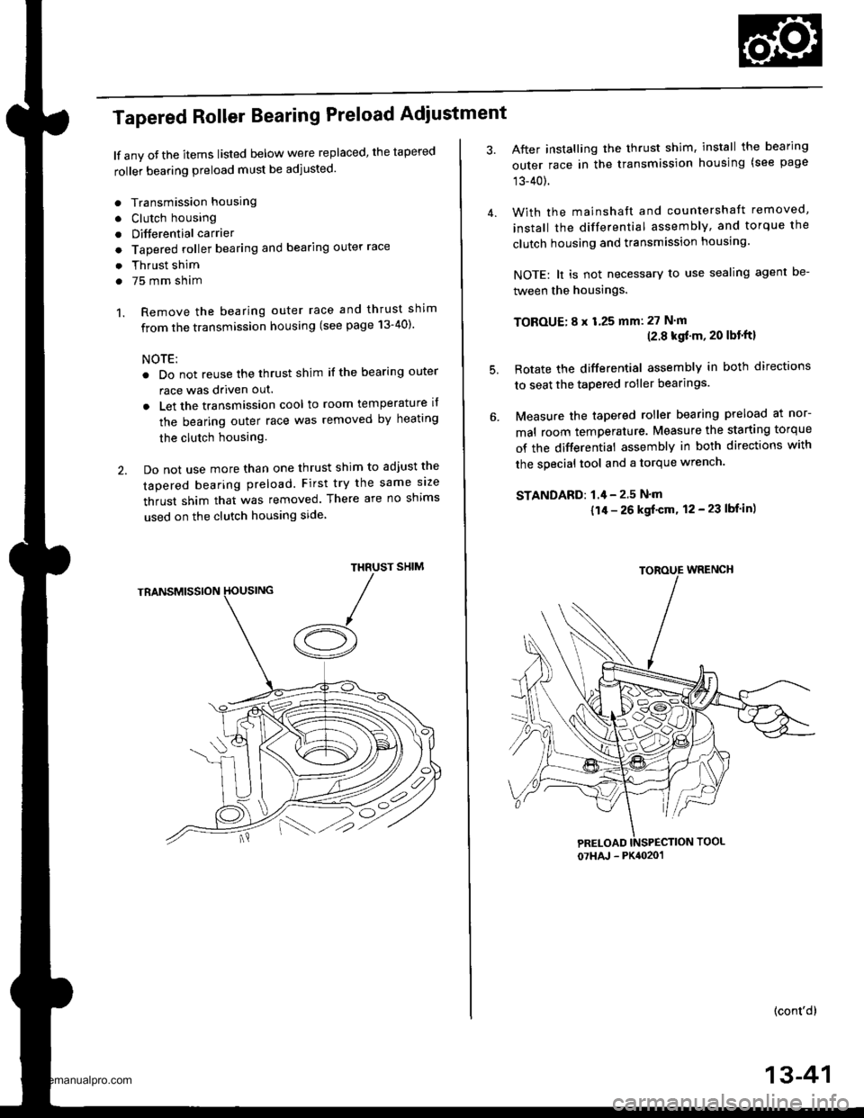
Tapered Roller Bearing Preload Adiustment
lf any oJ the items listed below were replaced, the tapered
roller bearing preload must be adjusted.
. Transmission housing
. Clutch housing
. Differential carrier
o Tapered roller bearing and bearing outer race
. Thrust shim
. 75 mm sham
1. Remove the bearing outer race and thrust shim
from the transmission housing (see page 13-40)'
NOTE:
. Do not reuse the thrust shim if the bearing outer
race was driven out.
. Let the transmission cool to room temperature il
the bearing outer race was removed by heating
the clutch housing.
2. Do not use more than one thrust shim to adjust the
tapered bearing preload. First try the same size
thrust shim that was removed. There are no shims
used on the clutch housing side
SHIMTHRUST
/A
After installing the thrust shim, install the bearing
outer race in the transmission housing (see page
13-40).
With the mainshaft and countershaft removed,
install the differential assembly, and torque the
clutch housing and transmission housing.
NOTE: lt is not necessary to use sealing agent be-
tween the housings.
TOBOUE; 8 x 1.25 mm: 27 N'm(2.8 kgf'm, 20 lbt'ftl
Rotate the differential assembly in both directions
to seat the tapered roller bearings.
Measure the tapered roller bearing preload at nor-
mal room temperature. Measure the starting torque
of the differential assembly in both directions with
the special tool and a torque wrench.
STANDAFD: 1.4 - 2.5 N'm
{1/r - 26 kgf'cm, 12 - 23 lbf in)
(cont'd)
4.
5.
07HAJ - PK4020'�1
13-41
www.emanualpro.com
Page 495 of 1395
Transfer Assembly
Reassembly (cont'dl
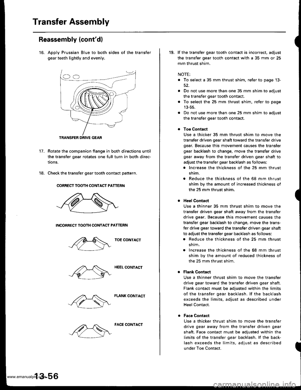
16. Apply Prussian Blue to both sides of the transfer
gear teeth lightly and evenly.
Rotate the companion flange in both directions until
the transfer gear rotates one full turn in both direc-
tions.
Check the transfer gear tooth contact pattern.
CORREST TOOTH CONTACT PATTERN
INCORRECT IOOTH CONTACT PATTERN
TOE CONTACT
HEEL CONTACT
FLANK CONTACT
17.
18.
TRANSFER DRIVE GEAR
13-56
FACE CONTACT
19. lf the transfer gear tooth contact is incorrect, adjust
the transfer gear tooth contact with a 35 mm or 25
mm thrust shim.
NOTE:
. To select a 35 mm thrust shim, refer to page '13-
. Do not use more than one 35 mm shim to adjust
the transfer gear tooth contact.
. To select the 25 mm thrust shim, refer to page
13-55.
a Do not use more than one 25 mm shim to adjust
the transfer gear tooth contact.
Toe Contact
Use a thicker 35 mm thrust shim to move the
transfer driven gear shaft toward the transfer drive
gear. Because this movement causes the transfer
gear backlash to change, move the transfer drive
gear away from the transfer driven gear shaft to
adjust the transfer gear backlash as iollows;
. Increase the thickness of the 25 mm thrust
shim.
. Reduce the thickness of the 68 mm thrust
shim bv the amount of increased thickness of
the 25 mm thrust shim.
Heol Contact
Use a thinner 35 mm thrust shim to move the
transfer driven gear shaft away from the transfer
drive gear. Because this movement causes the
transfer gear backlash to change, move the trans-
fer drive gear toward the transfer driven gear shaft
to adjust the transfer gear backlash as follows:
. Reduce the thickness of the 25 mm thrust
sh im.
a Increase the thickness of the 68 mm thrust
shim by the amount of reduced thickness of
the 25 mm thrust shim.
Flank Contact
Use a thinner thrust shim to move the transfer
drive gear toward the transfer driven gear shaft.
Flank contact must be adtusted within the limits
of the transfer gear backlash. lf the backlash
exceeds the limits, adjust as described under
Heel Contact.
Face Contsct
Use a thicker thrust shim to move the transfer
drive gear away from the transfer driven gear
shaft. Face contact must be adjusted within the
limits of the transjer gear backlash. lf the back-
lash exceeds the limits, adjust as described
under Toe Contact.
www.emanualpro.com
Page 507 of 1395
Transmission Assembly
Reassembly (cont'dl
6. Installthe reverse lock cam on the clutch housing.
6x1.0mm15 N.m (1.5 kgf.m, 11 lbf.ftl
REVERSE LOCK CAM
7. lnstall the oil seal.
HANDLE07749 - 001mO
ATTACHMENT,32x35mm07745 - 0010100
OIL SEALReplace.
Install the select lever, spring washer, and springs
on the select arm.
SELECT LEVER
SELECT BETURNSPRING
5TH/REVERSESELECT RETURN
SPRING PINReplace.
SELECT ARM
9. Installthe select arm and spring pin.
13-68
10. Apply liquid gasket (P/N 08718 - 0001 or 08718 -
0003) to the select spring bolt threads, then install
the select spring bolt.
SELECT SPRING BOLT
39 N.m la.o kgf'm,29lbtft)
'I 1.Install the oil guide M plate.78 mm shim, and oil
guner plate in the transmission housing.
NOTE: Select the 78 mm shim according to the
measurements made on page 13-64,
OIL GUIDE M PLATE
www.emanualpro.com
Page 514 of 1395
18.
19.
Refill the transmission fluid (see page 13-3)
Install the four upper transmission mounting bolts.
12 x 1.25 mm6it N.m 16.5 kgf m,il7 lbf.ftl
20. Connect the vehicle speed sensor (VSS) connector.
------------,-
VSS CONNECTOR
21, Install the cable bracket from the clutch housing.
8 x 1.25 mm27 N.m (2.8 kgt'm. 20 lbtftl
COTTER PINR€place.
STEELWASHER
COTTEN PINReplace.
STEELWASHER
PLASTICWASHER
22.
)a
SELECTCABLE
lnstall the shift cable and select cable to the levers,
then install plastic washers, steel washers, and cot-
ter prns,
Connect the back-up light switch connector. and
install the wire harness clamP.
6x1.0mm9.8 N.m {1.0 kgf.m,
HARNESS CLAMP
(cont'd)
13-75
www.emanualpro.com
Page 533 of 1395
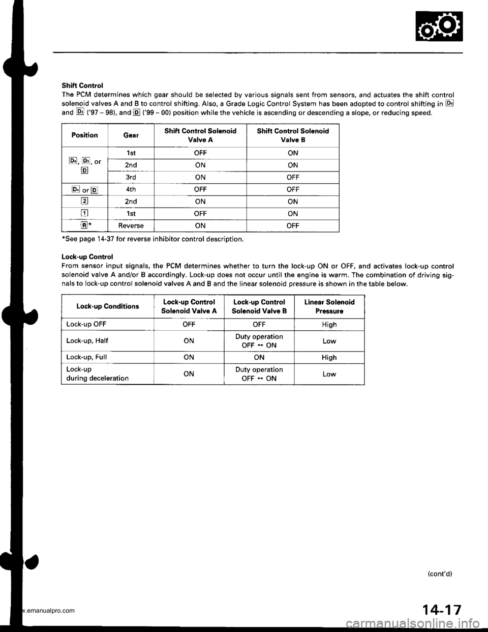
Shift Control
The PCM determines which gear should be selected by various signals sent from sensors, and actuates the shift control
solenoid valves A and B to control shifting. Also. a Grade Logic Control System has been adopted to control shifting in E
anO E ('gZ - gg), and E ('99 - 00) position while the vehicle is ascending or descending a slope, or reducing speeo.
PositionGearShift Control Solenoid
Valve A
Shift Control Solonoid
Valve B
E, E, Or
E
'I stOFFON
2ndONON
3rdONOFF
E orE4thOFFOFF
a2ndONON
tr1stOFFON
E-ReverseONOFF
*See page 14-37 for reverse inhibitor control description.
Lock-up Control
From sensor input signals, the PCM determines whether to turn the lock-up ON or OFF, and activates lock-up control
solenoid valve A and/or B accordingly. Lock-up does not occur until the engine is warm. The combination of driving sig-
nals to lock-up control solenoid valves A and B and the linear solenoid pressure is shown in the table below.
Lock-up ConditionsLock-up Control
Solonoid Valve A
Lock-up Control
Solenoid Valve B
Linear Solenoid
Pressuro
LOCK-Up \JrrOFFOFFHigh
Lock-up, HalfONDuty operation
OFF - ON
Lock-up, FullONONHish
Lock-up
during decelerationONDuty operation
OFF - ONLow
(cont'd)
14-17
www.emanualpro.com
Page 572 of 1395
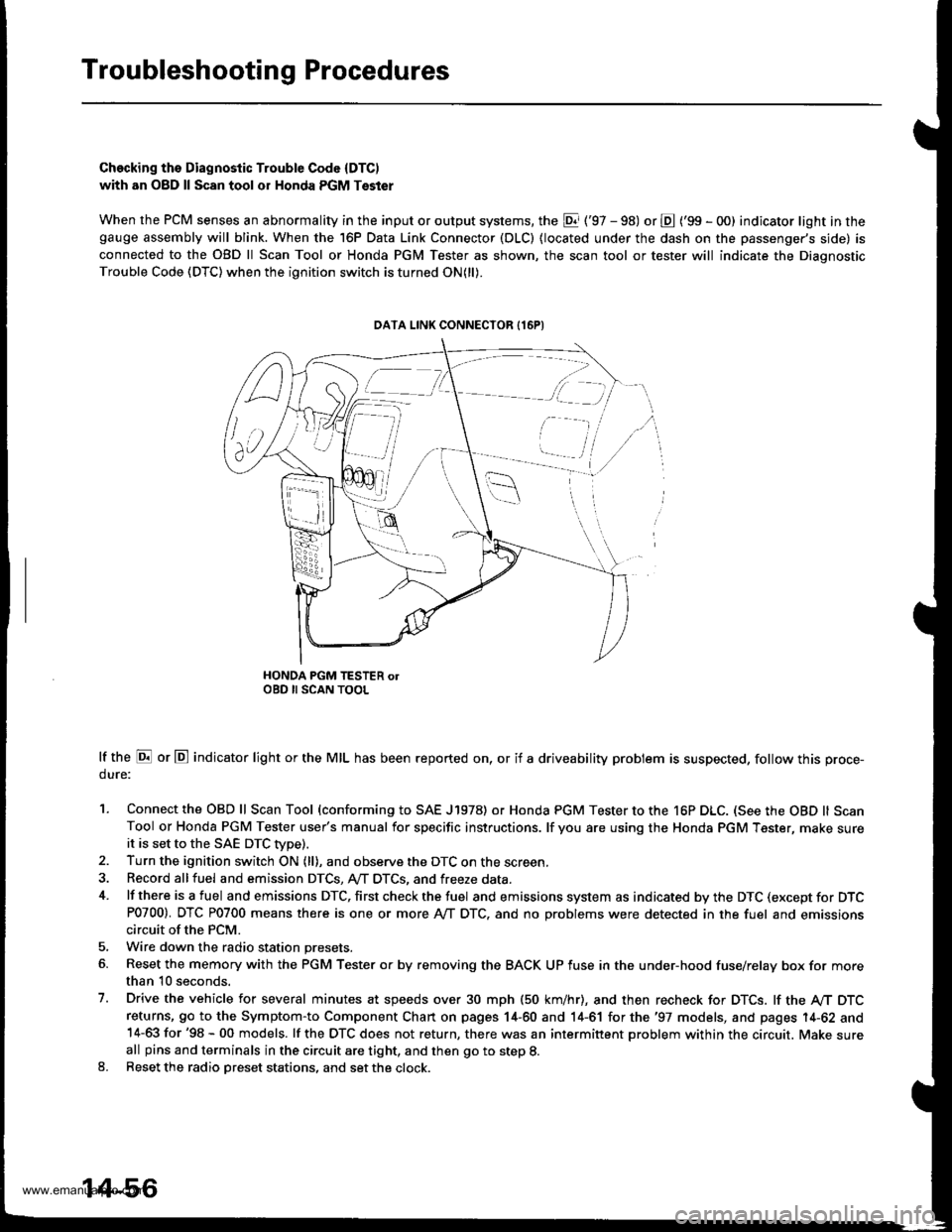
Troubleshooting Procedures
Checking ths Diagnostic Trouble Code (DTC)
with an O8D ll Scan tool or Honda PGM Tsster
When the PCM senses an abnormality in the input or output systems, the El ('97 - 98) or E ('99 - O0) indicator light in thegauge ass€mbly will blink. When the 16P Data Link Connector (DLC) {located under the dash on the passenger's side) is
connected to the OBD ll Scan Tool or Honda PGM Tester as shown, the scan tool or tester will indicate the Diagnostic
Trouble Code (DTC) when the ignition switch is turned ON(ll).
HONDA PGM TESTER olOBD II SCAN TOOL
lf the E or E indicator light or the MIL has been reported on, or if a driveability problem is suspected, follow this proce-
dure:
1. Connect the OBD ll Scan Tool (conforming to SAE J1978) or Honda PGM Tester to the 16P DLC. (See the OBD ll ScanTool or Honda PGM Tester user's manual for specific instructions. lf you are using the Honda PGM Tester, make sureit is set to the SAE DTC Wpe).2. Turn the ignition switch ON (ll), and observe the DTC on the screen
3. Record allfuel and emission DTCS, A,,/T DTCS, and freeze data.
4. lf there is a fuel and emissions DTC, first check the fuel and emissions system as indicated by the DTC (except for DTCP0700). DTC P0700 means there is one or more Ay'T DTC, and no Droblems were detected in the fuel and emissionscircuit of the PCM.
5. Wire down the radio station presets.
6. Reset the memory with the PGM Tester o. by removing the BACK UP fuse in the under-hood fuse/relay box for morethan 10 seconds.
7. Drive the vehicle for several minutes at speeds over 30 mph (50 km/hr), and then recheck for DTCS. lf the A/T DTCreturns, 9o to the Symptom-to Component Chart on pages 14-60 and 14-61 for the '97 models, and pages 14-62 and14-63 for '98 - 00 models. lf the OTC does not return, there was an intermittent problem within the circuit. Make sureall pins and terminals in the circuit are tight, and then go to step 8.8. Reset the radio Dreset stations, and set the clock.
DATA LINK CONNECTOR {16PI
[ -=.r,
ili,i /i,
v,., i
14-56
www.emanualpro.com
Page 573 of 1395
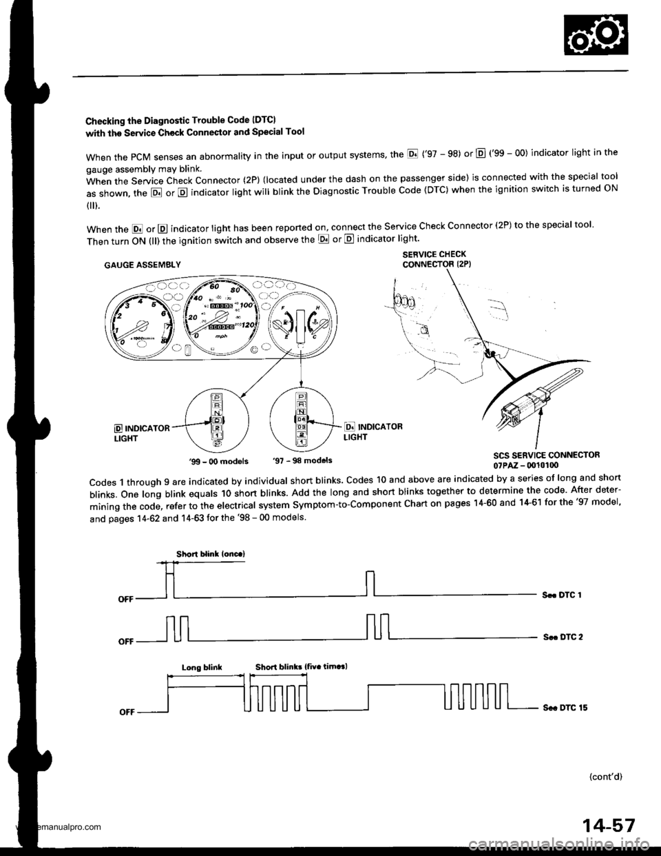
Checking the Diagnostic Trouble Code IDTCI
with the Servic€ Check Connestol and Special Tool
when the PcM senses an abnormality in the input or output systems' the E ('97 - 98) or E (gS - OO) indicator light in the
gauge assembly may blink.
When the Service Check Connector (2P) (located under the dash on the passenger side) is connected with the special tool
as shown, the E or E indicator light will blink the Diagnostic Trouble Code (DTC) when the ignition switch is turned ON
{ ).
when the E or E indicator light has been reponed on, connect the service check connector (2P) to the special tool
Then turn ON (ll) the ignition switch and observe the E or E indicator light'
.AUGE AssEMaLY $1,"^f:tT"'ff,
SCS SERVICE CONNECTOR07PAz - (x!l0100
codes 1 through 9 are indicated by individual short blinks. codes 1o and above are indicated by a series of long and short
blinks. one long blink equals 1o short blinks. Add the long and short blinks together to determine the code. After deter-
mining the code, refer to the electrical system symptom-to-component chart on pages 14-60 and 14-61 for the '97 model,
and pages 14-62 and 14-63 tor the '98 - 00 models.
Sr. DTC 1
S.. DTC 2
Long blinkShori blink! {fiv. timt l
Sc. DTC 15
(cont'd)
'99 - O0 models '97 - 98 models
Short blinl lonc.)
14-57
www.emanualpro.com
Page 576 of 1395
Symptom-to-Component Chart
Electrical System -'97 Model
DTC*: The DTc in parentheses is the code the loa indicator right indicates when the Data LinkConnector is connected to the Honda pGM Tester.
DTC*E Indicatol
LightMILDetection ltemPage
P 1753
(1)BlinksONLock up control solenoid valve A(see page 14-64)
P1758
\21
B linksONLock-up control solenoid valve B(see page 14-66)
P 1705
(5)BlinksONA,/T gear position switch (short to ground)(see page 14-68)
P1706
(6)OFFONA,/T gear position switch {open)(see page 14-70)
P0753
\11
B linksONShift control solenoid valve A(see page 14-72)
P0758
(8)BlinksONShift control solenoid valve B(see page 14-74)
P0720
(9)BlinksONCountershaft speed sensor{see page 14-76)
P0715
(15)B linksONMainshaft speed sensor(see page l4-78)
P17 68( 16)
BlinksONLinear solenoid(see page 14-80)
P0740
{40)
OFFONLock-up control system(see page 14-82)
P0730
(41)OFFONShift control system(see page 14-84)
14-60
www.emanualpro.com