Page 976 of 1395
Check fo. a short to power in thaPCOM, SCOM circuhi1. Start the engine.2. Measure the voltage betweenbody ground and ABS controlunit 26P connector terminalsNo. I and No.2 individually.
'Repair short to powor in thsFCOM circuit wiro botwoon th€ABS control unit and the under-hood ABS tuse/r.lay box.. Repeir 3hort to power in thoPCOM or SCOM circuit wirebetwegn tho ABS control uniiand ths modulator unh,. R.placo tha modulatoi unit.(Shon to power in.ido th6 unitl
ls there 8 V or more?
Tu.n tho ignhion switch OFF andconnect thc SCS 3orvice connec-tor. Then turn thc ignition switchON (lll and measure tha voltagobotween the PCOM .nd SCOMtsrminal3 and body gJound. Itther6 is 0 V, .epleco tho ABS con-trol unit.
ABS CONTROL UNIT 26P CONNECTOR
PCOM
Wire side of temale terminals
NOTE: 8 V or more indicates a short to
(GRN/WHTI SCOM
www.emanualpro.com
Page 977 of 1395
Troubleshooting
DTC 61: lgnition Voltage
- Whh the .ngine running. theABS indicator b ON,- With the SCS servicc connaetor connoctod {sao prgo 1998},DTC 61 b indi)atod.
Problom vorification:1. Erase the DTC.2. Start the engine.
Does the ABS indicator come onand is DTC 61 indicated?Tho ryrtom i. OK rt thb timo.
Ch.ck the lG2 circuit:Measure the voltage betweon theABS control unit 26P connectorterminal No.3 and body ground.
ls there 18 V or above?
lf the volt gc b 0 V, ch6d( to. anoD€n in lhe lG2 circuh.I thole ir 12 - 17 V, subatilui. !known-good ABS control unit .ndr€d|eck.
Wire side of temale termioals
www.emanualpro.com
Page 979 of 1395

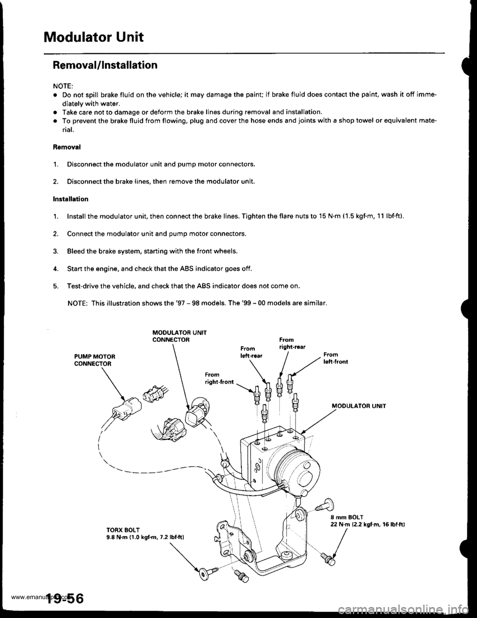
Modulator Unit
Removal/lnstallation
NOTE:
. Do not spill brake fluid on the vehicle; it may damage the painu if brake fluid does contact the paint, wash it off imme-
diately with water.
a Take care not to damage or deform the brake lines during removal and installation.
. To prevent the brakefluidfrom flowing, plug and coverthe hose ends and joints with a shop towel or equivalent mate-
rial,
Romoval
1. Disconnect the modulator unit and Dump motor connectors.
2. Disconnect the brake lines, then remove the modulator unit.
lnstallation
1. Install the modu lator u nit. then con nect the brake lines. Tighten the flare nuts to 15 N.m ( 1.5 kgf.m, 1 1 lbf.ft).
2. Connect the modulator unit and oumo motor connectors.
3. Bleed the brake system, staning with the front wheels.
4. Start the engine, and check that the ABS indicator goes off.
5. Test-drive the vehicle, and check that the ABS indicator does not come on,
NOTE: This illustration shows the '97 - 98 models. The'99 - 00 models are similar.
PUMP MOTORCONNECTOR
MODULATON UNIT\*\
,@
I
TORX EOLT9.8 N,m (1.0 kgf.m.7.2lbf ftl
19-56
www.emanualpro.com
Page 1065 of 1395
Moldings
Roof Molding Replacement
CAUTION:
. Put on glovgs to protect your hands.
. Wh€n prying with a {lat-tip screwdriver, wrap it whh protective tape to prevent damage
NOTE:
. Take care not to scratch the body.
. The steel core in the roof molding cannot be restored to it original shape once it is bend. Replace the roof molding when
the steel core is bent.
. Starting at the front, carefully pry off the roof molding.
>: Clip locationsA>,2
ROOF MOLDINGInstallation is the reverse of the removal procedure.
NOTE:
. Take care not to damage the windshield molding.
. Make sure the roof molding is installed securely.
STEEL CORE
B>,3
20-84
www.emanualpro.com
Page 1169 of 1395
DAYTIME BUNNING LIGHTSCONTROL UNIT (Canrda) {'98 - (X) modok)IGNITION KEY LIGHTCONTROL UNIT l€7 model)
OAYTIME RUNNING LIGHTSCONTROL UNIT lcanad!l l'97 modell
CRUISE CONTNOL UNIT
HORN BELAY 137 modellIwiro color3: WHT/GRN, IIWHT/GBN, GRY, and BLU/REDI
IWir6 color3: BLK/WHT, BLK^ UHT,I
lGRY,.nd BLx/nED I
STARTER CUT RELAY {'98 - 00 modelsl
STARTEn CUT RELAY l€7 mod€ll
lwire colors: BLK/WHT, BLK/WHY,l
IGRY, and BLK/RED IHORN FELAY l'98 - 00 modcb)lwire coloF: WHT/GRN, lLWHT/GRN, GRY, and BLU/REDI
{cont'd)
23-9
www.emanualpro.com
Page 1171 of 1395

Gonnector ldentification and Wire Harness Routing
How to ldentity Connectors:
ldentification numbers have been assigned to all connectors, The number is preceded by the letter "C" for connectors.
"G" for ground terminals or "T" for non-ground terminals.
Location
HarnessEngine CompartmsntDashboardOthers lFloor, Door,
8oof, Tailgate)
Starter cableT1, T2 and @
Battery ground cableG1 and O
Engine ground cableT3
Transmission ground cableT4
G3
Engine wire harnessC101 through C137
T101 and T102
G101
Engine compartment ware harnessC201 through C218
G201 and G202
Under-hood ABS fuse/relay box
wire harness
t5ano9
Main wire harnessC301 through C309
C351 through C361
C401 through C447
G401 and G402
Dashboard wire harnessC501 through C524 (C525)
G501
Left side wire harnessC551 through C581
G551, G552 and G553
Right side wire harnessC601 through C605
lnterior wire harnessC701 through C703
Rear bumper wire harnessC641 through C643
Heater sub-harnessC731 through C740
Secondary heated oxygen sensor
sub-harness
C721 through C722
Combination switch sub-harnessC751 through C760
Driver's door wire harnessC661 through C667
Front passenger's door wire harnessC6Tl through C676
Left rear door wire harnessC681 through C684
Right rear door wire harnessC69'l through C694
Rear wire harnessC611 through C520
Tailgate wire harnessC631 through C634
G631
SRS main harnessC801 through C808
G801
High mount brake light sub-harnessC651 through C653
Fuel tank oressure sensor sub-harnessC645 through C647
www.emanualpro.com
Page 1172 of 1395

Connector ldentification and Wire Harness Routing
Connoctor or
Terminal
Number of
CavitiesLocationConnects toNotes
T1
r2
Right side of engine compartment
Right side of engine compartment
Under-hood fuse/relay box
Starter motor
oBatteryBattery positive terminal
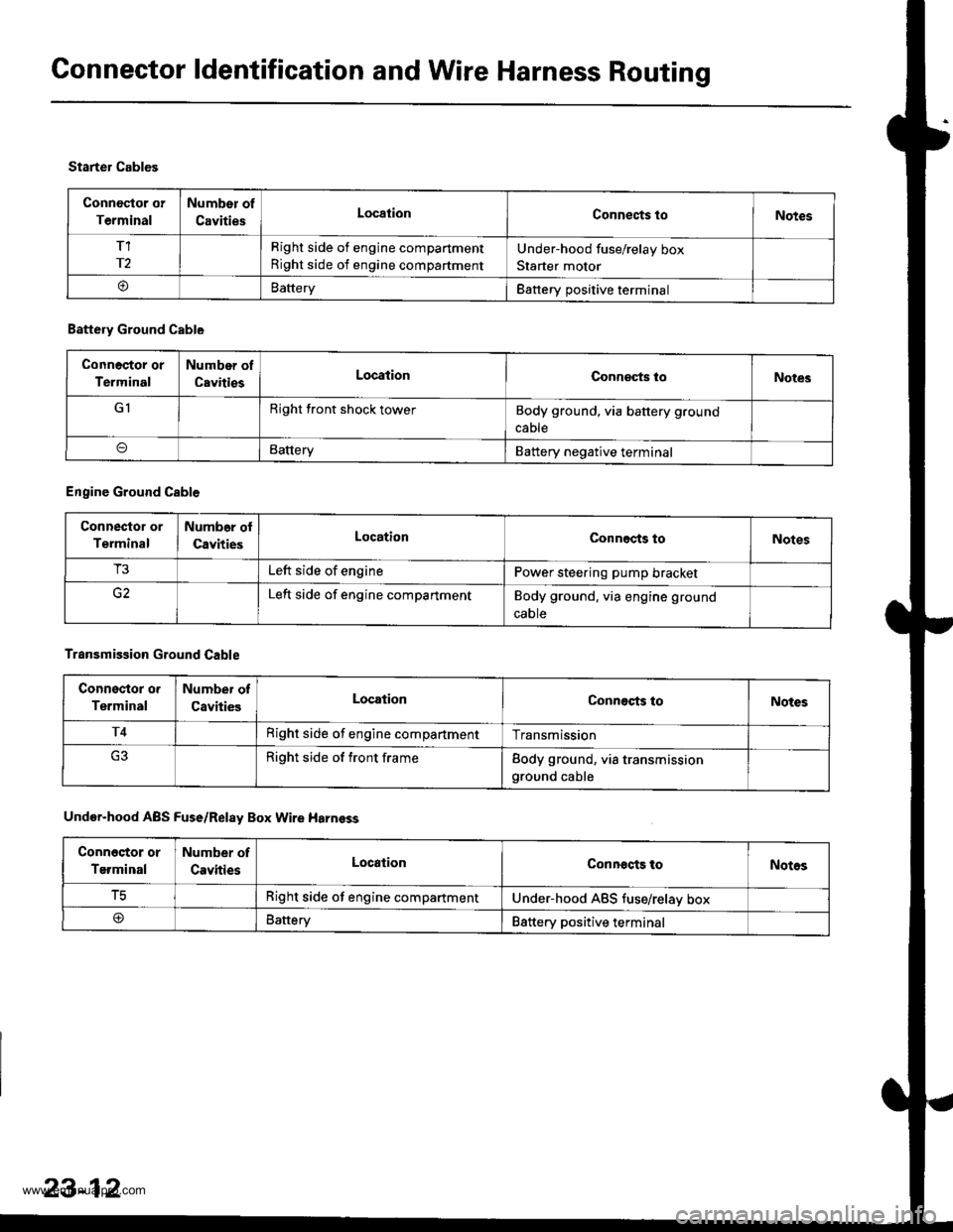
Starter Cables
Battery Ground Cable
Connoctor or
Terminal
Number of
CavitiesLocationConneqts loNotes
GIRight front shock towerBody ground, via battery ground
cable
BatteryBattery negative terminal
Engine Ground Cable
Connector or
Terminal
Numb6r ol
CavitiesLocationConnects toNotes
T3Left side of enginePower steering pump bracket
Left side of engine compartmentBody ground. via engine ground
caote
Transmission Ground Cable
Connsstor o.
Terminal
Number of
CavitiesLocationConnects toNotes
T4Right side of engine compartmentTransmission
Right side of front frameBody ground, via transmissionground cable
Under-hood ABS Fuse/Relay Box Wire Harnsss
Conn6stor or
Terminal
Number of
CavitiesLocationConnocts toNotos
tcRight side of engine compartmentUnder-hood ABS tuse/relav box
@Battery88ttery positive terminal
23-12
www.emanualpro.com
Page 1173 of 1395
STARTER CABLE
UNDER-HOOD ABS FUSE/RELAYBOX WIRE HARNESS
@
EATTERY GROUNDCABLE
ENGINE GROUNDCABLE
TRANSMISSION GROUNDCABLE
23-13
www.emanualpro.com