2000 HONDA CR-V wheel torque
[x] Cancel search: wheel torquePage 525 of 1395
2.
L
E Position
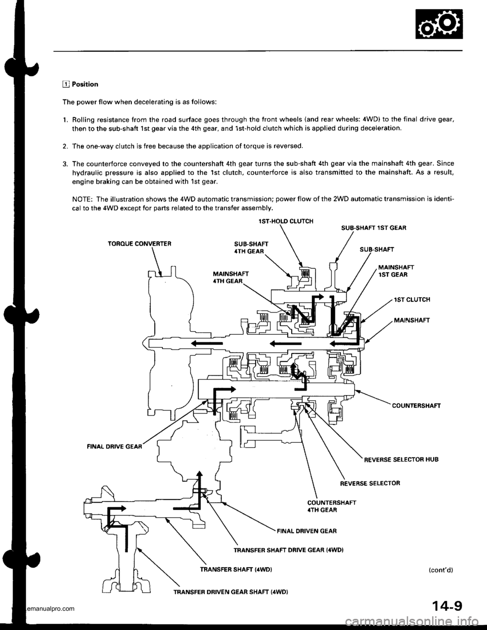
The power flow when decelerating is as follows:
Rolling resistance trom the road surface goes through the tront wheels (and rear wheels: 4WD) to the final drive gear.
then to the sub-shaft lst gear via the 4th gear. and 1st-hold clutch which is applied during deceleration.
The one-way clutch is free because the application of torque is reversed.
The counterforce conveyed to the countershaft 4th gear turns the sub-shaft 4th gear via the mainshaft 4th gear. Since
hydraulic pressure is also applied to the 1st clutch. counterforce is also transmitted to the mainshaft. As a result,
engine braking can be obtained with'lst gear.
NOTE: The illustration shows the 4WD automatic transmission; power flow of the 2WD automatic transmission is identi-
cal to the 4WD except tor parts related to the transfer assembly.
J.
SUB.SHAFT 1ST GEAR
TOROUE CONVERTER
FINAL DRIVE GEAR
SUB.SHAFT{TH GEAR
MAINSHAFTlST GEAR
lST CLUTCH
MAINSHAFT
COUNTERSHAFT
REVERSE SELECTOR HUB
REVERSE SELECTOR
COUNTERSHAFTIITH GEAR
FINAL ORIVEN GEAR
TRANSFER SHAFT DRIVE GEAR {4WDI
TRANSFEB SHAFT {{WD){cont'd}
lST.HOLD CLUTCH
TRANSFER DRIVEN GEAR SHAFT {,lWDl
14-9
www.emanualpro.com
Page 671 of 1395
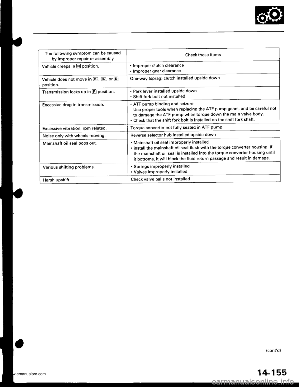
The following symptom can be caused
by improper repair or assemblYCheck these items
. lmproper clutch clearance
. lmproper gear clearance
One-way (sprag) clutch installed upside down
Park lever installed upside down
Shift fork bolt not installed
Vehicle creeps in N position.
Vehicle does not move in E, [D.lj, or E
position.
Transmission locks up in E position.
Excessive drag in transmission.ATF pump binding and seizure
Use proper tools when replacing the ATF pump gears, and be careful
to damage the ATF pump when torque down the main valve body.
Check that the shift fork bolt is installed on the shift fork shaft
not
Excessive vibration, rpm related.Torque converter not fully seated in ATF pump
Reverse selector hub installed upside downNoise only with wheels moving.
Mainshaft oil seal po9s out.Mainshaft oil seal improperly installed
lnstallthe mainshaft oil seal tlush with the torque converter housing lf
the mainshaft oil seal is installed into the torque converter housing until
it bottoms. it will block the fluid return passage and result in damage
Various shifting problems.. Springs improperly installed
. Valves improperly installed
Harsh upshift.Check valve balls not installed
(cont'd)
4-155
www.emanualpro.com
Page 672 of 1395

Symptom-to-Com ponent Chart
Hydraulic System (cont'd)
NOTES
See flushing procedure, page l4-264 and 265,
BSet idle rpm in gear to specified idle speed. lf still no good, adjust motor mounts as outlined in enginesection of this manual.
clf the large clutch piston O-ring is broken, inspect the piston groove for rough machining.
Dlf the clutch pack is seized or is excessively worn. inspect the other clutches fot wear, and check the orificecontrol valves, CPC valve, and linear solenoid for free movement.
lf the linear solenoid is stuck, inspect the clutches for wear.
lf the 1-2 shift valve is stuck closed. the transmission will not upshift. lf stuck open, the transmission hasno lst gear.
Hlf the 2nd orifice control valve is stuck, inspect the 2nd and 3rd clutch Dacks for wear.
lf the 3-4 orifice control valve is stuck, inspect the 3rd and 4th clutch packs for wear.
Jlf the clutch pressure control valve is stuck closed. the transmission will not shift out of lst gear.
Klmproper alignment of main valve body and torque converter housing may cause ATF pump seizure. Thesymptoms are mostly an rpm-related ticking noise or a high-pitched squeak.
Llf the ATF strainer is clogged with particles of steel or aluminum, inspect the ATF pump and differentialpinion shaft. lf both are OK and no cause for the contamination is found, replace the torque converter.
Mlf the lst clutch feed pipe guide in the end cover is scored by the mainshaft. inspect the ball bearing forexcessive movement in the transmission housing. lf oK, replace the end cover as it is dented. The o-rinounder the guide is probably worn.
N' Replace the mainshaft if the bushing for the 4th feed pipe is loose or damaged, lf the 4th feed pipe is darrFaged or out of round. replace the end cover.' Replace the mainshaft if the bushing for the l st feed pipe is loose or damaged. lf the 1st feed pipe is dam-aged or out of round, replace it.
oA worn or damaged sprag clutch is mostly a result of shifting the transmission in E!. E, or E positionwhile the wheels rotate in reverse. such as rocking the vehicle in snow.
PInspect the frame for collision damage.
lnspect for damage and wear:
l. Reverse selector gear teeth chamfers.
2. Engagement teeth chamfers of countershaft 4th and reverse gear.
3. Shift fork for scuff marks in center.
4. Differential pinion shaft for wear under pinion gears.
5. Bottom of 3rd clutch for swirl marks.
Replace items 1, 2, 3. and 4 if worn or damaged. lf transmission makes a clicking, grinding, or whirring noise,also replace mainshaft 4th gear, reverse idler gear, and countershaft 4th gear in addition to 1,2, 3, or 4.lf differential pinion shaft is worn, overhaul differential assembly, replace ATF strainer, and thoroughly cjeantransmission, flush torque converter. cooler, and lines,lf bottom of 3rd clutch is swirled and transmission makes gear noise. replace the countershaft and final drivenoear,
Be very careful not to damage the torque converter housing when replacing the main ball bearing. you
may also damage the ATF pump when you torque down the main valve body. This will result in ATF pumpseizure if not detected. Use the Drooer tools.
SInstall the main seal flush with the torque converter housing. lf you push it into the torque converterhousing until it bottoms out, it will block the fluid return passage and result in damage.
www.emanualpro.com
Page 675 of 1395
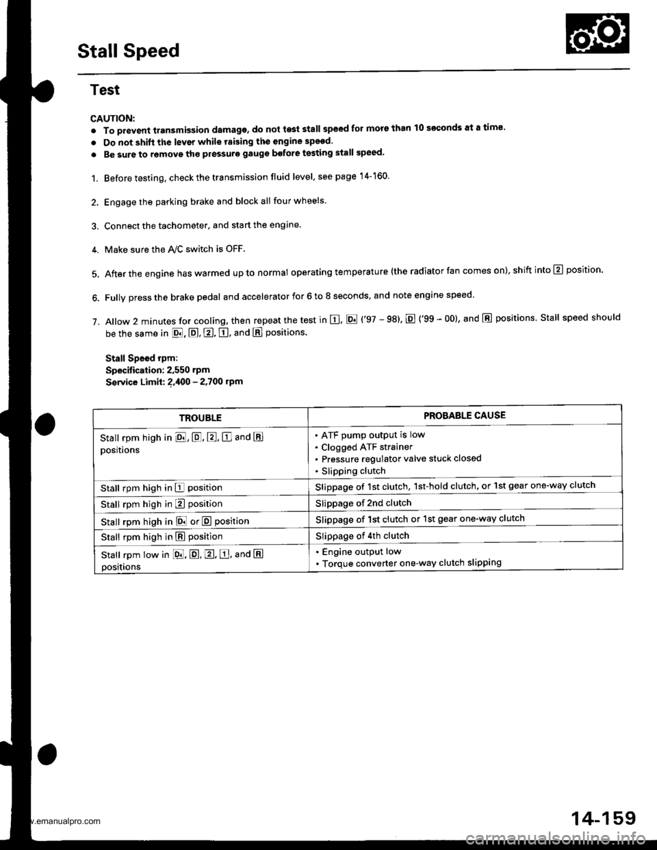
Stall Speed
Test
CAUTION:
. To prevent transmission damage, do not te3t stall speed for mors than 10 s€€onds at a time'
. Do not shift the lever while raising th€ engine spsed.
. Be sure to remove tho pressuro gauge bofore testing stall speed,
1. Before testing, check the transmission fluid level, s€e page 14-160.
2. Engage the parking brake and block all four wheels
3. Connect the tachometer, and start the engane.
4. Make sure the Ay'C switch is OFF
5. After the engine haswarmed upto normal operating temperature (the radiator fan comes on),shiftinto@ position.
6. Fully press the brake pedal and accelerator for 6 to 8 seconds, and note engine speed '
j. A|ow 2 minutes for cooling, then repeat the test in E, E ('97 - 98). E {'99 - 00}, and E positions. Stall speed should
be the same in E, E, E, tr. and E positions
Stall Speed rpm:
Specitication: 2,550 rpm
S€rvice Limit: ?,400 - 2.700 rpm
TROUBLEPROBAELE CAUSE
Stall rpm high in El, E, E, E and E
positions
ATF pump output is low
Clogged ATF strainer
Pressure regulator valve stuck closed
Slipping clutch
Stall rpm high in E positionSlippage of 1st clutch, 1st-hold clutch, or 1st gear one-way clutch
Stall rpm high in E positionSlippage of 2nd clutch
stall rpm high in E! or E positionSlippage of 1st clutch or 1st gear one-way clutch
Stall rpm high in E positionSlippage of 4th clutch
Stall rpm low in [dd, E. E, E, ana E
positions
. Engine output low
. Torque converter one-way clutch slipping
14-159
www.emanualpro.com
Page 680 of 1395

Transfer
4.
Inspection
@E Mako suro lifts, jacks, and safety standsare placod properly lsoe section t).
1. Raise the front of the vehicle, and make sure it issupported securely.
2. Set the parking brake, and block both rear wheelssecurely.
Shift to E position.
Make a reference mark across the propeller shaftand the transfer assembly flanges.
Separate the propeller shaft from the transferassembly.
8 x 1.25 mm32 N.m 13.3 kgl,m,24 lbf.ftlReplace.
14-164
\
6. Set a dial indicator on the transfer assembly flange.then measure the transfer gear backlash.
STANDARD: 0.06 - 0.16 mm (0.002 - 0.006 inl
7. lf the measurement is out of standard, remove thetransfer assembly and adjust transfer gear backlash{see page '14-232 thru 14-2491.
8. Check for fluid leaks between the mating faces oftransfer cover A and cover B.
9. lf there is a fluid leak, remove the cover, and reDlacethe O-ring.
'10. Check for fluid leaks between the mating face of thetransfer assembly and transmission.
11. lf there is a fluid l€ak, remove the transf€r assem-bly, and replace the O-ring,
12. Check the transfer oil seal for damage and fluidle8ks.
13, lf oil seal replacement is required. remove the trans-fer assembly, replace the oil seal, and adjust thetotal starting torque (see page 1+232 thtu ]'4-249||.
NOTE: Do not replace the oil seal with the transferassembly on the transmission.
COMPANION FLANGE
www.emanualpro.com
Page 794 of 1395

Description
Rear Differential
Outline
The Real-time 4WD-Dual Pump System model has a hydraulic clutch and a differential mechanism in the rear differential
assembly. Under normal conditions, the vehicle is driven by the front wheels. However, depending on to the driving force
of the front wheels and the road conditions. the system instantly transmits appropriate driving force to the rear wheels
without requiring the driver to switch between 2WD (tront wheel drive) and 4WD (four wheel drive). The switching mecha-
nism between 2WD and 4WD is integrated into the rear differential assembly to make the system light and compact.
ln addition, the dual-pump system switches off the rear-wheel-drive force when braking in a forward gear. This allows the
braking system to work properly on models equipped with an Anti-lock Braking System (ABS).
Construction
The rear differential assembly consists of the torque control differential case assembly and the rear differential carrier
assembly. The torque control differential case assembly consists of the differential clutch assembly, the companion
flange, and the oil pump body assembly. The rear differential carrier assembly consists of the differential mechanism. The
differential drive and driven gears are hypoid gears.
The oil pump body assembly consists of the front oil pump, the rear oil pump, the hydraulic control mechanism, and the
clutch piston. The clutch piston has a disc spring that constantly provides the differential clutch assembly with a preset
torque to Drevent abnormal sound.
The clutch guide in the differential clutch assembly is connected to the propeller shaft via the companion flange, and it
receives the driving force lrom the transfer assembly. The clutch guide rotates the clutch plate and the front oil pump in
the oil pump body.
The clutch hub in the differential clutch assembly has a clutch disc that is splined with the hypoid drive pinion gear. The
hypoid drive gear drives the rear oil pump.
The front and rear oil pumps are trochoidal pumps. The rear oil pump capacity is 2.5 percent larger that the front oil pump
to handle the rotation difference between the front and rear wheels caused by worn front tires and tight corner braking.
The oil pumps are designed so the fluid intake works as a fluid discharge when the oil pumps rotate in reverse. Genuine
Honda CVT fluid is used instead of differential fluid.
Operation
When there is a difference in rotation speed between the front wheels (clutch guide) and rear wheels (hypoid driven gear),
hydraulic pressure from the front and rear oil pumps engages the differential clutch, and drive force from the transler
assembly is applied to the rear wheels.
The hydraulic pressure control mechanism in the oil pump body selects 4WD mode when the vehicle is started abruptly,
or when accelerating in a forward or reverse gear (causing rotation difference between the front and rear wheels). or
when braking in reverse gear {when decelerating). lt switches to 2WD mode when the vehicle is driven at a constant speed
in forwar! or reverse gear (when there is no rotation difference between the front and rear wheels), or when braking in a
fo rwa rd gear (when decelerating).
To protect the system, the differential clutch assembly is lubricated by hydraulic pressure generated by the oil pumps in
both 4WD and 2WD modes. Also, the thermal switch relieves the hydraulic pressure on the clutch piston and cancels 4WD
mode if the temDerature of the differential fluid rises above normal.
www.emanualpro.com
Page 800 of 1395
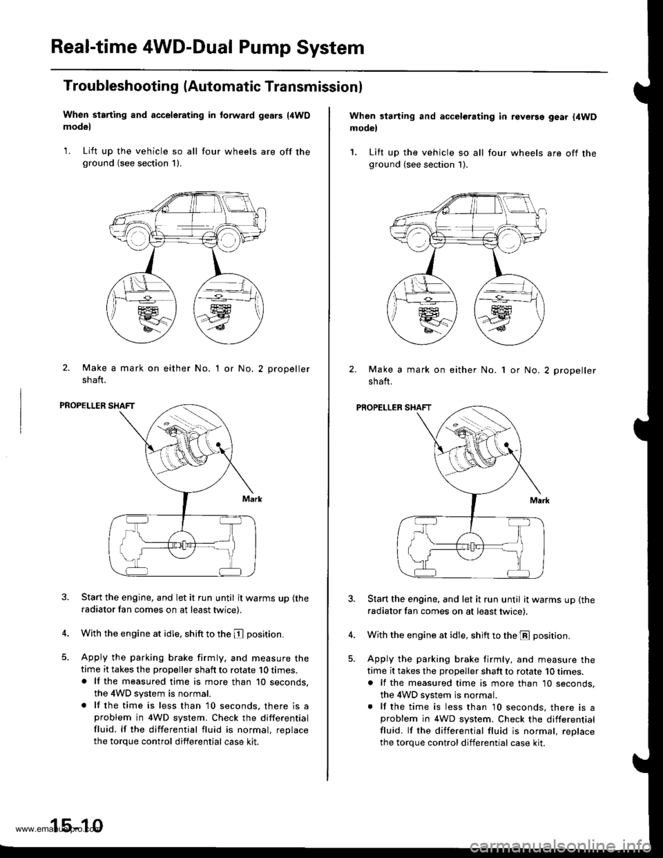
Real-time 4WD-Dual Pump System
Troubleshooting (Automatic Transmissionl
When starting and accelerating in forward gesrs {4WDmodel
1. Lift up the vehicle so all four wheels are off theground (see section 1).
2. Make a mark on either No.
shaft.
'I or No.2 propeller
PROPELLER SHAFT
Start the engine, and let it run until it warms up (the
radiator fan comes on at least twice).
With the engine at idle. shift to the E position.
Apply the parking brake firmly. and measure thetime it takes the propeller shaft to rotate 10 times.. lf the measured time is more than 10 seconds,
the 4WD system is normal.
. lf the time is less than 10 seconds, there is aproblem in 4WD system. Check the differential
fluid. lf the differential fluid is normal, replace
the torque control differential case kit.
15-10
When starting and accelerating in revGrsg gear {4WDmodel
1. Lift up the vehicle so all four wheels are off theground (see section 1).
Make a mark on either No.
shaft.
1 or No. 2 propeller
PROPELLER SHAFT
Start the engine. and let it run until it warms up (the
radiator fan comes on at least twicei.
With the engine at idle, shift to the E position.
Apply the parking brake firmly, and measure the
time it takes the proDeller shaft to rotate 10 times,. lf the measured time is more than 10 seconds,
the 4WD system js normal.. lf the time is less than 10 seconds, there is aproblem in 4WD system. Check the differential
fluid. lf the differential fluid is normal, reolace
the torque control differential case kit.
www.emanualpro.com
Page 801 of 1395
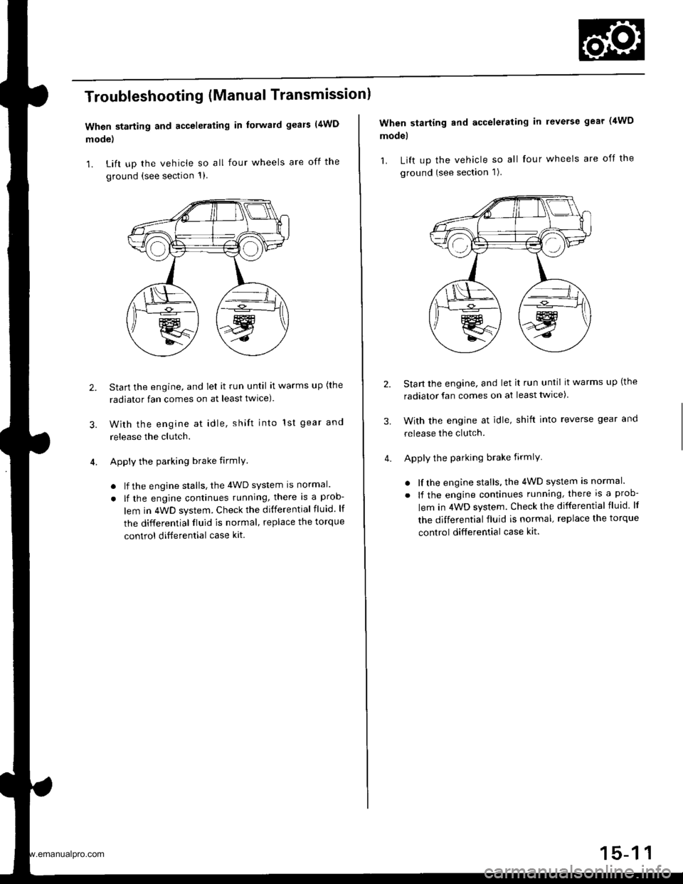
Troubleshooting (Manual Transmissionl
When starting and accelerating in forward gears (4WD
mode)
1. Lift up the vehicle so all four wheels are off the
ground {see section 1)
3.
Start the engine, and let it run until it warms up (the
radiator fan comes on at least twlce).
With the engine at idle, shift into 1st gear and
release the clutch.
Apply the parking brake firmlY
. lf the engine stalls, the 4WD system is normal.
. lf the engine continues running, there is a prob-
lem in 4WD system. Check the differential fluid. lf
the differential fluid is normal, replace the torque
control ditferential case kit.
2.
When starting and accelerating in reverse gear (4WD
model
1. Lift up the vehicle so all four wheels are off the
ground (see section 1).
Start the engine, and let it run until it warms up (the
radiator fan comes on at least twice)
With the engine at idle, shift into reverse gear and
release the clutch.
Apply the parking brake firmlY
. lf the engine stalls, the 4WD system is normal.
. lf the engine continues running, there is a prob-
lem in 4WD system. Check the differential fluid lf
the differential fluid is normal, replace the torque
control differential case kit.
3.
www.emanualpro.com