2000 HONDA CR-V Turn signal relay
[x] Cancel search: Turn signal relayPage 959 of 1395

Troubleshooting Precautions
ABS lndicalor
1 lf the system is oK, the ABS indicator goes off two seconds after turning the ignition switch oN 1l) wathout staningthe engine, and then comes on again and goes off after two seconds. This occurs because the ABS control unit isturned on by the lG2 power source.2. The ABS indicator comes on when the ABS control unit detects a problem in the system. However, even thouoh thesystem is operating properly, the ABs indicator will come on too, under the following conditions:. Signal disturbance
. Wheel spin
. Only drive wheels rotate. Battery voltage fluctuates
To determine the actual cause of the problem, question the customer about the problem, taking these conditions intoconsideration:
3 When a problem is detected and the ABS indicator comes on, the indicator can stay on until the ignition switch isturned OFF, or it can automatically go off, depending on the mode.. Indicator stays on untilthe ignition switch is turned off: When the system is in the system down mode.. Indicator automatically goes off: When the system is in the control inhibition mode.4 The ABS indicator stays on when the system is reactivated without erasing the DTC, but it goes off after starting thevehicle.
When the wheel sensor system is faulty and the ABS indicator comes on. the algorithm of the system automatically turnsoff the ABS indicator after the wheel speed signal returns to the normal speed. Also, when the DTc is erased, the cpu isreset and the ABS indicator goes off when the system checked out normal by the initial diagnosis.Therefore, test-drive the vehicle after servicing the wheel sensor system. and be sure that the ABS indicator does notcome on.
5 When the ABS control unit outputs battery voltage to the gauge assembly, the ABS indicator ooes off.
Diagnostic Trouble Code (DTCI
1. The diagnostic trouble code (DTc) is memorized when a problem is detected and the ABS indicator does not go off,or when the ABS indicator comes on.The DTc is not memorized when the ABS indicator comes on unress the cpu is activated,2 The memory can hold any number of DTCs. However, when the same DTc is detected twice or more, the tater one iswritten over the old one.
Therefore, when the same problem is detected repeatedly, it is recorded as one DTC.3. The DTCs are indicated in the order of ascending number, not in the order they occur.4. The DTCS are memorized in the EEPROM (non-volatile memorv).Therefore, the memorized DTcs cannot be canceled by disconnecting the battery. perform the specified procedures toerase the DTCS.
Self-diagnosis
1. Self-diagnosis can be classified into these four categories:' Initial diagnosis: Performed right after the eng ine starts and untir theABS indicator goes off.. Except ABS control: Performed when the ABS is not functioning.. During ABS control: Performed when the ABS is functioning.. During warning: Performed when the ABS indicator is ON.2. The system performs the fo|owing contrors when a probrem is detected by the serf-diagnosis:. ABS indicator ON. Memorv of DTC. Mode changetothe "system down mode,, or the ,,control inhibition mode,,.
MODEABS INDICATORMAIN
RELAY
SOLENOID
VALVECPURestart conditionDTC
SYSTEM
DOWNONNo
operation
Drive
inhibitionOperation*rlgnition
switchoFF - ON l)Memory
CONTROL
INHIBITIONONNo
operal|on
Drive
inhibitionOperationAutomaticlMemory
*1: Except CPU failure
19-36
www.emanualpro.com
Page 1106 of 1395

Troubleshooting
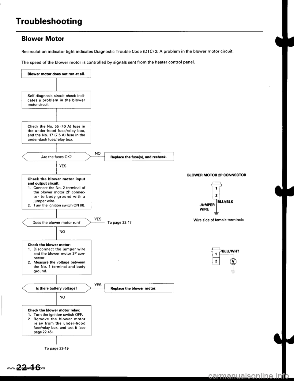
Blower Motor
Recirculation indicator light indicates Diagnostic Trouble Code (DTC) 2: A problem in the blower motor circuit.
The speed of the blower motor is controlled by signals sent from the heater control panel,
BLOWER MOTOR 2P CONNECTOR
JUMPEFw|RE
Wire side of lemale terminals
Blower motor do.3 not run at all.
Selt-diagnosis circuit check indi-cates a problem in the blowermotor circuit,
check rhe No. 55 (40 A) {use inthe under-hood fuse/relay box,and the No. 17 (7.5 A) fuse in theunder-dash fuse/relay box.
Replace th6 fuse(s), and rechalck.
Check tho blowe. motor inputand output cilcuh:1. Connect the No. 2 terminal ofthe blower motor 2P connec-tor to body ground with ajumper wrre.2. Turn the ignition switch ON (ll).
Does the blower motor run?
Chock the blower moto.:1. Disconnect the jumper wireand the blower motor 2P con-nector.2. Measure the voltage betweenthe No. l terminal and bodygrou nd.
Check tho blower motor rolay:1. Turn the ignition switch OFF.2. Romove the blower motorrelay from the under-hoodfuse/relay box, and test it (seepage 22 45l'.
fo page 22-11
fo page 22-19
22-16
www.emanualpro.com
Page 1168 of 1395

Relay and Gontrol Unit Locations
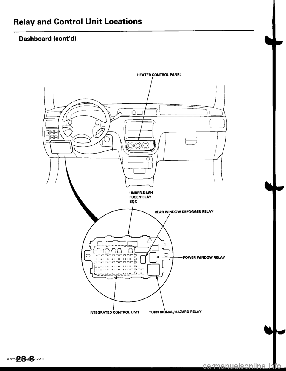
Dashboard (cont'd)
HEATER CONTROL PANEL
REAR WINDOW DEFOGGER RELAY
WINDOW RELAY
-rj,r1 /-\,r1Iu lJ-JlJ r*t
23-8
INTEGRATEO CONTROL UNITTURN SIGNAL/HAZARD RELAY
www.emanualpro.com
Page 1203 of 1395

Power Distribution
Fuse-to-Gomponent(sl Index (numerical sequence)
Under-hood Fuse/Rolay Box:
41
43
44
46
47
48
49
50
52
Capacity
'100 A
40A
7.5 A
15 A
40A
7.5 A
30A
204
204
15 A
10A
40A
40A
204
20A
Capacity
40A
204
7.5 A
wiro ColorFuseCircuit(s) Prot€cted
A
lgnition switch (BAT)
lntegrated control unit
Ceiling lights
Spotlights
PGM-Fl main relay
Not used
No. 7, 8, 10, 11 fuse in the under-dash fuse/relay box
Audio unit
Clock {'98 - 00 models)
Data link connector ('98 - 00 models)
ECM (VBU) {'98 - 00 models: M/T)
Heater control panel
PCM (VBU) (A./T)
Combination light switch (via under-dash fuse/relay box)
No. 20, 33 fuse in the under-dash fuss/relay box
Not used
Rear window defogger (via relay)
Door lock control unit
Hatch glass opener solenoid
Keyless door lock control unit ('98 - 00 models)
Horn relay
Horns (via relay)
via brake switch:
ABS control unit
Brake lights
Cruise control unit
ECM ('98 - 00 models: M/T)
High mount brake iight
PCM (4./T)
Trailer lighting connector
Turn signal/hazard relay (via switch)
Option connector (+B)
No. 6 fuse in the under-dash fuse/relay box
Blower motor (via relay)
Condenser fan motor (via relay)
Ay'C compressor clutch (via relay)
Radiator fan motor (via relay)
Wire Color Circuitls) Protoct
53
54
50
WHT/BLK
WHT/RED
WHT/BLK
WHT/BLU
WHT/BLU
WHT
WHT/GRN
WHT/GRN
WHT/GRN
WHT/BLK
WHT/RED
BLU/WHT
WHT
RED
BLK/RED
Under-hood ABS Fuss/nehy Box:
Fusg
61WHT
WHT/GRN
BRN/YEL
ABS pump motor {via relay}
ABS control unit
ABS control unit
{cont'd)
23-43
www.emanualpro.com
Page 1204 of 1395

Power Distribution
Fuse
1
3
5
6
7
I
9
10
11
12
13
14
"^
RED/B LU
RED/GRN
WHT/BLK
RED/VVHT
YEUBLK
RED
GRN/BLK
BLU/BLK
YEVBLK
YEUGRN
RED
BLK/YE L
BLK/VVHT
17
7.5 A
7.5 A
BLVBLU
BLKA/EL
18
19
20
22
7.54
7.54
l0 A
10 A
YEUBLK
YEVRED
BLKAr'YHT
RED /VHT
RED/YE L
Fuse-to-Component(sl Index (numerical sequencel (cont'dl
Under-dash Fuse/Relay Box:
Capacity
10 A
10 A
10 A
10 A
20A
204
15A
204
204
7.5 A'15 A
7.5 A
7.5 A
Wire ColorCircuit{s) Protected
Not used
Not used
Rear window washer motor (via switch)
Rear window wiper control unit ('97 model)
Rear window wiper motor
Daytime running rights resister {Canada)
Right headlight {High beam}
Daytime running rights resister (Canada)
High beam indjcator light
Left headlight (High beam)
Rear accessory socket (via relay)
Left rear power window motor (via switch)
Right rear power window motor (via switch)
Distributor (ignition control module)
Front passenger's power window motor (via switch)
Driver's power window motor {via switch)
Power window master switch (power window control unit)
Turn signal/hazard relay (via switch)
PGM-FI main relay
SRS unit (VA)
Cruise control unit (via switch)
Cruise main switch indicator light
Alternator
Charging system light
ELD unit (USA)
EVAP bypass solenoid valve ('98 - 00 models)
EVAP control canister vent shut valve ('98 - 00 models)
EVAP purge control solenoid valve
Primary HO2S
Secondary H02S
VSS
ABS control unit
Option connector (lG2)
Ay'C compressor clutch relay
Blower motor high relay
Blower motor relay
Condenser fan relay
Heater control panel
Left power mirror actuators (via switch)
Mode control motor
Radiator fan relay
Recirculation control motor
Right power mirror actuators (via switch)
Daytime running lights control unit (Canada)
Back-up lights
Reverse relay (A"/T)
Daytime running lights control unit (Canada)
Right headlight (Low beam)
Left headlight (Low beam)
23-44
www.emanualpro.com
Page 1206 of 1395

Ground Distribution
Ground-to-Component(sl Index
GroundWire Color
G2
G3
G 10'l
G201
G202
G351
BLIVRED
BRN
BLK
BLK
BRN/BLK
BLK
BLK
BLK
23-46
Component or Circuits Grounded
Battery
Valve Cover
Transmission housing
A,/T gear position switch
ECM (PG1, PG2) ('98 - 00 models: M/T)
PCM (PG1, PG2l (Avrr)
PGM-FI main relay
Power steering pressure (PSP) switch
Radiator fan switch
VSS
Data link connector
ECM (1G1, LG2) ('98 - 00 models: M/T)
PCM (LGI, LG2) (IVT)
Shielding:
between ECM ('98 - 00 models: M/T) or PCM (Ay'T) and CKF sensorbetween ECM {'98 - 00 modets: M/T} or pCM (Ay'T) and CKp sensorbetween ECM ('98 - 00 models: M/T) or PCM (rVT) and CYP sensorbetween ECM ('98 - 00 models: M/T) or PCM (Ay'T) and TDC sensorbetween ECM {'98 - 00 models: M/T) or PCM (ly'T) and countershaft speed sensor (Ay'T)
between ECM ('98 - 00 models: M/T) or PCM {A,,/T) and mainshaft sp€ed sensor {!VT)between ECM ('98 - 00 models: M/T) or PCM (A,/T) and primary HO2Sbetween ECM ('98 - 00 models: M/T) or PCM (Ay'T) and secondary HO2SHorn (High)
Horn {Low}
Radiator fan motor
Right headlight
Right front parking light
Right front side marker light
Right front turn signal light
Condenser fan motor
Cruise actuator
Left front parking light
Left front side marker light
Left front turn signal light
Left headlight
Rear window washer motor
Windshield washer motor
ABS pump motor
www.emanualpro.com
Page 1207 of 1395

BLKG401
GroundWir€ ColorComponent or Circuits Grounded
ABS indicator circuit
ABS control unit
Ashtray light
A/T gear position indicator dimming circuit
Brake fluid level switch
Clock ('98 - 00 models)
Clutch inrerlock switch (M/T)
Clutch switch (Mff)
Cruise main switch
Cruise indicator circuit
Cruise control unit
Dash lights brightness controller
Data iink connector
Daytime running rights control unit (Canada)
Front accessary socket
Gauge and indicators
Heater control panel
lgnition key light control unit ('97 model)
lgnition key switch
Integrated control unit
Interlock control unit (Ay'T)
Parking pin switch {A,/T)
Power window relay
Rear accessary socket relay
Bear window defogger relay
Rear window wiper control unit ('97 model)
Service check connector
Spotlights
SRS indicator circuit
Turn signal/hazard relay
Windshield wiper motor
Windshield wiper/washer switch- plus everything grounded through G402
ABS control unit
Blower motor relay
Blower motor high relay
ELD unit (USA)
Power transistor- plus everything grounded through G401
BLKG402
{cont'd)
23-47
www.emanualpro.com
Page 1212 of 1395

Power Relays
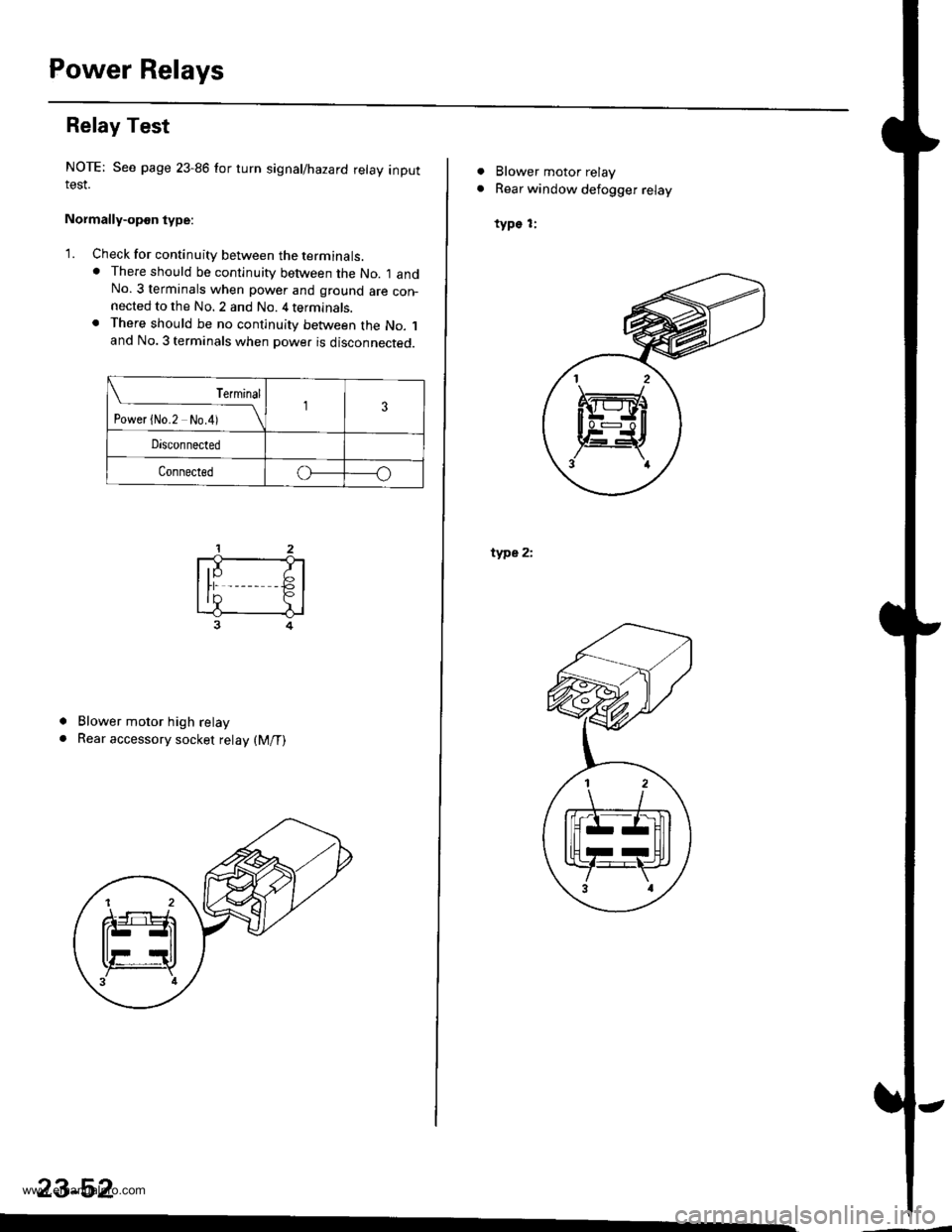
Relay Test
NOTE: See page 23-86 for turn signal/hazard relay inputIESI.
Normally-opon type:
'1. Check for continuity between the terminats.. There should be continuity between the No. I andNo. 3 terminals when power and ground are con-nected to the No. 2 and No. 4 terminals.. There should be no continuity between the No. 1and No. 3 terminals when power is disconnected.
Terminal
t"""r f *r t*i__\l3
Disconnected
Connectedo
a
a
Blower motor high relay
Rear accessory socket relay (M/T)
23-52
ffi
. Blower motor relay
. Rear window defogger relay
type 1:
type 2i
H
al 2 \
Itrrz-Hl
llHrrUll
Y:F,',3 al
www.emanualpro.com