Page 371 of 1395
ldle Speed Setting
Inspoction/Adiustmont
37 modsl:
NOTE:
. Before setting the idle speed, check the following
items:- The MIL has not been reportsd on.- lgnition timing- Spark plugs
- Air cleaner- PCV system
. lcanada) Pull the parking brake lever up. Stan the
engine, then check that the headlights are off.
1. Start the engine. Hold the engine at 3,000 rpm with
no load (in Park or neutral) until the radiator fan
comes on, then let it idle.
Connect a tachometer or a Honda PGM Tester.
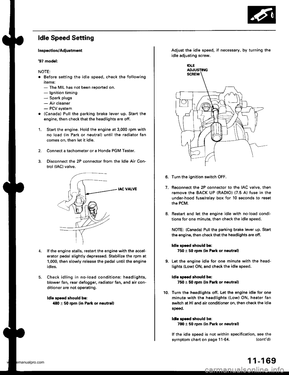
Disconnect the 2P connector from the ldle Air Con-
trol (lAC) valve.
IAC VALVE
lf the engine stalls, restart the engine with the accel-
erator pedal slightly depr6ss6d, Stabilize the rpm at
1,000, then slowly release the pedal until the engine
idles.
Check idling in no-load conditions: hsadlights,
blower fan, rear d€fogger, radiator fan, and air con-
ditioner are not operating.
ldle spood should b.:
{80 t 50 rpm {in Park or noutr.ll
IDLE
7.
Adjust the idle sp6ed,
idle adjusting screw.
if necessary, by turning the
Turn the ignition switch OFF.
Reconnect the 2P connector to the IAC valve, then
remove the BACK UP (RAD|Ol (7.5 Al fuse in the
under-hood fuse/rslav box for 10 seconds to reset
the PCM.
Restart and let the engine idle with no-load condi-
tions for one minute, then check the idle speed.
NOTE: (Canadal Pullthe parking brake lever up. Stan
the engine, then check that the headlights are off.
ldlo Ep€ed rhould be:
75O t 50 rpm (in P.rk or noutr.ll
Let the engine idl6 for one minute with the head-
lights (Low) ON, and check th€ idl€ speed.
ldle lpcod 3hould bo:
750 t 50 ]pm (in Park or nautlal)
Turn the headlights off. Let th€ engine idle for one
minute with the headlights (Low) ON, heater fan
switch at Hl and air conditioner on. then check the idle
sDeeo.
ldl. specd should b6:
7d) 1 50 rpm {in Park or nautral}
lf the idle speed is not within specification, see the
symptom chart on page 11-64. (cont'd)
1 1-169
www.emanualpro.com
Page 432 of 1395
Glutch Master Cylinder
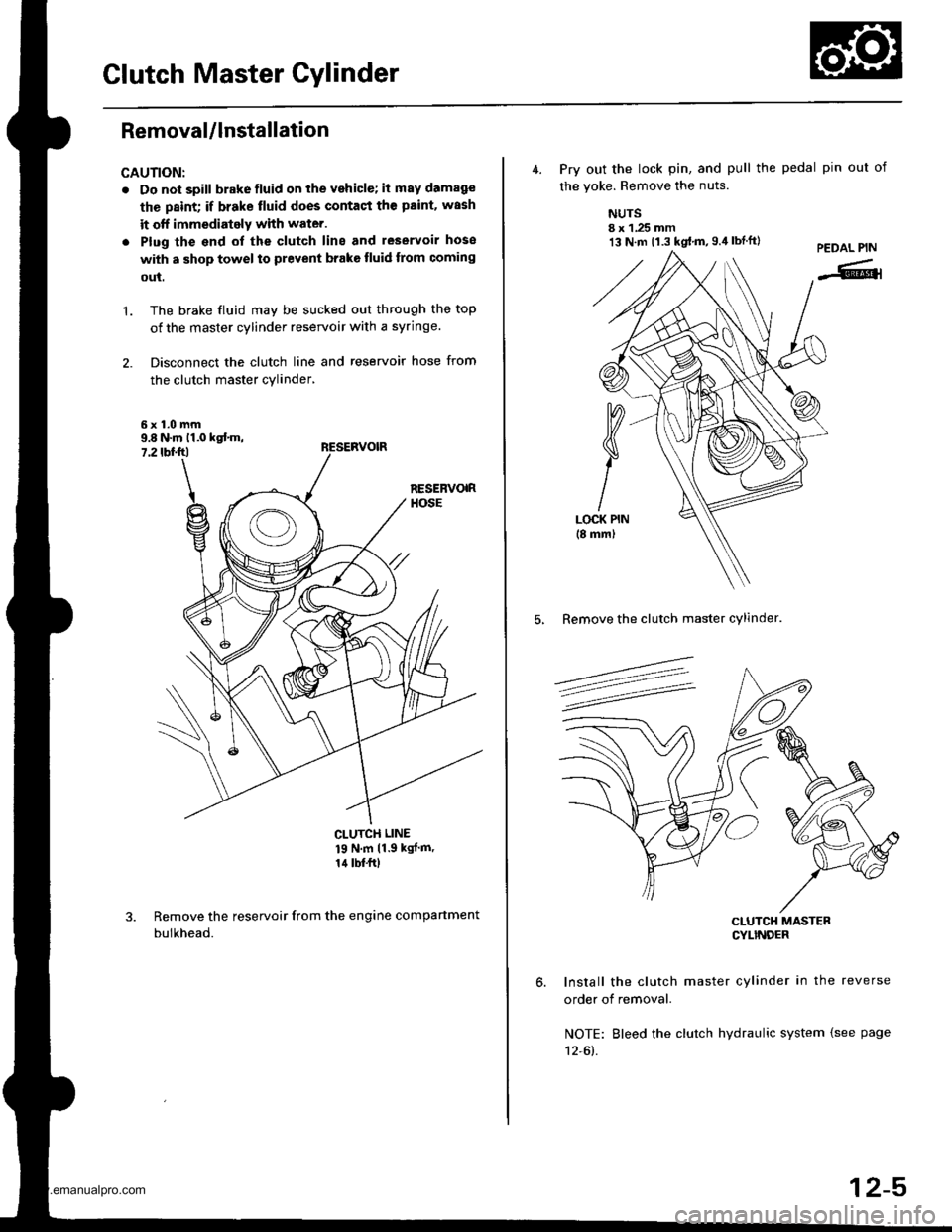
Removal/lnstallation
CAUTION:
. Do not spill brake fluid on the vehicle; it may damage
the paint; if brake tluid does contact the paint. wash
it off immediately with water.
. Plug the end ol the clutch line and leservoir hose
with a shop towel to prevent brake tluid trom coming
out.
The brake fluid may be sucked out through the top
of the master cylinder reservoir with a syringe.
Disconnect the clutch line and reservoir hose from
the clutch master cylinder,
't.
9.8 N.m 11.0 kst m,7.2 tbf.ftl
CLUTCH LINE
19 N'm 11 9 kgJ m'
14 lbf.frl
Remove the reservoir from the engine compartment
bulkhead.
13 N.m t1.3 kgt.m,g.il lbtft)
4. Prv out the lock pin, and pull the pedal pin out of
the voke. Remove the nuts.
NUTSI x 1.25 mm
5, Remove the clutch master cylinder.
CLUTCH MASTERCYLINDEF
Install the clutch master cylinder in the reverse
order of removal.
NOTE: Bleed the clutch hydraulic system {see page
12-61.
12-5
www.emanualpro.com
Page 433 of 1395
Slave Cylinder
RemovaUlnstallation
CAUTION:
. Do nol spill brake tluid on the vehicle; itmaydamage
the paint; if brake fluid do€s contast the paint, wash
it off immediately with water.. Plug the end of the clutch line with a shop towel toprevcnt brake tluid from coming out.
.6|l,Super High Temp Urea crease (p/N 08798 -
9002).
: Brake Assembly Lube or equivalent rubber
grease.
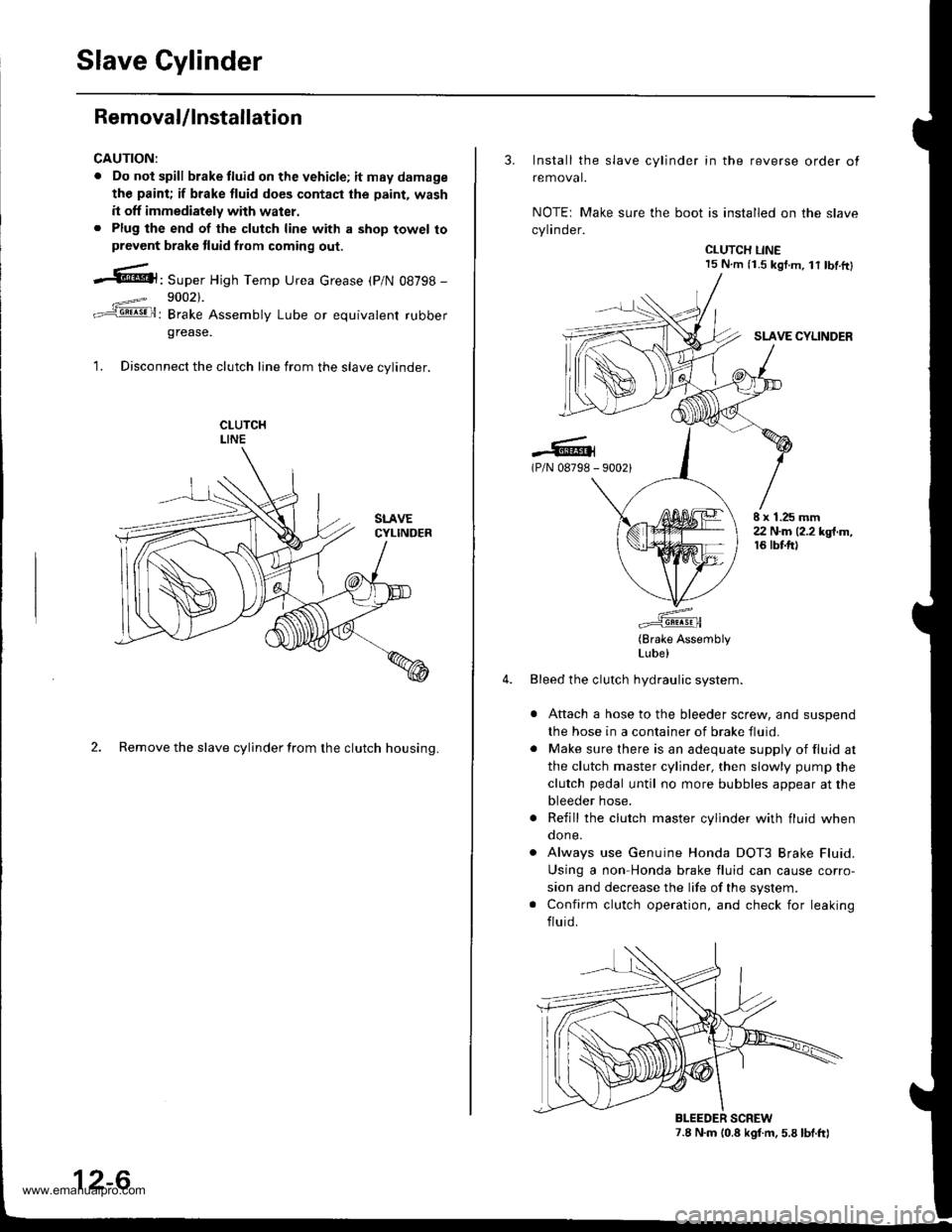
1. Disconnect the clutch line from the slave cvlinder.
2. Remove the slave cylinder from the clutch housing.
12-6
3. Install the slave cylinder in the reverse order ot
removal.
NOTEr Make sure the boot is installed on the slave
cylinder.
CLUTCH LINE15 N.m (i.S kgf.m, lt tbf.ftl
SLAVE CYLINDER
.-lG(P/N 08798 - 90021
E x 1.25 mm22 N.m (2.2 kgt.m,16 tbtft)
(Brake AssemblyLube)
Bleed the clutch hydraulic system.
Attach a hose to the bleeder screw, and suspend
the hose in a container of brake fluid.
Make sure there is an adequate supply of fluid at
the clutch master cylinder, then slowly pump the
clutch pedal until no more bubbles appear at the
bleeder hose.
Refill the clutch master cylinder with fluid whenqone.
Always use Genuine Honda DOT3 Brake Fluid.
Using a non Honda brake fluid can cause corro-
sion and decrease the life of the system.
Confirm clutch operation, and check for leaking
fluid.
7.8 N.m (0.8 kgf.m. 5.8 lbt.ft)BLEEDER SCREW
www.emanualpro.com
Page 444 of 1395
Removal
!@@ Make sure the lifts, i8cks. and safety stands
are placed properly {see section 1}.
1. Raise the front of the vehicle, and support it with
safety stands (see section 1).
2. Set the parking brake, and block both rear wheels
securely.
3. Drain the manual transmission fluid Reinstall the
drain plug with a new sealing washer.
4. Disconnect the heated oxygen sensor (HO2S) con-
nector.
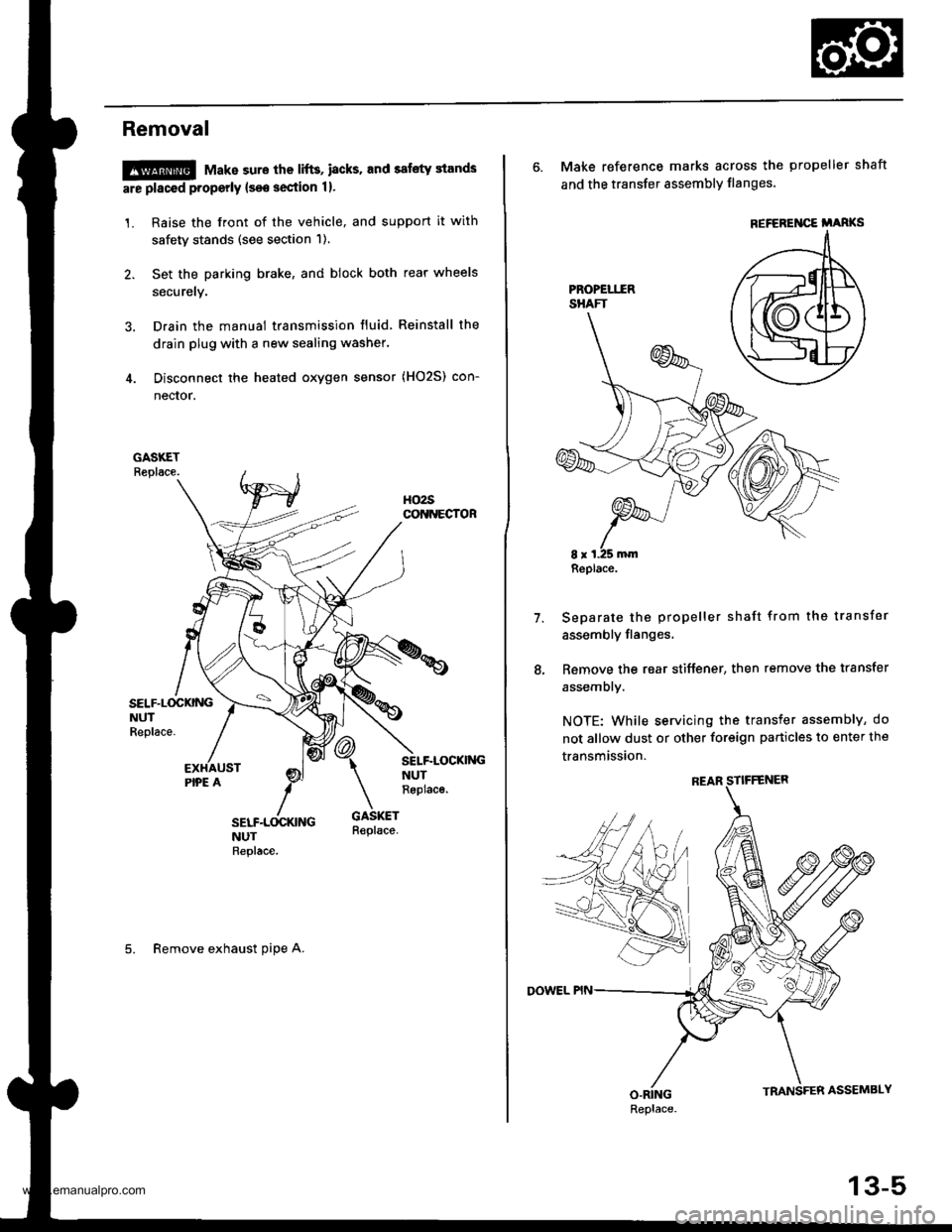
SELF.L(rcKNGNUTReplace.
SELF-LOCKI'{GNUTReplac€.
5. Remove exhaust oipe A.
6. Make reference marks across the propeller shaft
and the transfer assembly flanges'
Separate the propeller shaft from the transfer
assembly flanges,
Remove the rear stiffener, then remove the transfer
assembly.
NOTE: While servicing the transfer assembly, do
not allow dust or other foreign particles to enter the
transmission.
7.
REFEREI{CE i'ARKS
Replace.
Replace.
13-5
www.emanualpro.com
Page 446 of 1395
Transmission AssemblY
Removal
@FMak. sw. iack" and safety stands are placed propel-
ly, and hoist brackets are attached to collect position
on the engine,
. Apply parking brake and block rear wheels so vehicle
will not roll off stands and lall on you while working
under it.
CAUTION: Use fender covers to avoid damaging painted
surfaces.
1. Disconnect the negative {-) cable first, then the pos-
itive (+) cable from the batterY.
2. Remove the intake air duct and air cleaner houslng
(see section 5).
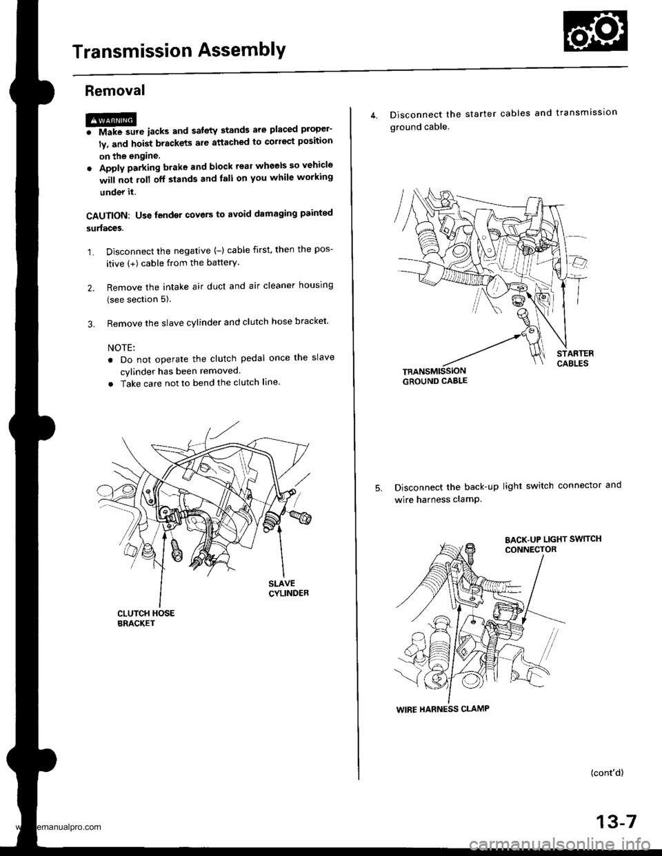
3. Remove the slave cylinder and clutch hose bracket'
NOTE:
. Do not operate the clutch pedal once lhe slave
cvlinder has been removed.
. Take care not to bend the clutch line.
4. Disconnect the
ground cable.
starter cables and transmission
TRANSMISSIONGROUND CABLE
Disconnect the back-up light switch connector and
wire harness clamP.
(cont'd)
13-7
WIRE HARNESS CLAMP
www.emanualpro.com
Page 605 of 1395
Troubleshooting Flowchart - Interlock System - Shift Lock System
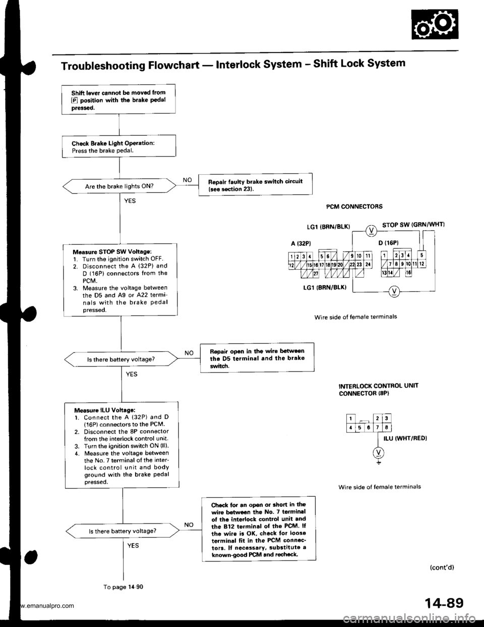
PCM CONNECTORS
Wire side of lem6le termanals
INTERLOCK CONTROL UNIT
CONNECTOR I8P)
ILU IWHT/REDI
(cont'd)
Shift lever cannot be moved from
E] position with the brake P€delpreiseo.
Chock Brake Light Operation:Press the brake pedal.
Repsir fauhy brake switch circuit
{seo s€ction 231.Are the brake lights ON?
M€asure STOP SW voltage:l Turn the ignition switch OFF.
2. Disconnect the A (32P) and
D (16P) connectors lrom thePCM.3. Measlre the voltage between
the D5 and Ag or A22 terma
nals with the brake Pedalpressed,
Repair opon in the wi.e be{w.enthe D5 terminal and the br.ke
switd!.
Measur€ ILU vohage:1. Connect the A {32P) and D
116P) connectors to the PCM.2. Disconnect the 8P connectorfrom the interlock control unit
3. Turn the ignition switch ON (ll).
4. Measure the voltage betweenthe No.7 terminalofthe inter
lock control unit and bodyground with the brake Pedalpressed,
Ch€ck for an opon or thon in the
wire Mwoon tho No. 7 terminrl
of the inte ock control unit and
the 812 termin.l of the PcM. ll
the wirs is OK, check tor loo3e
terminal fit in the PCM connec_
to13. ll nece3sary,3ubstitute a
known-good PCM and rechock.
ls there battery voltage?
To page 14 90
14-89
www.emanualpro.com
Page 642 of 1395
Electrical Troubleshooting ('98 - 00 Modelsl
Troubleshooting Flowchart - Interlock System - Shift Lock System
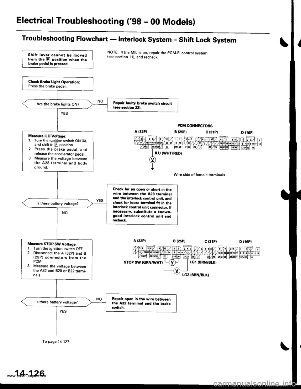
NOTE: li the MIL is on, ropair the PGM-FI controt system{see section 11), and recheck.
PCM CONNECTORS
c l3lPl
Wire side of female lerminals
c t3lPt
D {16P1
1 tttt/ 5t/ 1 a t /tlt 1 t\/t ,/ VVV tl t ttj,r\1e\10l211n . I 3 rholr1 t?m@-@Effilil"
D (lCPl
| 2ttt/ ;t /n) ).tt)/ 1 21:/ tvvvvv nnvl.lnl2
I r r ero
12wE gp]P] polr EI!l!!i r.
a (25P1
LGl {8RN/ALKI
Shift levor cannot be mov6dllom the E po3ition when th6blako pedal is pre3sed.
Ch€ck BJake Light Oporation:Press the brake pedal.
B6pair tlutty brrko 3whch circuitl..e rection 231.Are the brake lights ON?
Me.sure ILU Voltage:1. Turn the ignition switch ON (ll1,and shiftto E position.2. Press the brake pedal, andrelease the accelerator pedal.3. Measure the voltage betweenthe A28 terminal and bodygrouno.
Chock tor an open or short in thewi.o botwoen tha A28 t6rminrland thc intorlod( control unit, rndcheck tor loose torminrl fit in theintorlock conftol unh connoctor. lfnocassaryr aubstitute a known-good intollock control unit rndroch6d(
Mor3uro STOP SW vohsgo:1. Turn the ignition switch OFF.2. Disconnect the A (32P1 and B(25P) connectors {rom thePCM.3. Measure the voltage betweenthe A32 and 820 or 822 termi-nals,
Repair op6n in tho wir€ betwsenthe A32 t6.minal and th6 brake3witch.
ls there battery voltage?
fo page 14-121
14-126
www.emanualpro.com
Page 656 of 1395
A/T Gear Position Switch
Replacement
@ Make 3ure lifts, iacks, and safety stands
ar€ placod properly lsoo soction 1).
1. Raise the front of the vehicle, and support it with
safety stands (see section 1).
2. Set the parking brake, and block both rear wheels
securely.
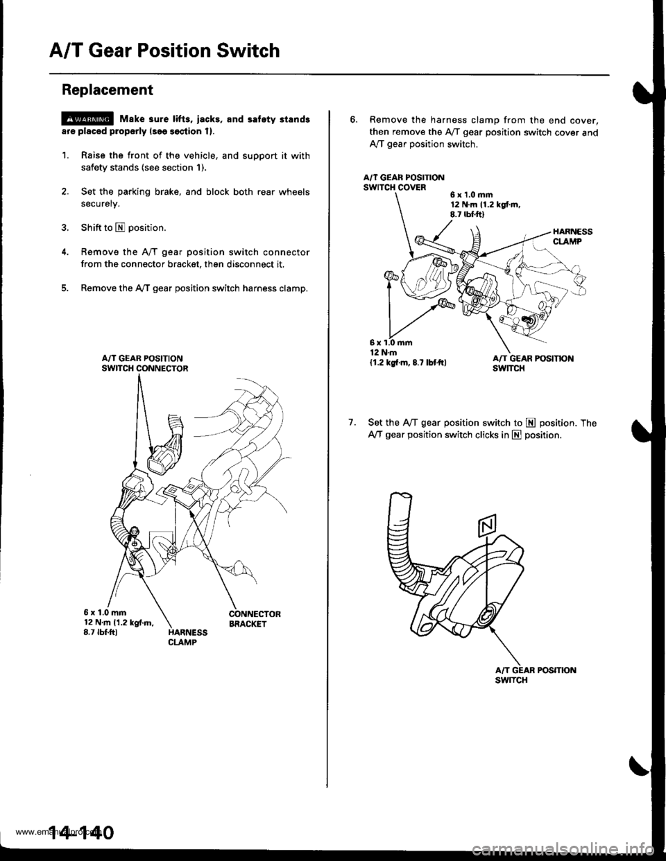
3. Shift to E position.
Remove the A/T gear position switch connector
from the connector bracket, then disconnect it.
Remove the AfI gear position switch harness clamp.
5x1.0mm12Nm11.2kgf.m,8.7 tbf.fttBRACIGT
14-140
6. Remove the harness clamp from the end cover,
then remove the Aff gear position switch cover and
Ay'T gear position switch.
A/T GEAF POSITIONswrTcH covER6x1.0mm12 N.m 11.2 kgt m.8.7 lbf.ftl
1.Set the IVT gear position switch to E position. The
AfI gear position switch clicks in E position.
POSmON
6x1.0mm12 N.m
{1.2 kg{.m,8.7 lbtftl
swlTcH
www.emanualpro.com