2000 HONDA CR-V Disc brake
[x] Cancel search: Disc brakePage 658 of 1395
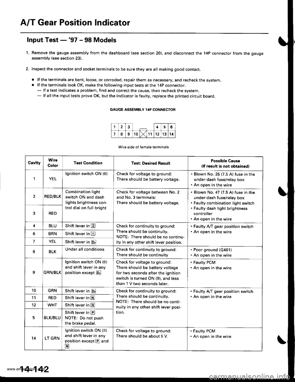
A/T Gear Position Indicator
1.
f nput Test -'97 - 98 Models
Remove the gauge assembly from the dashboard (see section 20). and disconnect the 14P connector from the gauge
assemblv (see section 23),
Inspect the connector and socket terminals to be sure they are all making good contact.
. lf the terminals are bent, loose, or corroded, repairthem as necessary, and recheck the system.. lf the terminals look OK, make the following input tests at the 14P connector.- lf I test indicates a problem, find and correct the cause, then recheck the system.- lf all the input tests prove OK, but the indicator is faulty. replace the printed circuit board,
GAUGE ASSEMBLY 14P CONNECTOR
Wire side of female terminals
CavityWirs
ColorTest ConditionTest: Desir€d ResultPossible Cause
{lf rosult is not obtainod)
YEL
lgnition switch ON (ll)Check for voltage to ground:
There should be battery voltage,
. Blown No. 25 (7.5 A) fuse in the
under-dash fuse/relay box. An open in the wire
RE D/BLKCombination light
switch ON and dash
lights brightness con-
trol dial on full bright
Check for voltage between No. 2
and No. 3 terminals;
There should be battery voltage.
Blown No. 47 (7.5 A) fuse in the
under-dash fuse/relay box
Faulty combination Iight switch
Faulty dash iight brightness
controller
An open in the wire
RED
4BLUShift lever in ECheck for continuity to ground:
There should be continuity.
NOTE: There should be no continu-
ity in any other shift lever position.
' Faulty Ay'T gear position switch. An open in the wireBRNShift lever in E
7YELShift lever in @
8BLKUnder all conditionsCheck for continuity to ground:
There should be continuity
. Poor ground {G401). An open in the wire
9GRN/BLK
lgnition switch ON {ll)
and shift lever in any
position except E
Check for voltage to ground:
There should be battery voltage
for two seconds after the ignition
switch is turned ON {ll), and less
than 1 V two seconds later,
' Faulty PCM. An open in the wire
10GRNShift lever in ECheck for continuity to ground:
There should be continuity.
NOTE: There should be no conti-
nuity in any other shift lever posi-
UOn.
. Faulty A,ff gear position switch. An open in the wire1'lREDShift lever in @
12WHTShift lever in E
BLVBLU
Shift lever in ENOTE: Do not push
the brake pedal.
14LT GRN
lgnition switch ON { ll)
and shift lever in any
position except E and
E
Check for voltage to ground:
There should be about 5 V.
. Faulty PCM. An open in the wire
14-142
www.emanualpro.com
Page 659 of 1395
L
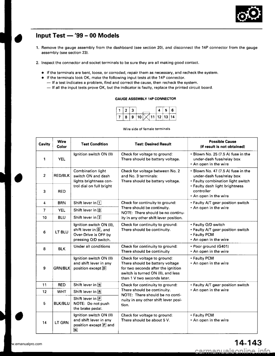
Input Test -'99 - 00 Models
Remove the gauge assembly from the dashboard {see section 20), and disconnect the 14P connector from the gauge
assembly (see section 23).
Inspect the connector and socket terminals to be sure they are all making good contact.
a lf the terminals are bent. loose, or corroded. repair them as necessary. and recheck the system.
. lf the terminals look OK, make the following input tests at the 14P connector.- lf a test indicates a problem, find and correct the cause, then recheck the system.- lf all the input tests prove OK, but the indicator is faulty, replace the printed circuit board.
GAUGE ASSEMBLY 14P CONNECTOR
Wire side of female terminals
CavityWire
ColorTest ConditionTest: Desired ResuhPossible Caus6
{lf resutt is not obtainod)
1YEL
lgnition switch ON (ll)Check for voltage to ground:
There should be battery voltage.
. Blown No.25 (7.5 A) fuse in the
under-dash fuse/relay box. An open in the wire
2RE D/BLK
Combination light
switch ON and dash
lights brightness con-
trol dial on full bright
Check for voltage between No. 2
and No.3 terminals:
There should be battery voltage.
Blown No. 47 {7.5 A) fuse in the
under-dash fuse/relay box
Faulty combination light switch
Faulty dash light brightness
controller
An open in the wire
5RED
BRNShift lever in ECheck for continuity to ground:
There should be continuity.
NOTE: There should be no continu-
ity in any other shift lever position.
. Faulty A/T gear position switch. An open in the wire7YELShift lever in E
'10BLUShift lever in E
LT BLU
lgnition switch ON (ll),
shift lever in E. and
Over-Drive is OFF bypressing O/D switch.
Check for continuity to ground:
There should be continuity.
Faulty O/D switch
Faulty A/T gear position switch
Faulty PCM
An open in the wire
8BLKUnder all conditionsCheck for continuity to ground:
There should be continuity
. Poor ground (G401)
. An open in the wire
9a:FI\|/Et| ta
lgnition switch ON (ll)
and shift lever in any
position except E
Check for voltage to groundl
There should be battery voltage
for two seconds after the ignition
switch is turned ON (ll). and less
than 1 V two seconds later.
. Faulty PCM. An open in the wire
11REDShift lever in SCheck for continuity to ground:
There should be continuity.
NOTE: There should be no conti-
nuity in any other shift lever posi-
Iton.
. Faulty A/T gear position switch. An open in the wire12WHTShift lever in E
BLI(BLU
Shift lever in ENOTE: Do not push
the brake pedal.
14LT GRN
lgnition switch ON (ll)
and shift lever in any
position except E and
E
Check for voltage to groundl
There should be about 5 V,
. Faulty PCM. An open in the wire
14-143
www.emanualpro.com
Page 660 of 1395
Interlock System
Interlock Control Unit Input Test
SRS components are located in this area. Review the SRS component locations, precautions, and procedures in the SRS
section (24) before performing repairs or service.
'1. Remove the instrument panel lower cover (see section 20).
2. Disconnect the 8P connector from the interlock control unit.
3. Inspect the connector and connector terminals to be sure they are all making good contact.
. lf the terminals are bent, loose, or corroded, repair them as necessary, and recheck the system
. lf the terminals look OK, make the following input tests at the connector.
- lf a test indicates a problem, find and correct the cause, then recheck the system
- lf all the input tests prove OK, substitute a known-good control unit, and recheck the system. lf the check is OK,
the control unit must be faulty; replace it.
NOTE: lf the shift lock solenoid clicks when the ign ition switch is tu rned ON (ll) while pressing the brake pedal withthe
shift lever in E position, the shift lock system is OK. lf the shift lever cannot be shifted from E position. test the A/T
gear position switch.
14-144
www.emanualpro.com
Page 681 of 1395
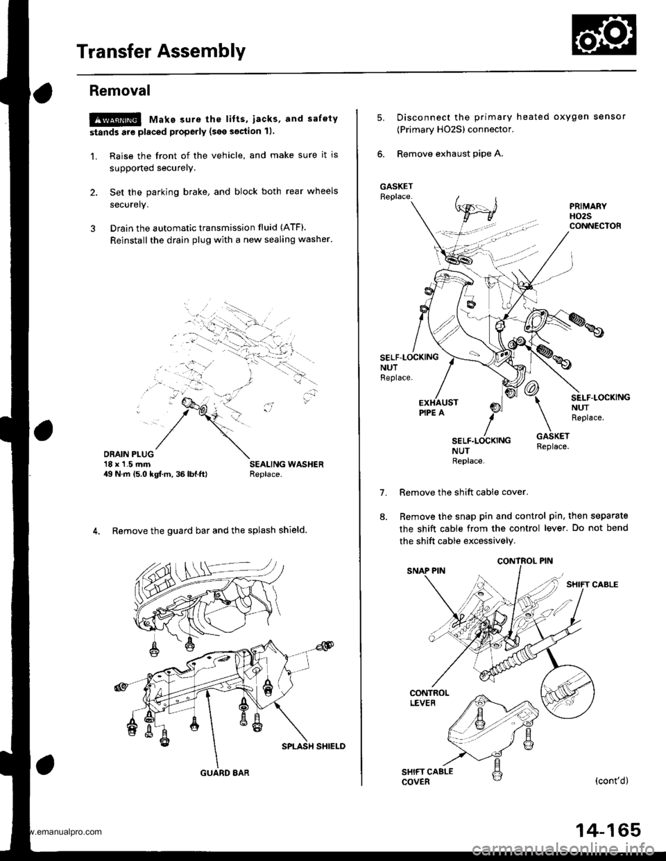
Transfer Assembly
Removal
@ Make sure the lifts, iacks, and safety
stands are placed properly (see section 11.
1. Raise the front of the vehicle, and make sure it is
supported securely.
2. Set the parking brake, and block both rear wheels
securelv.
3 Drain the automatic transmission fluid (ATF).
Reinstall the drain plug with a new sealing washer'
DRAIN PLUG'18 x'1.5 rnm49 N.m 15.0 kgf.m, 36 lbl.ftl
4. Remove the guard bar and the splash shield.
GUARD 8AR
14-165
5.Disconnect the primary heated oxygen sensor
{Primary HO2S) connector.
Remove exhaust pipe A.
SELF-LOCKINGNUTBeplace.
7.
SEI-F.LOCKINGNUTReplace.
NUTReplace
Remove the shift cable cover.
Remove the snap pin and control pin, then separate
the shift cable from the control lever. Do not bend
the shift cable excessively.
(cont'd)
www.emanualpro.com
Page 685 of 1395
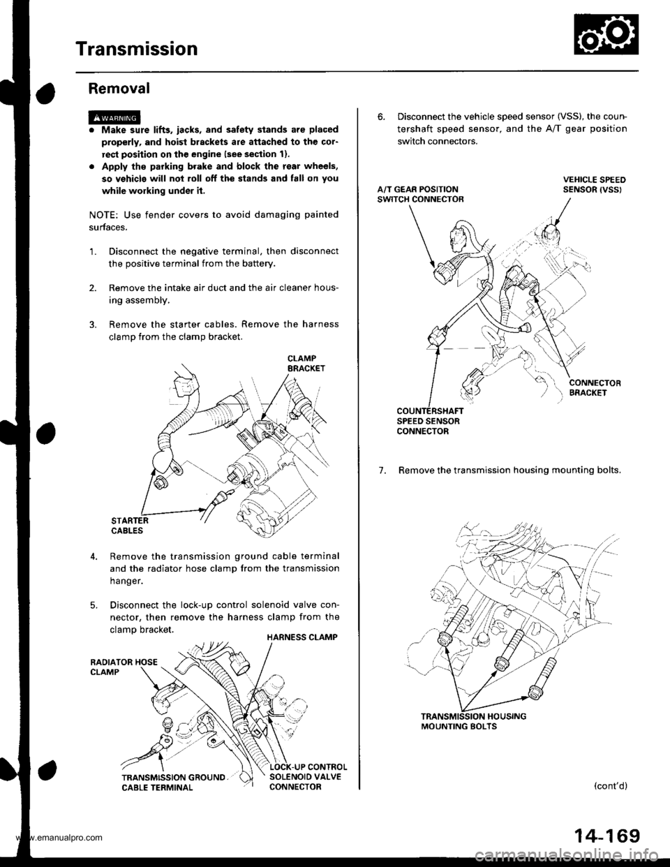
Transmission
Removal
@
2.
'1.
Make sure lifts. iacks, and safety stands aro placed
properly, and hoist brackets are attached to the col-
rest position on the engine lsee section 11.
Apply th€ parking brake and block the r€ar wheels,
so vehicls will noi roll off the stands and fall on you
while working under it.
NOTE: Use fender covers to avoid damaging painted
surfaces.
Disconnect the negative terminal, then disconnect
the positive terminal from the battery.
Remove the intake air duct and the air cleaner hous-
ing assembly,
Remove the starter cables. Remove the harness
clamp from the clamp bracket.
5.
STARTERCABLES
Remove the transmission ground cable terminal
and the radiator hose clamp lrom the transmission
hanger.
Disconnect the lock-up control solenoid valve con-
nector, then remove the harness clamp from the
clamp bracket.HARNESS CLAMP
RADIATOR HOSECLAMP
CONTROLSOLENOID VALVECONNECTOR
CLAMP
6. Disconnect the vehicle speed sensor (VSS), the coun-
tershaft speed sensor, and the A/T gear position
switch connectors.
A/T GEAR POSITIONSWITCH CONNECTOR
VEHICLE SPEEDSENSOR |VSS'
CONNECTORBfiACKET
SPEED SENSORCONNECTOR
7. Remove the transmission housing mounting bolts.
MOUNTING BOLTS
(cont'd)
14-169
www.emanualpro.com
Page 833 of 1395
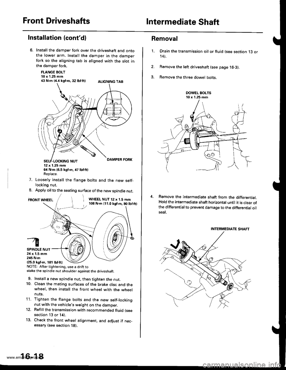
Front DriveshaftsIntermediate Shaft
Installation {cont'd}
Install the damper fork over the driveshaft and ontothe lower arm. Install the damper in the damperfork so the aligning tab is aligned with the slot inthe damper fork.
FLANGE BOLT10 x 1.25 mm€ N.m {4.i1kst.n,32 lbf.ftl ALtcNtNG TAB
12x 1.25 mm64 N.m {6.5 kgf.m, 47 lbf.ftlReplace.
7. Loosely install the flange bolts and the new self-locking nut.
8. Apply oil to the seating surface of the new spindle nut.
FRONT WHEELi WHEEL NUT 12 x 1.5 mm108 N.m (11.0 kgf.m,80lbf.ftl
SPINDLE NUT24 x 1.5 mm245 N.m{25.0 ksf.m, 181 lbf.ft)NOTE: Atter tightening. use a drift tostake the spindle nut shoulder against the driveshaft.
9. Install a new spindle nut, then tighten the nut.10. Clean the mating surfaces of the brake disc and thewheel. then install the front wheel with the wheelnuts,
1'1. Tighten the flange bolts and the new setf-lockingnut with the vehicle's weight on the damper.12. Refill the transmission with recommended fluid (see
section 13 or 14).
13. Check the front wheel alignment. and adjust if nec-essary (see section 18).
16-18
1.
Removal
Drain the transmission oil or fluid (see section 13 or14).
Remove the left driveshaft (see page 16-3).
Remove the three dowel bolts.
Remove the intermediate shaft from the differential.Hold the intermediate shaft horizontal until it is clear ofthe differentialto prevent damage to the differential oilseal.
INTERMEDIATE SHAFT
www.emanualpro.com
Page 843 of 1395
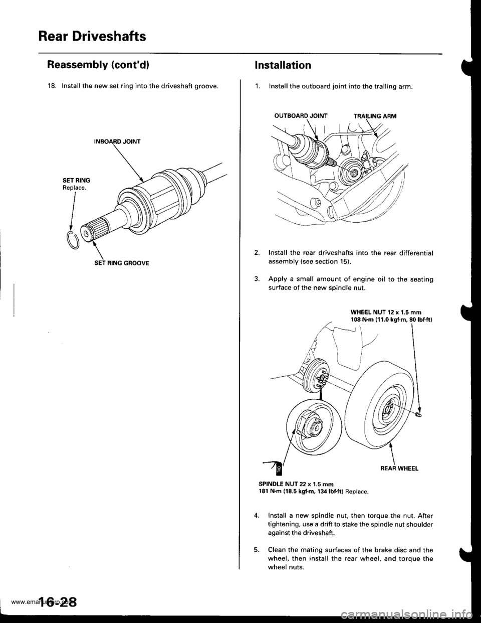
Rear Driveshafts
Reassembly (cont'd)
18. Install the new set ring into the driveshaft groove.
SET RINGReplace.
I
CI
SET RING GROOVE
16-2A
lnstallation
'1. lnstall the outboard joint into the trailing arm.
Install the rear driveshafts into the rear differential
assembly (see section 15).
Apply a small amount of engine oil to the seating
surface of the new spindle nut.
SPINDLE NUT 22 x 1.5 mm181 N.m (18.5 kgf.m, 134lbl.ftl Replace.
Install a new spindle nut, then torque the nut. After
tightening, use a drift to stake the spindle nut shoulder
against the driveshaft.
Clean the mating surfaces of the brake disc and the
wheel, then install the rear wheel, and torque the
wheel nuts.
WHEEL NUT 12 x 1.5 mm108 N.m (11.0 kgt.m, 80lbtftl
www.emanualpro.com
Page 907 of 1395
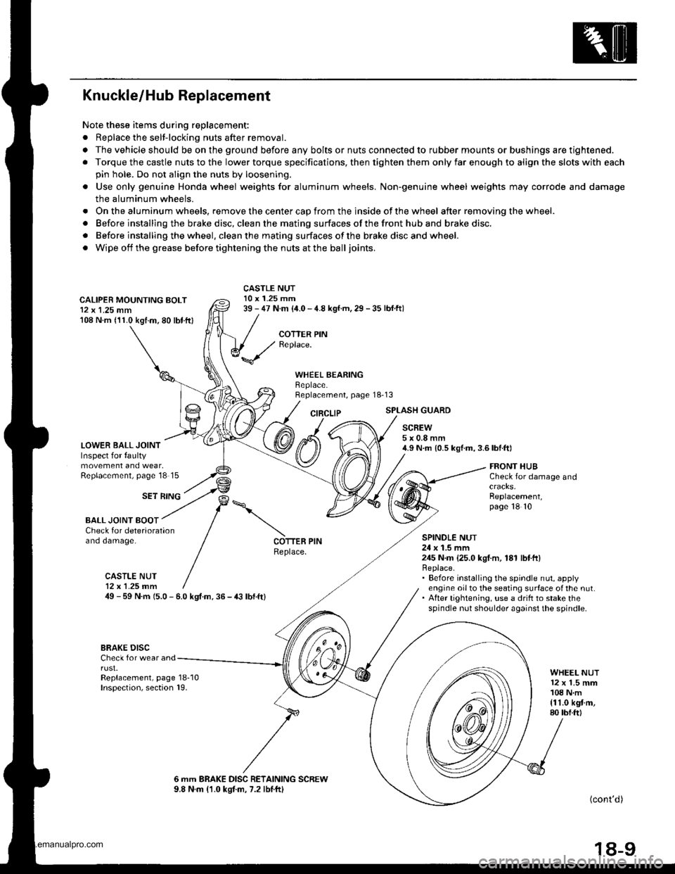
Knuckle/Hub Replacement
Note these items during replacement:
. Replace the selt-locking nuts after removal.
. The vehicle should be on the ground before any bolts or nuts connected to rubber mounts or bushings are tightened.
. Torque the castle nuts to the lower torque specifications, then tighten them only far enough to align the slots with each
pin hole. Do not align the nuts by loosening.
o Use only genuine Honda wheel weights for aluminum wheels. Non'genuine wheel weights may corrode and damage
the aluminum wheels.
. Onthealuminum wheels, remove the center cap from the inside of the wheel after removing the wheel.
. Before installing the brake disc, clean the mating surfaces of the front hub and brake disc.
. Before installing the wheel. clean the mating surfaces ofthe brake disc and wheel.
. Wipe off the grease before tightening the nuts at the balljoints.
CALIPER MOUNTING BOLT12 x 1.25 mm108 N.m (11.0 kgtm.80 lbt.ftl
LOWER BALL JOINTInspect for faultymovement and wear,Replacement, page'18 15
CASTLE NUT10 x 1.25 mm39 - 47 N.m (i1.0 - 4.8 kgf.m, 29 - 35 lbf.ftl
COTTER PINReplace.
WHEEL BEARINGBeplace.Replacement, page 18-13
CIRCLIPSPLASH GUARD
SCREW5x0.8mm4.9 N.m {0.5 kgf.m,3.6lbf.ft)
SET RING
FRONT HUBCheck for damage and
Replacement,page 18 10
BALL JOINT BOOTCheck for deteriorationano oamage.SPINOLE NUT24 x 1.5 mm245 N.m {25.0 kgI.m, 181 lbtft}Replace.. Before installing the spindle nut, applyengine oil to the seating surface of the nut.. After tightening, use a drift to stake thespindle nut shoulder against the spindle.
COTTER PINReplace.
CASTLE NUT12x 1.25 fim49 - 59 N.m 15.0 - 6.0 kgt.m. 36 - € lbf.ft)
BRAKE DISCCheck for wear andrust.Replacement, page 18-10Inspection, section 19.
WHEEL NUT12 x 1.5 mm108 N.m{11.0 kgt m,80 tbf.ftl
6 mm BRAKE DISC RETAINING SCREW9.8 N.m (1.0 kgtm, 7.2 lbtftl(cont'd )
18-9
www.emanualpro.com