Page 1081 of 1395
Wiper/Washer
Windshield Washer Tube Replacement
NOTE:
. Take care not to scratch the related parts and body.. When removing the clips, use a clip remover.
Remove the following parts.
. Left front wheelwell protector (see page 20-89). Left inner fender (see page 20-89)
WINDSHIELOWASHER NOZZLES Y-JOINT
Boute the w6sher tubesto the washer reservoir
'97 model:
63'fr{-------
ax---\J
,.&--
\7>: Clip locationsA >,2 B >,1c>, 1D>,1
\
lnstallation is the reverse of the removal procedure.
NOTE:
. Take care not to pinch the washer tubes.
. lf necessary, replace any damaged clips.. After installing, adjust the aim ofthe washer nozzles (see page 20-103).
20-100
www.emanualpro.com
Page 1082 of 1395
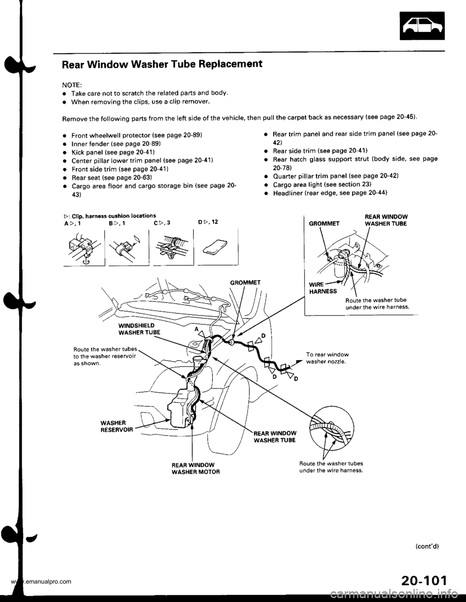
Rear Window Washer Tube Replacement
NOTE:
. Take care not to scratch the related parts and body.
. When removing the clips, use a clip remover.
Remove the following parts from the left side of the vehicle, then
. Front wheelwell protector (see page 20-89)
. Innertender (see page 20-89)
. Kick panel (see page 20-4't)
. Center pillar lower trim panel (see page 20-41)
. Front side trim (see page 20-41)
. Rear seat (see page 20-63)
a Cargo area floor and cargo storage bin (see page 20-
43)
>: Clip, harness cu3hion location3c>,3D>,12A>, 1B>, 1
Route the washer t!be
under the wire harness
Route the washer tubesto the washer reservoir
WASHEBRESERVOIR
wasner no2zre.
@s_l el 4
WINDSHIELDWASHEB TUBE
REAR WINDOWWASHER MOTOR
GROMMET
wrNoowWASHER TUBE
pull the carpet back as necessary (see page 20-45)
. Rear trim panel and rear side trim panel (see page 20-
42J
. Rear side trim (see page 20-41)
. Rear hatch glass support strut (body side, see page
20-7Al
. Ouarter pillartrim panel (see page 20-421
o Cargo area light (see section 23)
. Headliner (rear edge, see page 20-44)
GROMMET
(cont'd)
20-101
www.emanualpro.com
Page 1088 of 1395
Frame Repair Chart
(cont'd)
Side view:
Unit: mm (in.)
0: Inner diamete.
POINT d3
o15 {0.591 For Trensmission Mount
d15 10.591 For Trrnsmi3donMount
POINT d1
t13 10.5'll For Transmb3ionMount
POINT el
613 10.51) For TransmirsionMouni
z
t13 {0,511 For Engin6 Mount
M10 x Pl.25
t13 10.51) For Uppcr Arm
.25
POINT,1710.67)Fof Re.r Beam
o12 (0.,171 For Right Front Stop
POINT c1
o16 10.631 Locate Hole
612 {0.47} For Left Front Stoo
b2
r12 {0.47) For Left Front StoD
t5011.97| Locrt. Hol.
POINT
t17 10.671 Fo. R..r
r'17 10.671 For Rcar Bo.mt12 {0.47} For Right Front Stop
POINT c2
130POINT h1
DamperLower BushingPoint
o11 (0.{31 For Engine Mount
20-108
www.emanualpro.com
Page 1090 of 1395
a
Heater and Air Conditioning
Heater ...........21
NOTE: Section 21 ("Heater") is included in section 22.
Air Conditioning ......'..'.. '.'22'1
SUPPLEMENTAL RESTRAINT SYSTEM (SRS}
This model has an SRS which includes a driver's airbag in the steering wheel hub, a passenger's airbag in the dashboard
above the glove box ('97,00 models). and seat belt tensioners in the seat belt retractors ('98 - 00 models). Information
necessary to safely service the SRS is included in this Service Manual. ltems marked with an asterisk (*) on the contents
page include. or are located near, SRS components. Servicing, disassembling or replacing these items will require special
precautions and tools, and should only be done by an authorized Honda dealer.
@. To avoid rendering the SRS inoperative, which could lead to personal iniury or death in the event of 8 severe frontal
collision, all SRS service work must be performed by an authotized Honda dealer.
lmproper service procedures, including incorrect removal and installation of the SRS, could lead to personal iniury
caused by unintentional deployment of the airbags ('97 - 00 models), and seat belt tensioners 138 - 00 models).
Do not bump the SRS unit. Otherwise, the system may fail in case of a collision, or the airbags may deploy when the
ignition switch is ON {lll.
SRS eleqtrical wiring harnesses are identified by yellow color coding. Related components are located in the steering
column, front console, dashboard, dashboard lower panel, and in the dashboard above the glove box. Do not use elec-
tricaltest equipment on thes€ cilcuils.
www.emanualpro.com
Page 1145 of 1395
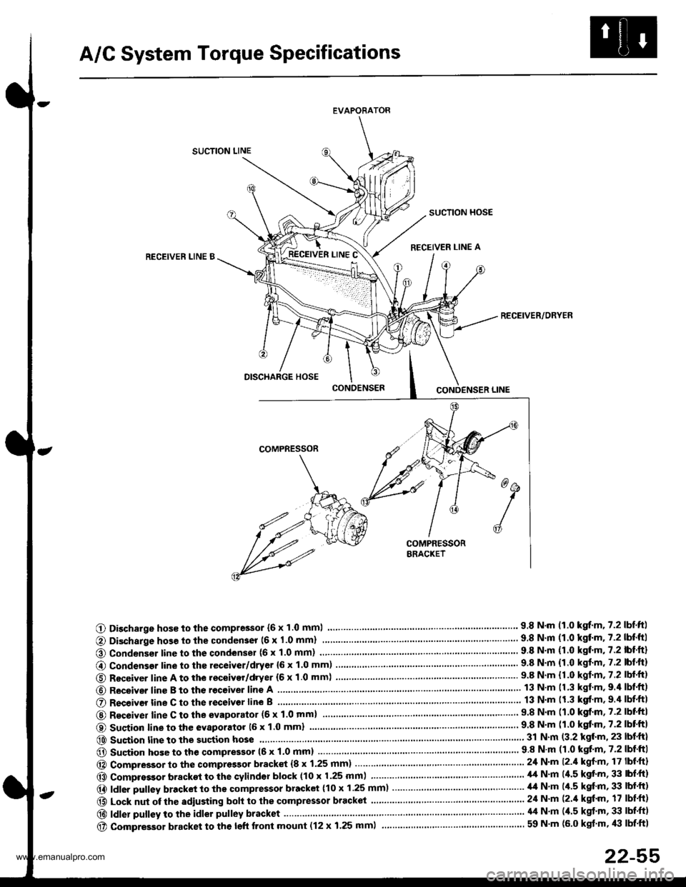
A/C System Torque Specifications
EVAPORATOR
SUCTION LINE
SUCTION HOSE
RECEIVER LINE ARECEIVEN LINE B
RECEIVER/ORYER
O Discharge hos€ to the compressor {6 x 1.0 mml.... 9.8 N.m 11.0 kgrf.m.7.2lbtftl
@ Condenser line to the condenser (6 x 1.0 mm)
@ Condensor line to the receiver/dryer {6 x 1.0 mm) ........9.8 N.m {1.0 kgf.m, 7.2 lbt.ft)
O Receiver line A to the receivor/dryer (6 x 1.0 mm) ...... ....................... 9.8 N.m {1.0 kgf.m.7.2 lbf.ft}
@ Receiver line B to th€ receive. line A
O R€ceiver tine C to the receivor line B
@ Recoiver line C to the evaporator (6 x 1'0 mml9.8 N'm (1.0 kgf.m,7.2lbtftl
O Sustion line to the evaporatot 16 x 1.0 mml
@ Sustion line to the suction hose...... 31 N.m (3.2 kgl.m, 23 lbf.ft)
@ Sucion hose to the qompressor (6 x 1.0 mm) .....'...' 9 8 N'm (1 0 kgt'm, 7'2 lbf'ftI
@ Compressor to the compressor bracket {8 x 1.25 mm) ... 24 N.m l2.il kgf'm, 17 lbf'ft}
@ Compressor bracket to the cylindsr block (10 x 1.25 mm) ................ ......... il,t N'm (4.5 kgt'm, 33 lbf'ft)
@ ldler pulley bracket to the compressor bracket (10 x 1.25 mm)..................... ,14 N.m (/r.5 kgf'm, 33 lbf'ft)
@ Lock nut of the sdiusting boh to the compressor bracket ......................... 24 N'm (2./t kgt'm, 17 lbf'ft)
@|d|erpu||eytotheid|orpu||eybracket.....'..........................'....\
.'.....'........'....44N.m(4.5kg''m'33|bf.f)
@ compressor bracket to the left front mount (12 x 1.25 mml ................... ............................ 59 N'm (6.0 kgt'm, /l:| lbf'ft1
22-55
www.emanualpro.com
Page 1146 of 1395
A/G System Service
Performance Test
The performance test will helD determine if the air con-
ditioner system is operating within specifications.
Use only service equipment that is U.L.-listed and is cer-
tified to meet the requirements of SAE J2210 to remove
HFC-134a (R-134a) from the air conditioner svstem.
CAUTION: Exposure to air condiiioner r€trigerant and
lubricant vapor or mist can irritate €yes, nose and
throat. Avoid bre8thing the air conditioner retrige.ant
and lubricant vapor or mist,
lf accidental system discharge occurs. ventilate work
area before resuming service.
R-134a service equipment o. vehicle air conditioner sys-
tems should not be pressure tested or leak tested with
comDressed air.
@ some mixtur€s ol air and R-134a have becn
shown to be combuslible at olsvated pressures and can
result in lire or explosion causing iniury or property
damage. Never use compressed air to prgssure test R-
13i[a service equipment or vehicle air conditioner sys.
tems.
Additional health and safety information may be obtained
from the refrigerant and lubricant manufacturers.
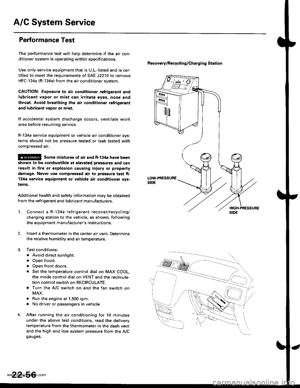
Recovory/Recycling/charging station
LOW.PRESSURESIDE
1.Connect a R-134a refrigerant recover/recycling/
charging station to the vehicle, as shown. following
the equipment manufacturer's instructions,
Insen a thermometer in the center air vent. Determine
the relative humidity and air temperature.
Test conditions:
. Avoid direct sunlight.
o Open hood.
. open front doors.
. Set the temperature control dial on MAX COOL,
the mode control dial on VENT and the reci.cula-
tion control switch on RECIRCULATE.
. Turn the A,/C switch on and the fan switch on
MAX.
. Run the engine at 1,500 rpm.
. No driver or passengers in vehicle
After running the air conditioning for 10 minutes
under the above test conditions, read the deliverv
temperature from the thermometer in the dash vent
and the high and low system pressure from the Ay'Cgauges.
2.
22-56
www.emanualpro.com
Page 1152 of 1395
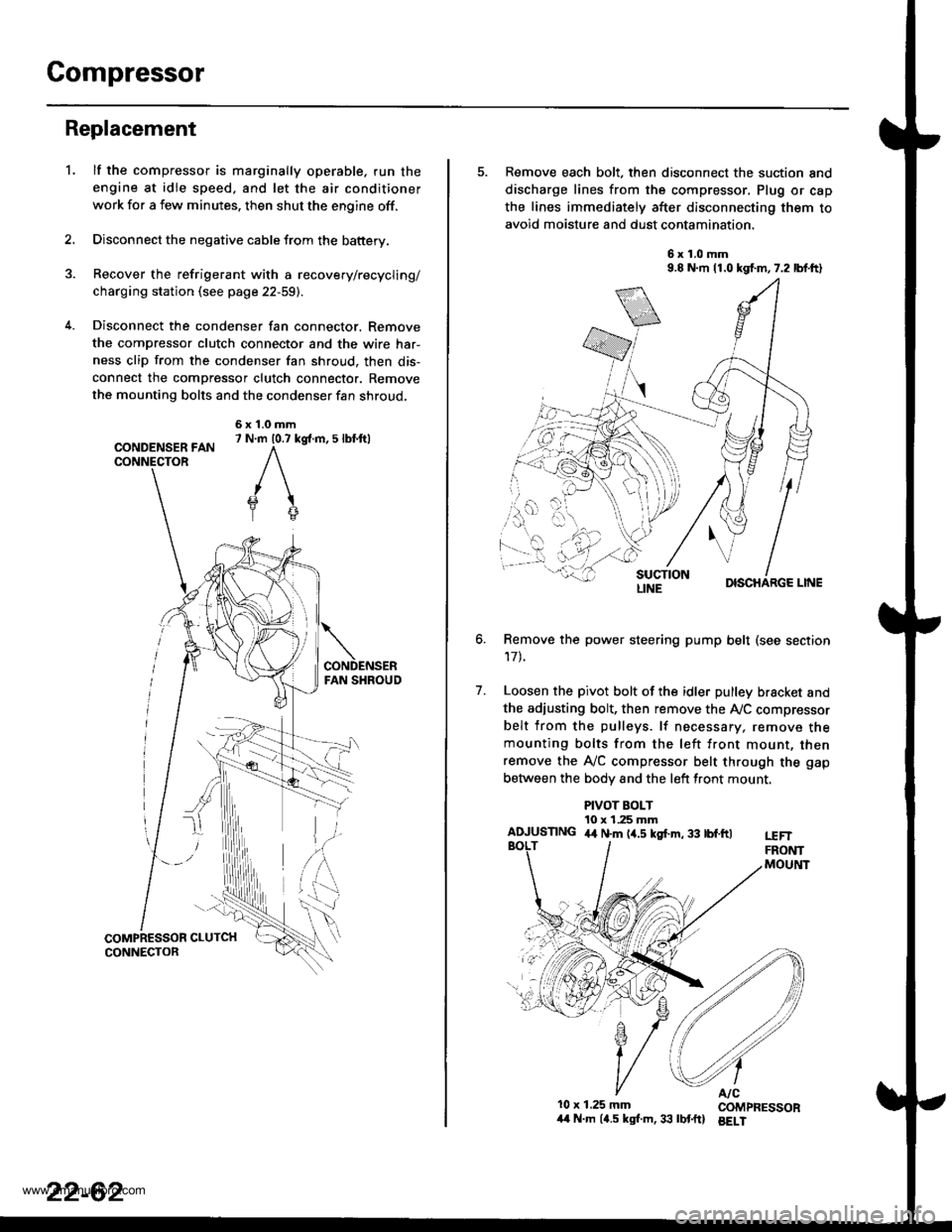
Compressor
Replacement
lf the compressor is marginally operable. run the
engine at idie speed, and let the air conditioner
work for a few minutes. then shut the engine off.
Disconnect the negative cable from the battery.
Recover the refrigerant with a recovery/recycling/
charging station (see page 22-59).
Disconnect the condenser fan connector. Remove
the compressor clutch connector and the wire har-
ness clip from the condenser fan shroud, then dis-
connect the compressor clutch connector. Remove
the mounting bolts and the condenser fan shroud,
CONDENSER FANCONNECTOR
6x1.0mm7 N.m 10.7 kg{.m, 5 lbl.ftl
'L
2.
5. Remove each bolt, then disconnect the suction and
discharge lines from the compressor. Plug or cap
the lines immediately after disconnecting them to
avoid moisture and dust contamination,
6x1.0mm9.8 N.m 11.0 kgf.m,7.2 lbf.ft)
DISCHARGE LINE
Remove the power steering pump belt (see section
17t.
Loosen the pivot bolt of the idler pulley bracket and
the adiusting bolt, then remove the Ay'C compressor
belt from the pulleys. lf necessary, remove themounting bolts from the left front mount, thenremove the A,/C compressor belt through the gap
between the bodv and the left front mount.
6.
7.
PIVOT BOLT10 x 1.25 mmAIUUSTING 4,t N.m (4.5 kgf.m, 33 tbf.ftlt€FTFRONTMOUltlT
10x 1.25 mm COMPRESSOR/t4 N.m (4.5 kgl.m,33 lbtftl BELI
LINE
www.emanualpro.com
Page 1153 of 1395
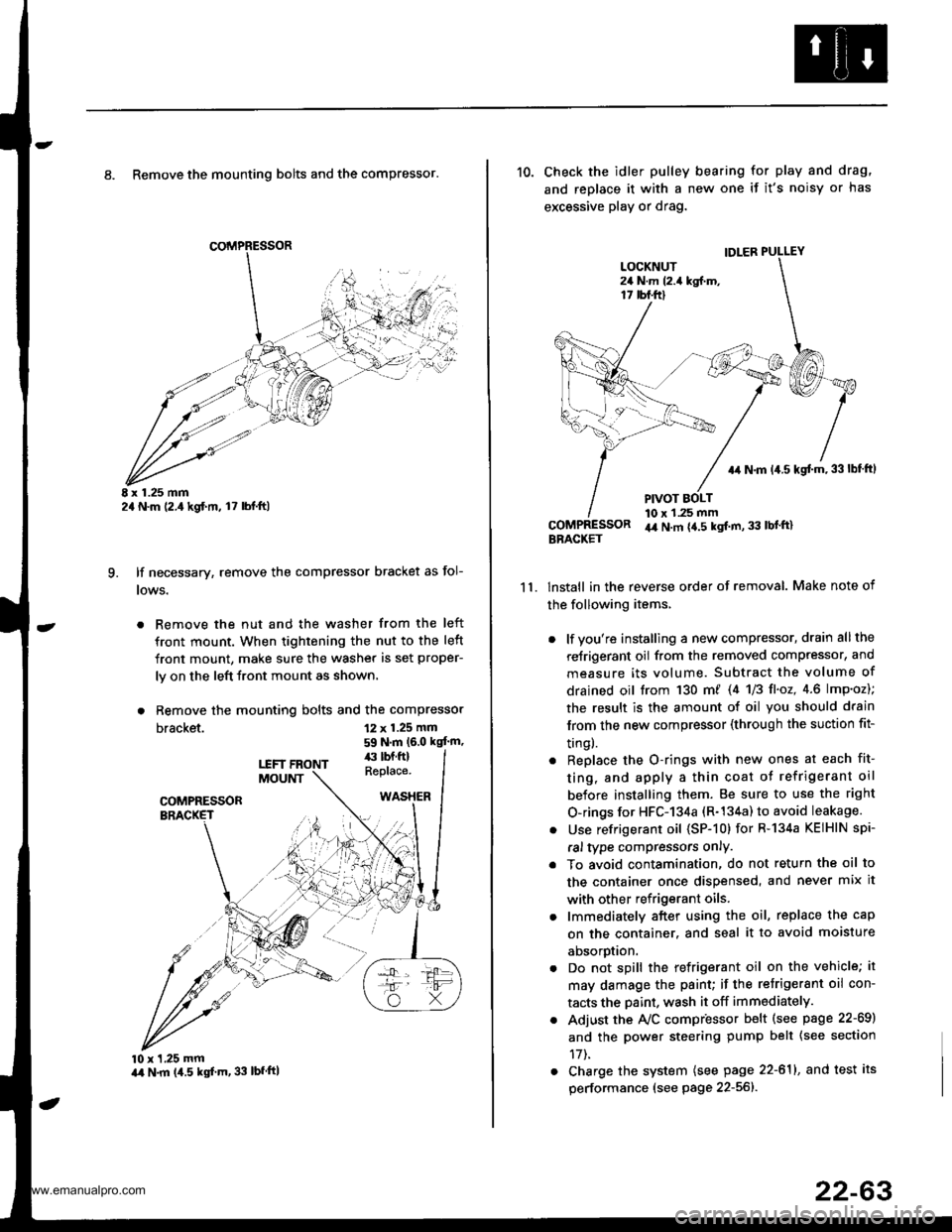
8. Remove the mounting bolts and the compressor.
E x 1.25 mm2a N.m (2.,1kgf.m, l7 lbl.ft)
lf necessary, remove the compressor bracket as fol-
lows.
. Remove the nut and the washer from the left
front mount. When tightening the nut to the left
front mount, make sure the washer is set proper-
ly on the left front mount as shown.
. Remove the mounting bolts and the compressor
bracket.
q
12 x 1.25 mm
59 N.m (6.0 kgt'm,
10 x 1,25 mmart N.m (4.5 kgf'm, 33 lbfftl
11.
10. Check the idler pulley bearing for play and drag,
and replace it with a new one if it's noisy or has
excessive play or drag.
lnstall in the reverse order of removal. Make note of
the following items,
. lf you're installing a new compressor, drain all the
reJrigerant oil from the removed compressor, and
measure its volume. Subtract the volume of
drained oil trom 130 m/ 14 U3 fl'o2,4.6 lmp'oz);
the result is the amount of oil you should drain
lrom the new compressor (through the suction fit-
trngl.
. Replace the O-rings with new ones at each fit-
ting, and apply a thin coat o{ refrigerant oil
before installing them. Be sure to use the right
O-rings for HFC-134a (R-134a) to avoid leakage.
. Use refrigerant oil (SP-10) for R-134a KEIHIN spi-
ral type compressors only.
. To avoid contamination, do not return the oil to
the container once dispensed, and never mix it
with other refrigerant oils.
. lmmediately after using the oil, replace the cap
on the container. and seal it to avoid moisture
aDsorprlon.
. Do not spill the refrigerant oil on the vehicle; it
may damage the paint; if the retrigerant oil con-
tacts the Daint, wash it off immediately.
. Adjust the Ay'C compr'essor b€lt (see psge 22-69)
and the power steering pump belt {see section
17t.
. Charge the system (see page 22-611, and test its
performance (see page 22-56]-.
IDLER PULLEY
+r N.m 14.5 kgt m,33lbf ftl
PIVOT BOLT10 x 1.25 mmir4 N.m {4.5 kgt m, 33 lbl'ft}BBACKET
www.emanualpro.com