Page 103 of 1395

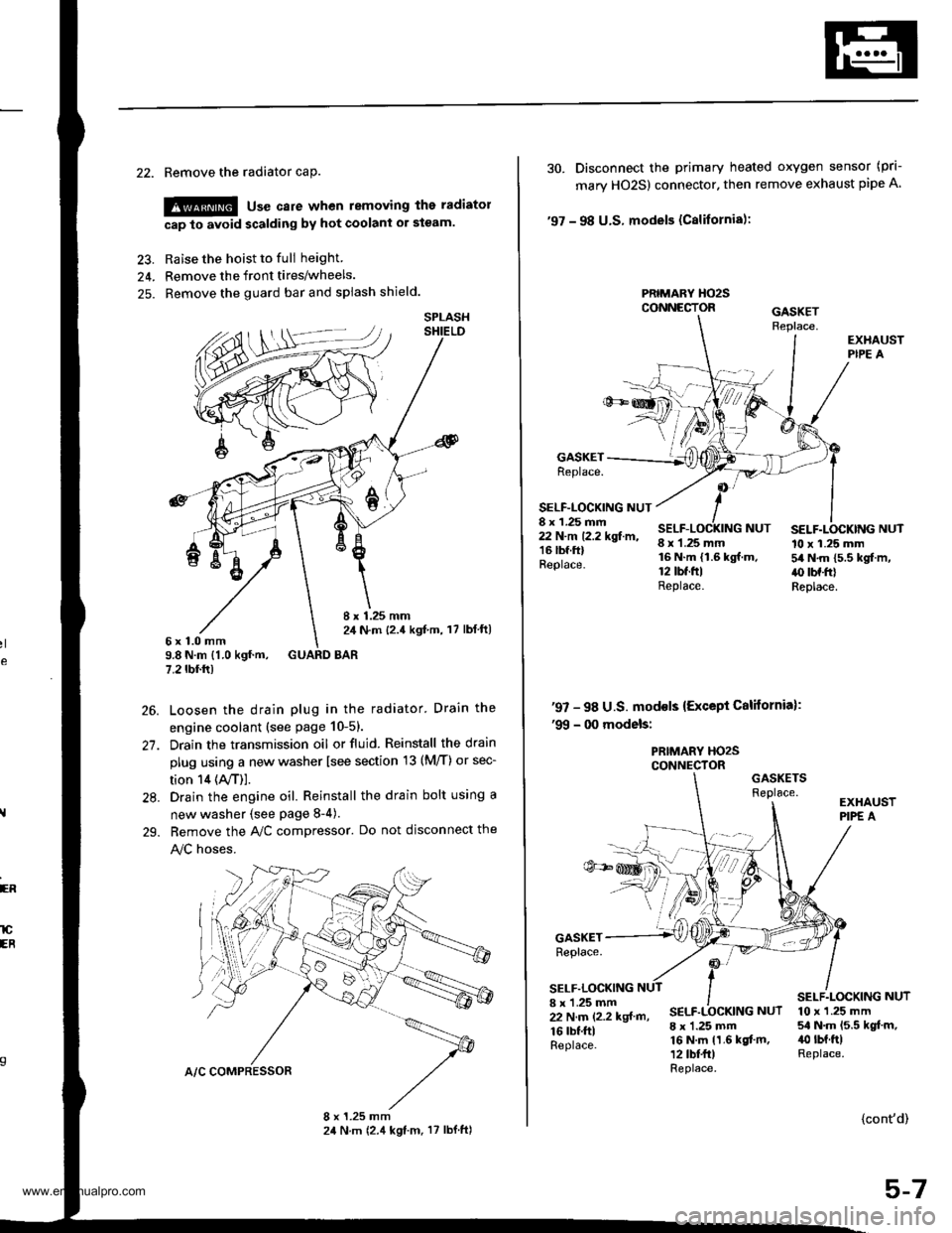
22. Remove the radiator caP.
!@ use care when removing the radiatol
cap to avoid scalding by hot coolani or steam.
23. Raise the hoist to full height
24. Remove the front tires/wheels.
25. Remove the guard bar and splash shield.
8 x 1.25 mm2,1 N.m {2.4 kgf,m, 17 lbl ft)6x1.0mm9.8 N.m {1.0 kgf.m, GUARD BAR7.2 tbf.rr)
Loosen the drain plug in the radiator. Drain the
engine coolant (see page 10-51.
Drain the transmission oil or fluid. Reinstall the drain
plug using a new washer lsee section 13 (M/T) or sec-
tion 14 (ly'T)].
Drain the engine oil. Reinstall the drain bolt using a
new washer {see page 8-4).
Bemove the A,/C compressor. Do not disconnect the
!y'C hoses.
SPLASH
26.
27.
28.
29.
ER
lCEB
30. Disconnect the primary heated oxygen sensor (prl-
mary HO2S) connector. then remove exhaust pipe A
'97 - 98 U.S. models (Cslifornia):
PRIMARY HO2SCONNECTOR
GASKETReplace.
SELF-LOCKING NUT8 x 1.25 mm22 N.m 12.2 kgf.m,16 lbf.ftlReplace.
8 x 1.25 mm16 N.m {1.6 kgf.m.12 tbt.ftlReplace.
SELF.LOCKING NUT10 x 1.25 mm54 N.m 15.5 kgf.m,.() tbf.frlReplace.
NUT
'97 - 98 U.S. mod€ls {Except California):'99 - 00 models:
PRIMARY HO2SCONNECTORGASKETSReplace.
GASKETReplace.
SELF.LOCKING8 x 'l.25 mm22 N.m (2.2 kgf m,
16 rbf.ftlReplace.
SELF.LOCKING NUT
8 x 1.25 mm16 N.m 11.6 kgf.m,12 tbt fr)Replace.
10 x 1.25 mm54 N.m 15.5 kgt.m,40 rbt.ftlReplace.
{cont'd)
5-7
www.emanualpro.com
Page 132 of 1395

13. Remove the upper radiator hose, heater hose and
water bypass hose.
WATER BYPASS
UPPEBRADIATORHOSE
17
HEATERHOSE
Remove the engine wire harness connectors and
wire harness clamps from the cylinder head and the
intake manifold.
o Four fuel injector connectors
. Engine coolant temperature (ECT) sensor con-
neclor
. Radiator fan switch connector
. Coolant temperature gauge sendlng unlt connec-
tor
. Throttle position sensor connector
. Manifold absolute pressure {MAP) sensor con-
nector
Primary heated oxygen sensor (primary HO2S)
connector
ldle air control (lAC) valve connector
Distributor connector
Remove the spark plug caps and distributor from the
cylinder head.
Remove the cruise control actuator (see section 4).
Support the engine with a jack, then remove the
upper bracket. Make sure to place a cushion
between the oil pan and the iack (see page 6-10).
a
18. Remove the cylinder head cover.
19. Inspect the timing belt (see page 6-9).
CYLINDER
(cont'd)
6-19
www.emanualpro.com
Page 183 of 1395
Intake Manifold
Replacement
NOTE:
. Use new O-rings and gaskets when reassembling.
. Check for folds or scratches on the surface of the gasket.
. Replace with a new gasket if damaged.
'97 - 98 models:
INTAK€ MANIFOLDReplace if cracked orif mating surfaces areoamageo,
INTAKE AIRTEMPERATURE
{IATI SENSOR22 N.n 12.2 kgl.m,16 rbf.ftl
8 x 1.25 mm22 N.m 12.2 kgtm.'t6 tbf ft)
8 x 1.25 mm22 N.m |.2.2 kgl.rn,'16 tbt ftl
I x 1.25 mm24 N m 12.4 kgf m.17 tbf.ft)
INTAKBRAC}
INTAKE MANIFOLOBRACKET B ('98 modell8 x 1.25 mm23 N m (2.3 kgt m,17 tbf.ftlI x 1.25 mm24 N.m 12.4 kgf.m,17 tbf.ft)
8 x 1.25 mm24 N.m (2.4 kgf.m,17 tbf.ft)
9-2
www.emanualpro.com
Page 184 of 1395
'99 - O0 modol3:
6x1.0mm9.8 N.m 11.0 kg{.m,7.2 tbtltl
NESONATOR
6x1.0mm9.8 N.m {1.0 kgf.m,7.2 rbr.ftt
O-RINGReplace.Apply oil to O-RINGbetore installing.
RESONATORCHAMBERBRACKET
GASKETReplace.
IAT SENSOR2:2N.m l2.2kgl.n,16 tbtftl
O.RINGReplace.
l
O.RINGReplace.
8 x 1.25 mm24 N.m 12.4 kgt m,17 tbt frl
INTAKE MANIFOLDReplace it cracked orif mating surfaces areoamageo.
8 x 1.25 mm22 N.m 12.2 kgl.m,16 rbf.ftt
IAC VALVE
8 x 1.25 mm23 N.m (2.3 kgf.m,17 tbf.ft,
INTAKE MANIFOLD
22 N.m 12,2 kgl.m,16 rbfftl
("\"- K\*}Gt
W\qu u
N,1\J 'n\
.a,,-\\J "
G)s
BRACKET
9-3
www.emanualpro.com
Page 198 of 1395
Water Pump
lllustrated Index
ENGINE COOLANTTEMPERATURE IECTISENSOR18 N.m 11,8 kgt.m,13 tbt.ftl
COOLANTTEMPERATUREGAUGEUNIT
6x1.0mm9.8 N'm (1.0 kgf.m,7.2 tbt frl
9 N.m {0.3 kgf.m,7 tbf.fttApply liquid gasketto the threads.
WATER OUTLETCOVERApply liquid gasker part No.087'18 - 0001 or 08718 - 0003to the mating surface.
RADIATOR FAN SWITCH2il N.m (2.i1 kgl.m,17 tbfft)
WATER PUMPlnspection, page 10-11
O-RINGReplac€.
6xl,0mm12 N.tn n.2 lgl.rn,8.7 tbf'ft)
CONNECTINGPIPE
6x1.0mm12 N.m 11.2 kgf.m,8.7 tbtftl
10-10
www.emanualpro.com
Page 206 of 1395
Component Locations
lndex
'97 - 98 models:
MANIFOLD ABSOLUTEPRESSURE IMAP} SENSORTroubleshooting, Page 1 1-90
THROTTLE POSITION (TP}
SENSORTroubleshooting, page 1 1-103
toLE AtR CONTROL llAcl VAI-VE
Troubleshooting, page 1 1-152
EVAPORATIVE EMISSION (EVAP)
CONTROL CANISTER VENT SHUTVALVE t'98 mod€llTroubleshooting, page 11'213
INTAKE AIR TEMPERATUREIIATI SENSORTroubleshooting. page 1 'l -95
ELECTRICAL LOADDETECTOR IELD) (USA modol)Troubleshooting, page 1 1-138
VEHICLE SPEEDSENSOR (VSS)
Troubleshooting,page 11'135
CRANKSHAFTPOSTTtON/
POWER STEERING PRESSURElPsPl swtrcHTroubloshooting, page 1 1-162
TOP OEAD CENTER/CYLINDERPOStTtON{CKP/TDC/CYP} SENSOR(Built into the distributor)Troubleshooting, page 1 l-131
CMNKSHAFT SPEEDFLUCTUATION ICKF} SENSORTroubleshooting. page 1'!-142
ENGINE COOLANTTEMPERATUREIECTI SENSORTroubleshooting, page 11 99
EVAPORATIVEI€VAP) PURGE CONTROLSOLENOID VALVETroubf eshooting, page 1 1'2o5, 213
(cont'd)
11-3
www.emanualpro.com
Page 207 of 1395
Component Locations
Index (cont'dl
39 - 00 models:
MANIFOLD ABSOLUTEPRESSURE IMAPISENSORTroubleshooting, page 1 1-90
THROTTLE POSITION {TP)SENSORTroubleshooting, page 1 1-103
IDLE AIR CONTROL OACI VALVETroubleshooting, page 1 1-152
EVAPOBATIVE EMISSION {EVAPICONTROL CANISTER VENT SHUTVALVETroubleshooting, page 1 1-213
EVAPORATIVE EMISSION(EVAPI PURGE CONTROI-SOLENOID VALVETroubleshootang, page 1 1-2'13
ELECTRICAL LOAOOETECTOR {ELD) IUSA modet)Troubleshooting, page I 1-138
INTAKE AIR TEMPERATURE(IAT) SENSORTroubleshooting, page 11 95
POWEB STEERING PRESSUREtPsPt swtTcHTroubleshooting, page 11 162VEHICLE SPEEDSENSOR IVSSITroubleshooting,page 11'135
CRANKSHAFTPOSTTTON/TOP OEAD CENTER/CYLINDERPOStTtON{CKP/TDC/CYP) SENSOR(Built into the distributor)Troubleshooting, page 11 131
CRANKSHAFT SPEEDFLUCTUATION ICKN SENSORTroubleshooting, page 1 1-142
SENSORTroubleshooting, page '11 130
ENGINE COOLANTTEMPERATURE{ECT)SENSORTroubleshooting, page 11 99
11-4
www.emanualpro.com
Page 215 of 1395

System Description
I
I
I
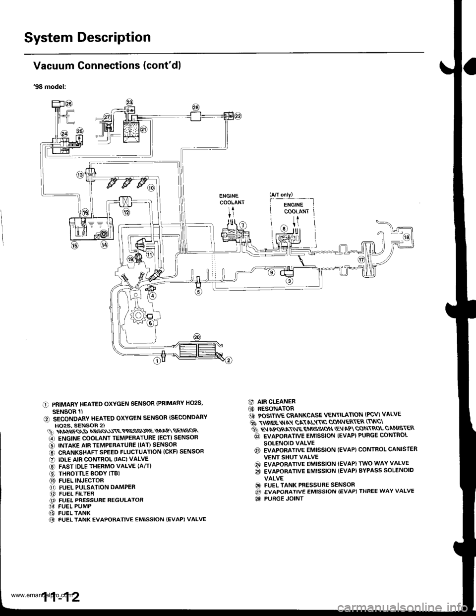
Vacuum Connections (cont'dl
'98 model:
C PRIMARY HEATEO OXYGEN SENSOR (PRIMARY HO2S,
SENSOR 1)(, SECONDARY HEATEO OXYGEN SENSOR ISECONDARYHO2S, SENSOR 2)(!)\\\\ss\SNBSS\\\ETRESS\RE\\NQ\SE\SSR
G) ENGINE COOLANT TEMPERATUBE (ECT) SENSOR
O INTAKE AIR TEMPERATURE {IAT} SENSOR
@ CRANKSHAFT SPEED FLUCTUATION (CKFI SENSOR
O IDLE AIR CONTROL (IAC) VALVE
@ FAST IDLE THERMO VALVE (A/T)
O THROTTLE BODY (TBI(0) FUEL INJECTOR.1' FUEL PULSATION DAMPER.14 FUEL FILTER(i FUEL PRESSURE REGULATOR14 FUEL PUMP(D FUEL TANK@ FUEL TANK EVAPORATIVE EMISSION {EVAPI VALVE
C] AIR CLEANER(O RESONATOR1iC POSITIVE CRANKCASE VENTILATION (PCV) VALVE
6 \$REE$IN gN NL$\C CON\ER\ER (TNC\
ti q rpos,xr E qN
ssros \E aP cqN\RoLcaNtsr€R
@ EVAPORATIVE EMISSION IEVAP) PURGE CONTROL
SOLENOID VALVEq3 EVAPORATIVE EMISSTON IEVAP} CONTROL CANISTER
VENT SHUT VALVE
@ EVAPORATIVE EMISSION (EVAP) TWO WAY VALVE
€i EVAPORATIVE EMISSION {EVAP) BYPASS SOLENOID
VALVE
€9 FUEL TANK PRESSURE SENSOROi EVAPORATIVE EMISSION {EVAP) THREE WAY VALVE
Qd PURGE JOINT
G/T only)
f
-i*'";-t
COOLANT Jt
U
11-12
www.emanualpro.com