Page 543 of 2189

Emission Control System
Evaporative Emission (EVAP) Gontrols (cont'd)
'99 - 0O models only:
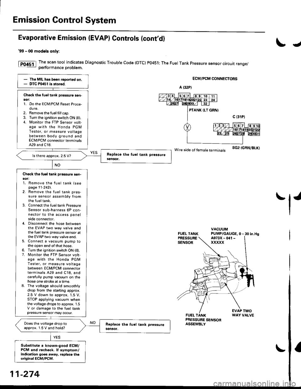
The scan tool indicates Diagnostic Trouble Code (DTC) P0451: The Fuel Tank Pressure sensor circuit range/oerformance Droblem.
ECM/PCM CONNECTORS
wire side ot femare terminars sG2 IGRN/BLK)
FUEL TANKPRESSURESENSOR
VACUUMPUMP/GAUGE,0 - 30 in.Hg
FUEL TANKPRESSURE SENSORASSEMBLY
EVAP TWOWAY VALVE
IJ
tl'
Ths MIL has been reDortgd on.DTC m/$1 i3 stored.
Check the tuel tank pros3ure ser|-sor:1. Do the ECM/PCM Reset Proce-dure.2. Remove the tuellill cap.3. Turn the ignition switch ON (ll).4. N4onitor the FTP Sensor volt-age with the Honda PGMTester, or measure voltagebetween body ground andECN4/PCM connector terminalsA29 and C18.
ls there approx. 2.5 V7
Check tho tuel tank pressure !on-soa:1. Remove the fuel tank (seepage 11 2421.2. Remove the fuel tank pres-sure sensor assembly fromthe fueltank.3. Connect the fuel tank PressureSensor sub-harness 6P con-nector to the access panelside connector,4. Disconnect the hose betweenthe EVAP two way valvg andthe fuel tank pressure sensor atthe EVAP two way valve end.5. Connect a vacuum pump tothe open end ofthat hose.6. Turn the ignition switch ON (ll).7. Monitor the FTP Sensor volt,age with the Honda PGMTester, or measure voltagebetween ECM/PCM connectorterminals A29 and C18, andcarefully pump vacuum on thehose one stroke at a time.8. The voltage sho!ld smoothlydrop from the stading approx.2.5 V down to approx. '1.5 V.STOP applying vacuum whenthe voltage drops to approx. 1.5V or damage to the fuel tankpressure sensor may occur.
Does the voltage drop toapprox. 1.5 V and hold?
Sub3titute a known-good ECM/PCM and r6check. It symptom/indicltion 90e3 aw.y, replac\. th€original ECM/PCM.
A (32P)
A973X - 041 -
xxxxx
11-274
Page 584 of 2189

Troubleshooting
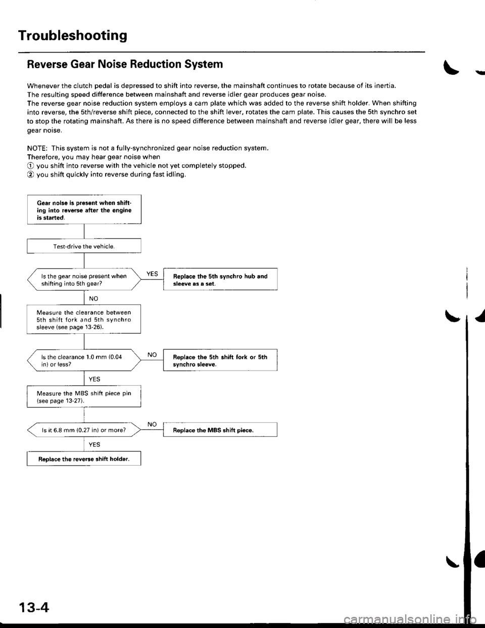
Reverse Gear Noise Reduction System
Whenever the clutch pedal is depressed to shift into reverse, the mainshaft continues to rotate because of its inertia.
The resulting speed difference between mainshaft and reverse idler gear produces gear noise.
The reverse gear noise reduction system employs a cam plate which was added to the reverse shift holder. When shifting
into reverse, the sth/reverse shjft piece, connected to the shift lever, rotates the cam plate. This causes the sth synchro set
to stop the rotating mainshaft. As there is no speed difference between mainshaft and reverse idler gear, there will be less
gear norse.
NOTE: This system is not a fully-synchronized gear noise reduction system.
Therefore, you may hear gear noise when
O you shift into reverse with the vehicle not yet completely stopped.
@ you shift quickly into reverse during fast idling.
-
Gear noise is oresent when shift-ing into reverce after the engineis started.
Test-drive the vehicle.
ls the gear noise present whenshifting into 5th gear?Beplace the 5th synchro hub and3leeve e3 a set,
Measure the clearance between5th shift fork and 5th synchrosleeve {see page 13'26).
ls the clearance 1.0 mm (0.04
in) or less?
Measure the MBS shift piece pin(see page 13-27).
ls ( 6.8 mm (0.27 in) or more?Replace the MBS shift piece.
ReDlace the reve6e ahift hold.r.
13-4
Page 599 of 2189
I
)r'
Reassembly
CAUTION: When installing the 3rd/4th and 5th synchro
hubs, support th€ shaft on steel blocks, and insiall the
synchro hubs using a press.
NOTE: Refer to page 13-15 for reassembly sequence.
1. Support 2nd gear on steel blocks' then install the
3rd/4th synchro hub using the special tools and a
oress.
ATTACHMENT,35 mm LO.07746-OO3O/+OO
' ,2I{D GEAR
Install the 3rd/4th synchro sleeve by aligning the
stops of the 3rdl4th synchro sleeve and hub.
NOTE; After installing, check the operation of the
3rd/4th svnchro hub set
SYf{CHRO SLEEVE
3. Install the sth
ano a press.
synchro hub using the special tools
DRIV€R, 40 mm I O.
07746 -0030'�100
ATTACHMENT,30 mm l.D.07746 -O030300
sTH SYNCHRO HU8
Install the ball bearing in the direction shown using
the special tools and a Press.
DRIVER, iO mm l.D.
07746 - lxxlollx'
ATTAGHMENT, 30 mm l.D.
077i16 - 00303qt
BAI-L BEARING
Ball cage faces uP
*1: D16Yt engane*2: Dl6Y5, D16Y8 6ngines
13-19
Page 618 of 2189

Mainshaft Thrust ShimI
I
Adjustment (cont'dl
b.Attach the mainshaft holder to the mainshaft asfollows:
NOTEI
. Back-out the mainshaft holder bolt and loosen
the two hex bolts.
. Fit the holder over the mainshaft so its lip istoward the transmission.
. Align the mainshaft holder's lip around thegroove at the inside of the mainshaft splines,then tighten the hex bolts.
MAINSHAFT HOLOERBOLT
MAINSIIAFTHOLDER07GAJ-PG20110
d.
Seat the mainshaft fully by tapping on the end witha plastic hammer.
Thread the mainshaft holder bolt in until it just
contacts the wide surface of the mainshaft base.
u
e. Zero a dial gauge on the end ofthe mainshaft.
MAINSHAFT HOLDER07cAJ_PG20110
Turn the mainshaft holder bolt clockwise: stop turn,ing when the dial gange has reached its maximummovement. The reading on the dial gauge is theamount of mainshaft end olav.
CAUTION: Turning the mainshaft holder bolt morethan 60 degre€s after the needle ot the dial gauge
stops moving may damage the iransmission.
lf the reading is within the standard. the clearance iscorrecl.
lf the reading is not within the standard, recheck theshim thickness.
Standard: 0.11 - 0.18 mm {0.00it - 0.007 in}
t.
\,J
Page 635 of 2189

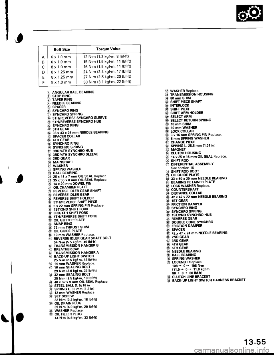
Bolt SizeTorque Value
cn
E
F
6x1.0mm
6x1.0mm
8 x 1.0 mm
8 x '1.25 mm
8 x 1.25 mm
8 x 1,0 mm
12 N.m (1.2 kgnm, 8 lbf'ft)
15 N.m (1.5 kgf'm, 11 lbf ft)
15 N.m (l.5 kgf.m, 11 lbift)
24 N'm (2.4 kgim, 17 lbift)
27 N.m (2.8 kgf.m,20 lbf'ft)
30 N.m (3.1 ksf m. 22 lbift)
5i WASHER Replace.6 TRANSMrssioN HouslNG!9 80 mm SHIM@ SHIFT PIECE SHAFT(6' INTERLOCK@ sHrFr PECE6} SHIFT ARM HOLDER@ seucr nnrvtI9 SELECT RETURN SPRING
@ 10 mm SHIM6, 10 mm WASHER@ LOCK COLLARi6sl 3 x l5 mm SPRING PIN Replace.t0 8 mm SPRING WASHERA) CHANGE PIECEll SPRING L.25.6 mm (1.01 in)'' MAGNET?4) CLUTCH HOUSINGta. 14 x 25 x 16 mm OIL SEAL Replace.A sHrFT BooO D|FFERENT|aL ASSEMBLYSee section 15iIO SHIFT ROD BOOT6 OIL GUIDE PLATE@ 33 x 60 x 20 mm NEEDLE BEASINGO BEARING RETAINER PLATElD LocK WASHER Replace..0 couNTERSHAFIA DISTANCE COLLAR6 & x 4I x 22 mm NEEDLE BEARING6. 1sr GEAR@ FRICTION DAMPERO SYNCHRO RING.d SYNCHRO SPRING@ 1ST/2ND SYNCHRO HUB..9i. REVERSE GEARC) DOUBLE CONE SYNCHROO FRICTION DAMPERS SPACER6 T2 x TI x 24 mm NEEDLE BEARING(!' 2ND GEAR61 3RD GEARiD 4TH GEAR@ 5TH GEAR(O NEEDLE BEARING(10 BALL BEARING@ SPRING WASHERf,o LoCKNUT Replace.108 - 0- 108 N'm111.0- 0* 11.0 kgf m,80* 0- 80lbI.ft)IO CLUTCH LINE BRACKET.d BACK.UP LTGHT SWITCH HARNESS BRACKET
:!, ANGULAR BALL BEABING:2, STOP RING:3] TAPER RING..-I NEEOLE BEARINGl!-- SPACERO SYNCHRO RING? SYNCHRO SPRINGE 5TH/REVERSE SYNCHRO SLEEVE...] sTH/REVERSE SYNCHRO HUB
O SYNCHBO EING.11-r sTH GEAR1A 38 x 43 x 26 mm NEEDLE BEARINGI13) SPACER COLLAR[!] /ITH GEAR.T5) SYNCHRO RING
O SYNCHRO SPRING17 3RD/4TH SYNCHRO HUB
O 3RD/4TH sYNcHRo SLEEVE
ii9 38D GEAR8I MAINSHAFT2i WASHERA SPRING WASH€R?I BALL BEARING.a4, 28 x 41 x 7 mm OIL SEAL Replace..2i 35 x 56 x 8 mm OIL SEAL Replace.t-t 14 x 20 mm DowEL PIN
.'] OIL CHAMBER PLATE
O REVERSE IDLER GEAR SHAFT.iI.., REVERSE IDLER GEAR'd REVERSE SHIFI HOLDERait srH/REVERSE sHIFT PIECE'34 5 x 22 mm SPRING PIN Replace.3' 1ST/2ND SHIFT FORK,34' 3RD/4TH SHIFT FORKi9t) srH/nevense sstrr ronx33 OIL GUTTER PLATE!' SNAP RING3d 72 mm THRUST SHIM
@ OIL GUIDE PLATE4t 10 mm WASHER Replaceti REVERSE TDLER GEAR SHAFT BoLT54 N.m {5.5 kgf m, 40lbIft)4N TBANSMISSION HANGER B43] BREATHER CAPA,J TRANSMISSION HANGER AIT' BACK-UP LIGHT SWITCH
I
25 N.m {2.5 kgl.m, 18lblftl14 mm WASHER RePlaceaO 14 mmtt 16 mm16 mm SEALING BOLT29 N.m (3.0 kgf m,22 lbf ft):4s) 32 mm SEALING BoLT25 N m 12.5 kgl m, 18 lbl'ft)40 x 62 x I mm OIL SEAL ReplaceSTEEL BALL D.5/15 iNSPRING L. 30 mm {1.2 in)12 mm WASHER Replace.SET SCREW22 N.m {2.2 kg{ m, 16 lbl ftlOIL DRAIN PLUG39 N.m {4.0 kgf m, 29lbtftlWASHER Replace.OIL FILLER PLUG4,t N.m {4.5 kgl m, 33 lblftl
.!rl00
@l
13-55
Page 647 of 2189
Mainshaft AssemblY
lndex
Note the follow
. The 3rd/4th and the 5th synchro hubs are installed with a press
. Install the angular ballbearing with the thin-edged cuter race facing the stop rrng'
Priorto reassembling. clean all the parts in solvent,drythem, and apply lu brica nt to any contact su rfaces The
3rd/4th and the sth synchro hubs, however, should be installed with a press before lubricating them'
ANGULAR BALL BEARING
Inspect lor wear
and operation.Note the drrectlonoI installatton.
v
SYNCHROSPRING
3RO/4TH SYNCHRO HUB
3RD GEARInspection,page 13-68,81
3RO/4TH SYNCHRO SLEEVE
SYNCHROSPRING
STOP RING
TAPER RING
NEEOLE EEARINGInspect for wearand operation.
SPACER
SYNCHRO RINGInspection.page 13-81
SYNCHROSPRING
SYNCHRO HUB
5TH/REVERSESYNCHRO SLE€VE
SYNCHEOSPRING
Inspection,page 13-81
NEEDLE BEARING
and operation.
SYNCHRO RINGInspection,page 13 8'1
GEARInspeclron,page 13-70,81
NEEDLE BEARINGInspect Ior wear
and operation.COLLAB
4TH GEARInspection,page 13'69,81
13-67
Page 670 of 2189

Mainshaft Thrust Clearance
Adjustment (cont'd)
13. Check the thrust clearance in the manner describedoetow.
CAUTION: Measuremenl should be made at roomtempetature.
a. Slide the mainshaft base over the mainshaft.
MAINSHAFT EASE07GAJ - PG20.130
b. Attach the mainshaft holder to the mainshaft asfollows:
NOTE:
. Back-out the mainshaft holder bolt and loosenthe two hex bolts.. Fit the holder over the mainshaft so its lip istowards the transmission.. AIign the mainshaft holder.s Iip around thegroove at the inside of the mainshaft splines,then tighten the hex bolts.
MAINSHAFT HOLOERBOLT
MAINSHAFT
[--F-e
l6fffi l
rx| - \-/ I/ Borrs
ff
MAINSHAFTHOLDER07GAJ - PG20110
MAINSHAFT BASE07GAJ - PG20130
13-90
c. Seat the mainshaft fully by tapping its end with aplastic hammer.
d. Thread the mainshaft holder bolt in untjl it justcontacts the wide surface of the mainshaft base.
e. Zero a dial gauge on the end ofthe mainshaft.
f. Turn the mainshaft holder bolt clockwise; stooturning when the dial gauge has reached itsmaxtmum movement. The reading on the dialgauge rs the amount of mainshaft end Dlav.
CAUTION: Turning tho mainshaft holder boltmore than 60 degrees after the needle of the dialg€uge stops moving may damage the transmis_ston.
07cAJ _ PG20110
g. lf the reading is within the standard, the clear-ance is correct.
lf the reading is not within the standard. recheckthe shim thickness.
Standard: 0.11 - O.18 mm {0.004 - 0.007 in}
DIAL GAUGE
Page 674 of 2189
Transmission
Reassembly (cont'dl
Install the dowel pins.
Install the transmission housing by aligning thegroove in the housing with the finger on the stopfl ng.
GROOVE
21.
Lower the transmission housing with the snap ringpliers, and set the snap ring in the groove of thecountershaft bearing.
TRANSMISSIONHOUSING
13-94
(
23. Check that the snap ring is securely seated in thegroove of the countershaft bearing.
Dimension 6) as instalt6d: 4.6 - 8.3 mm(0.181 - 0.327 inl
24.Install the clutch line bracket, transmission hangerA and back-up light switch ctamp, then tighten thetransmission housing attaching bolts in the num_bered sequence shown below.
ATTACHING BOLTS8 x 1.25 mmTRANSMISSIONHANGER A27 N m 12.8 kgtm, 20 tbt.trl
BACK.UP LIGHTSWITCH CLAMP
lar---'o o
"W