2000 HONDA CIVIC Top
[x] Cancel search: TopPage 217 of 2189
Piston Rings
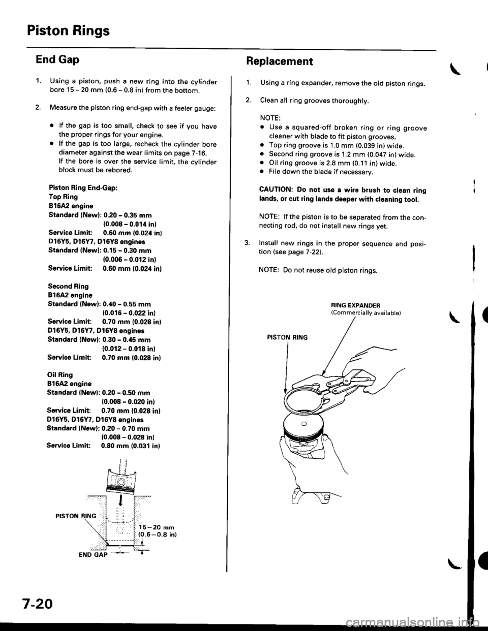
End Gap
1.Using a piston, push a new ring into the cylinderbore 15 - 20 mm (0.6 - 0.8 in) from the bottom.
Measure the piston ring end-gap with a feeler gauge:
. lf the gap is too small, check to see if you have
the proper rings for your engine.. lf the gap is too large. recheck the cylinder borediameter against the wear limits on page 7-16,
lf the bore is over the service limit, the cvlinderblock must be rebored.
Pkton Ring End-cap:
Top Ring
81642 engino
Siandtrd (New): 0.20 - 0.35 mm
{0.008 - 0.01,1 in)
Service Limit: 0.60 mm l0-02i1 inl
D16Y5. Dl6Y7, D16Y8 enginos
Standard lNewl: 0.15 - 0.30 mm
{0.006 - 0.012 in)
Ssrvic€ Limit 0.60 mm {0.024 inl
Socond Ring
816A2 ongina
Standard (Nowl: 0.40 - 0.55 mm
10.016 - 0.022 inl
Service Limit: 0.70 mm (0.028 inl
D16Y5, D16Y7, Dt6Y8 engines
Standard (New): 0.30 - 0.ia5 mm
{0.012 - 0.018 in)
Sorvice Limit 0.70 mm 10.028 inl
Oil Ring
81642 ongine
Standard {Now): 0.20 - 0.50 mm(0.008 - 0.020 inl
Sorvico Limit: 0.70 mm (0.028 in)
Dl6Y5. Dl6Y7, D16Y8 €nginos
Standard (Nowli 0.20 - 0.70 mm(0.008 - 0.028 inl
Servica Limit: 0.80 mm 10.031 in)
7-20
Replacement
1.Using a ring expander. remove the old piston rings.
Clean all ring grooves thoroughly.
NOTE:
. Use a squared-off broken ring or ring groove
cleaner with blade to fit piston grooves.
o Top ring groove is 1.0 mm (0.039 in)wide.. Second ring groove is 1.2 mm (0.047 in) wide.. Oil ring groove is 2,8 mm (0.11 in) wide.. File down the blade if necessary.
CAUTION: Do noi use a wire blush to clean ringlands. or cut ring lands deepol with cleaning tool.
NOTE: lfthe piston is to be separated from the con-necting rod, do not install new rings yet.
3. Install new rings in the proper sequence and posi-
taon (see page 7-22).
NOTE: Do not reuse old piston rings.
(Commercially available)
Page 218 of 2189
Ring-to-Groove Clearance
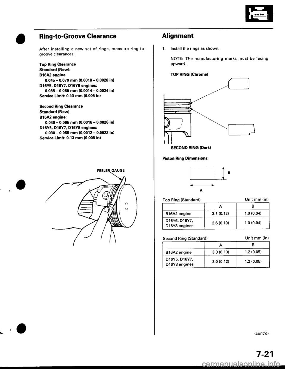
After installing a new set of rings, measure ring-to-
groove clearances:
Top Ring Clearance
Standard (New):
B16A2 angine:
0.045 - 0.070 mm (0.0018 - 0.(X128 in)
Dl6Y5, Dt6Y7, Dl6Y8 engin€s:
0.035 - 0.060 mm {0.0014 - 0.002'l in)
service Limit: 0.13 mm (o.fixi in)
Second Ring Clearance
Standard lNow):
B16A2 engine:
0.0/t0 - 0.065 mm (0.0016 - 0.0026 in)
Dl6Y5, D16Y7, D16Y8 onginos:
0.030 - 0.055 mm (0.(X)12 - 0.0022 in)
Sewica Limh: 0.13 mm (0.005 io)
.,o
Alignment
1. Installthe rings as shown.
NOTE: The manufacturing marks must be facing
upward.
SECOND RING (Darkl
Piston Ring Dimsnsions:
Unit mm (in)
Unit mm (in)
TOP RING (Chrome)
t----T f
lB
t---f_-L
A
Top Ring (Standard)
Second Ring (Standard)
B
Bl642 engine3.1 (0.12)1.0 (0.04)
D16Y5, D16Y7,
D16Y8 engines2.6 (0.10)1.0 (0.04)
B
816A2 engine3.3 (0.13)1.2 (0.05)
D16Y5, D16Y/.
D16Y8 engines3.0 (0.12)1.2 {0.05t
(cont'd)
7-21
Page 219 of 2189

Piston RingsCrankshaft Oil Seal
Alignment (cont'dl
TOP RING ---.>
SECOND RING >
MARK
,a-)
/\_4
o,.r^o( qffi<--sPACER
\Z-.
v
Rotate the rings in their grooves to make sure theydo not bind.
Position the ring end gaps as shown:
DO NOT position any ring gapat piston thrust surfaces.
DO NOT position any ring gapin line with the piston pin hole.OIL RING GAP
SECOND RING GAP
Approx.90
TOP RING GAP
7-22
Installation
The seal surface on the block should be dry.Apply a light coat of oil to the c.ankshaft and tothe lip of the seal.
1. Drive the crankshaft oil seal squarely into the right
side cover using the special tools.
HANDLE DRIVER07749 0010000
seal with thepan number sidefacing out.
Confirm that the clearance is equal all the way
around with a feeler gauge.
Clearance:0.5 - 0.8 mm (0.02 - 0.03 inl
NOTE: Refer to page 8-14 for installation of the oilpumo side crankshaft oil seal.
,(
\
Page 220 of 2189
PistonsGrankshaft
lnstallation
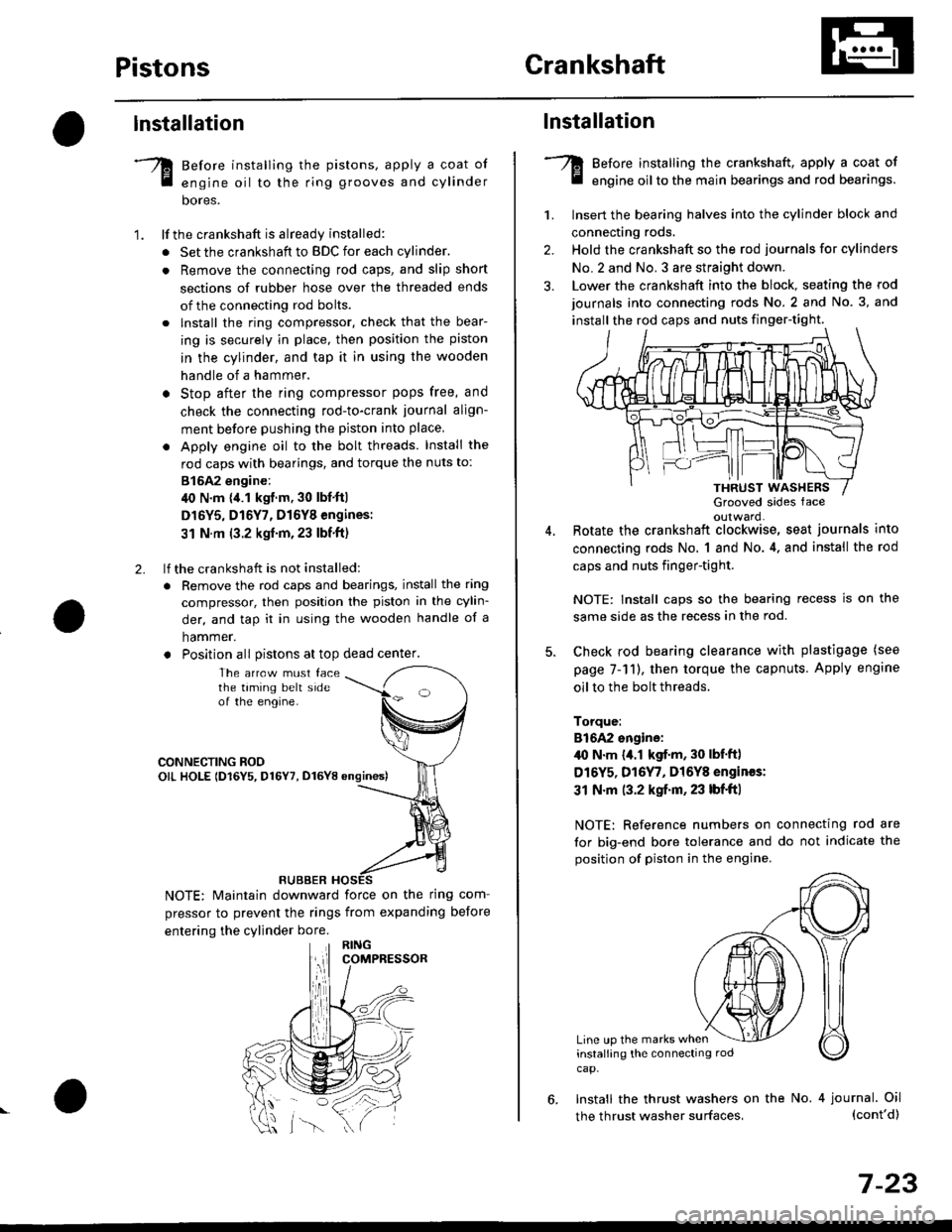
Before installing the pistons, apply a coat of
engine oil to the ring grooves and cylinder
bores.
lf the crankshaft is already installed:
. Set the crankshaft to BDC for each cylinder.
. Remove the connecting rod caps, and slip short
sections of rubber hose over the threaded ends
of the connecting rod bolts.
. lnstall the ring compressor. check that the bear-
ing is securely in place, then position the piston
in the cylinder, and tap it in using the wooden
handle of a hammer.
o Stop after the ring compressor pops free, and
check the connecting rod-to-crank journal align-
ment before pushing the piston into place
. Apply engine oil to the bolt threads. Install the
rod caps with bearings, and torque the nuts to:
815A2 engine:
40 N.m {,1.1 kgf.m, 30 lbf'ft|
D16Y5, D16Y7, D16Y8 engines:
31 N.m (3.2 kgf'm,23 lbf'ft)
lf the crankshaft is not installed:
. Remove the rod caps and bearings, install the ring
compressor, then position the piston in the cylin-
der, and tap it in using the wooden handle of a
hammer.
. Position all Distons at top dead center.
1.
2.
The arrcw must facethe taming belt sideof the engine.
CONNECTING ROOOIL HOLE lD16Y5, D16Y7, D16YB ongines)
NOTE: Maintain downward force on the ring com-
pressor to prevent the rings from expanding before
entering the cylinder bore.
RUBBER
,lll
lnstallation
Before installing the crankshaft, apply a coat of
engine oil to the main bearings and rod bearings.
Insert the bearing halves into the cylinder block and
connecting rods.
Hold the crankshaft so the rod journals for cylinders
No.2 and No. 3 are straight down.
Lower the crankshaft into the block, seating the rod
journals into connecting rods No. 2 and No. 3, and
install the rod caps and nuts finger-tight.
1.
2.
3.
5.
Grooved sides faceoulward.Botate the crankshaft clockwise, seat journals into
connecting rods No, 1 and No.4, and install the rod
caps and nuts finger-tight.
NOTE: Install caps so the bearing recess is on the
same side as the recess in the rod.
Check rod bearing clearance with plastigage (see
page 7-11), then torque the capnuts. Apply engine
oil to the bolt threads.
Torque:
816A2 sngine:/l{, N.m {a.l kgf.m, 30 lbf'ftl
D16Y5, D16Y7, Dl6Y8 engines:
31 N.m (3.2 kgf.m, 23 lbf'ft|
NOTE: Reference numbers on connecting rod are
for big-end bore tolerance and do not indicate the
position of piston in the engine.
Line up the marks wheninstalling the connectrng rod
cap.
6. Install the thrust washers on the No. 4 journal. Oil(cont'd)
7-23
the thrust washer surfaces,
Page 221 of 2189
Crankshaft
Installation (cont'd)
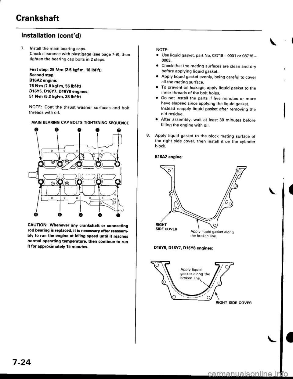
7. Installthe main bearing caps.
Check clearance with plastigage (see page 7-9), thentighten the bearing cap bolts in 2 steps.
First step: 25 N.m {2.5 kgf.m, 18 lbf.ft)
Second stop:
B1642 engine:
76 N.m {7.8 kgf.m, 56 lbf.ft)
D16Y5, D16Y7, D16Y8 engines:
51 N.m (5.2 kgf.m, 38 lbf.ft)
NOTE: Coat the thrust washer surfaces and boltthreads with oil.
MAIN BEARING CAP BOLTS TIGHTENING SEOUENCE
oocoo
CAUTION: Whenever any crankshaft or connectingrod bearing is replaced, it is necGssary after reassom-bly to run the engine at idling spe6d until it reachesnormal operating temperature, than continue to runit for approximately 15 minutos.
:V fr\-/.---\-/.-
7-24
NOTE:
. Use liquid gasket, part No. 08718 - 0001 or08718-0003.
. Check that the mating surfaces are clean and drybefore apptying liquid gasket.
. Apply liquid gasket evenly, being careful to coverall the mating surface.. To prevent oil leakage, apply liquid gasket to theinner threads of the bolt holes.. Do not install the parts if five minutes or morehave elapsed since applying the liquid gasket.
Instead reapply liquid gasket after removing theold residue.
. After assembly, wait at least 30 minutes beforefilling the engine with oil.
L Apply liquid gasket to the block mating surface ofthe right side cover, then install it on the cylinderblock.
Bl6A2 engine;
Apply tiquid gaslet alongthe broken line.
D16Y5, D16Y7, D16Y8 engines:
RIGHT SIDE COVER
Page 264 of 2189
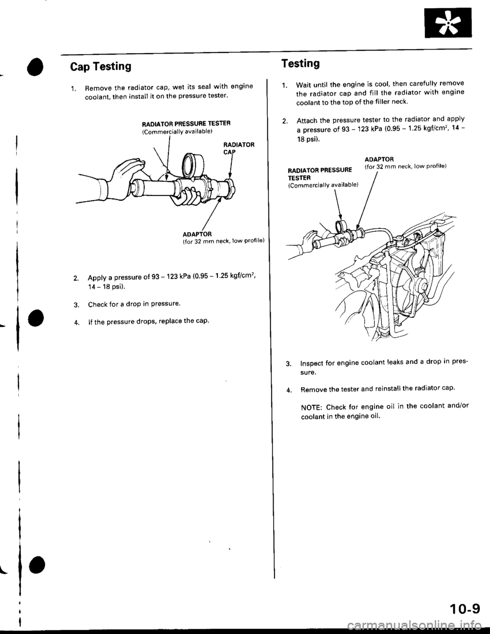
Cap Testing
1. Remove the radiator cap, wet its seal with engine
coolant, then install it on the pressure tester'
RADIATOR PR€SSURE TESTER(CommerciallY available)
RAOIATOR
(for 32 mm neck' low Pro{ile)
Apply a pressure of 93 - 123 kPa (0.95 - 'l 25 kgflcm'�'
14 - 18 psi).
Check for a drop in Pressure.
lf the pressure drops, replace the cap
I
t
ADAPTOR
Testing
LWait until the engine is cool, then carefully remove
the radiator cap and fill the radiator with engine
coolant to the top of the tiller neck
Attach the pressure tester to the radiator and apply
a pressure of 93 - '123 kPa (0.95 - 1.25 kgflcm'�, 14 -
18 psil.
RADIATOR PRESSURE
TESTER
lCommerciallY available)
ADAPTOR(for 32 mm neck, low Profile)
Inspect for engine coolant leaks and a drop In pres-
sure.
Remove the tester and reinstall the radiator cap
NOTE: Check for engine oil in the coolant and/or
coolant in the engine oil.
10-9
Page 272 of 2189
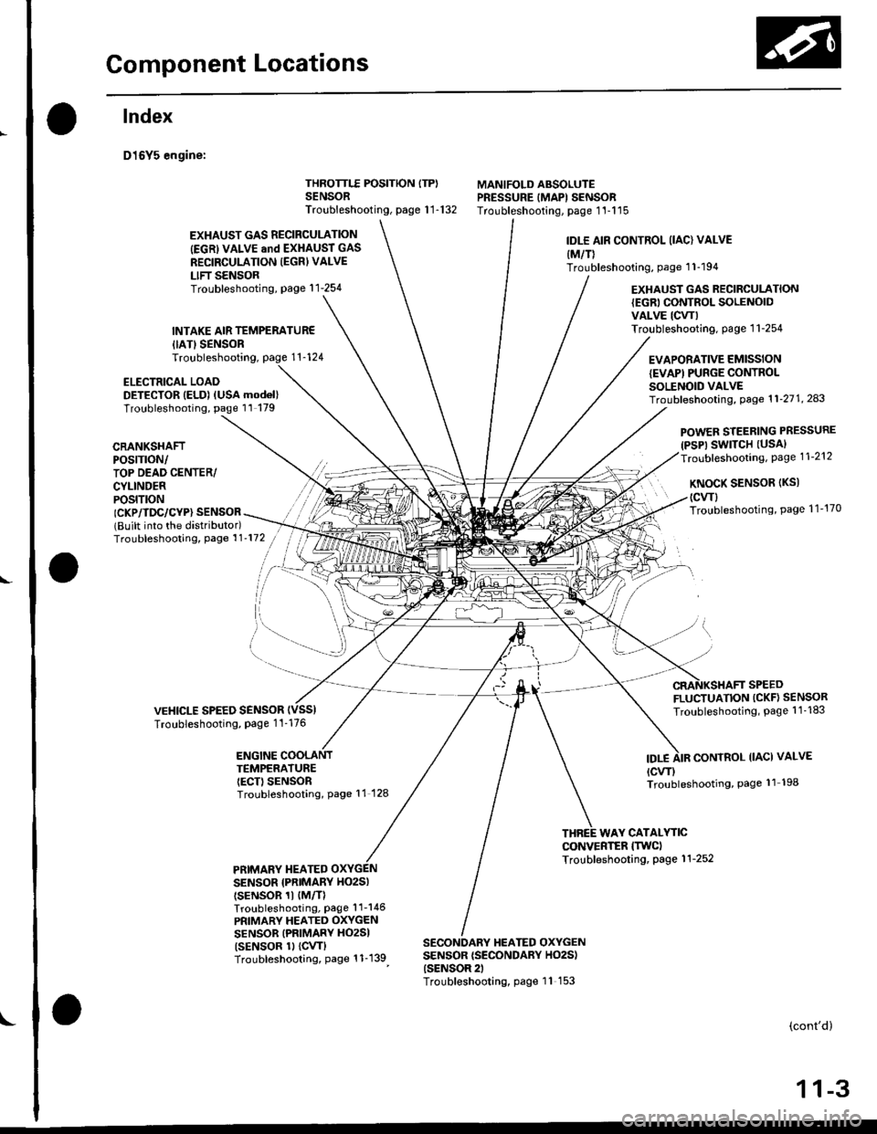
Gomponent Locations
L
lndex
D16Y5 engine:
{IATISENSORTroubleshooting,
ELECTRICAL LOADDETECTOR IELD) (USA mod6l)Troubleshooting, page 11 179
THROTTLE POSITION ITP)SENSORTroubleshooting, page 1 1-132
MANIFOLD ABSOLUTEPRESSURE IMAPI SENSORTroubleshooting, page 1'l-115
EXHAUST GAS RECIRCULATION
IEGRI VALVE and EXHAUST GAS
RECIRCULATION IEGRI VALVE
LIFT SENSORTroubleshooting, page'l 1-254
INTAKE AIR TEMPERATUR€
IDLE AIR CONTROL (IAC) VALVE
{M/T)Troubleshooting, page 1 1-194
EXHAUST GAS RECIRCULATION{EGRI CONTROL SOLENOIDVALVE ICW)Troubleshooting. page 1 1-254
EVAPORATIVE EMISSIONIEVAPI PUNGE CONTROLSOLENOID VALVETroubf eshooting, Page 1 1'21 1, 243
CRANKSHAFTPOS|TTON/TOP DEAD CENTER/CYLINDERPOS|T|ON
POWER STEERING PRESSURE(PSP) SWITCH (USAI
Troubleshooting, Page 1 1-212
KNoCK SENSoR (Ks)
(cwl
Troubleshooting, Page 1 1'170ICKP/TDC/CYP} SENSOR(Built into the distributor)Troubleshooting, Page 1 1'172
VEHICLE SPEED SENSORTroubleshooting, Page 1 1-176
FLUCTUATION (CKF} SENSOR
Troubleshooting, Page 1 1 -183
ENGINE COOLANTTEMPERATUREIECT) SENSORTroubleshooting, Page 11 128
IDT.ECONTROL IIACI VALVE
{cw)Troubleshooting, Page 11 198
WAY CATALYTICCONVERTER ITWCITroubleshooting, Page 1 1-252PRIMARY TIEATEDSENSOR {PNIMARY HO2SI
tsENsoR 1t {M/TlTroubleshooting, Page'l 1-146
PRIMARY HEATED OXYGENSENSOR (PRIMARY HO2SI
tsENsoR 1l {cw}Troubleshooting, Page 1 1-139
SECONDARY HEATED OXYGENSENSOR {SECONDARY HO2S){SENSOR 2)Troubleshooting, page 11 153
(cont'd)
1 1-3
Page 273 of 2189
Component Locations
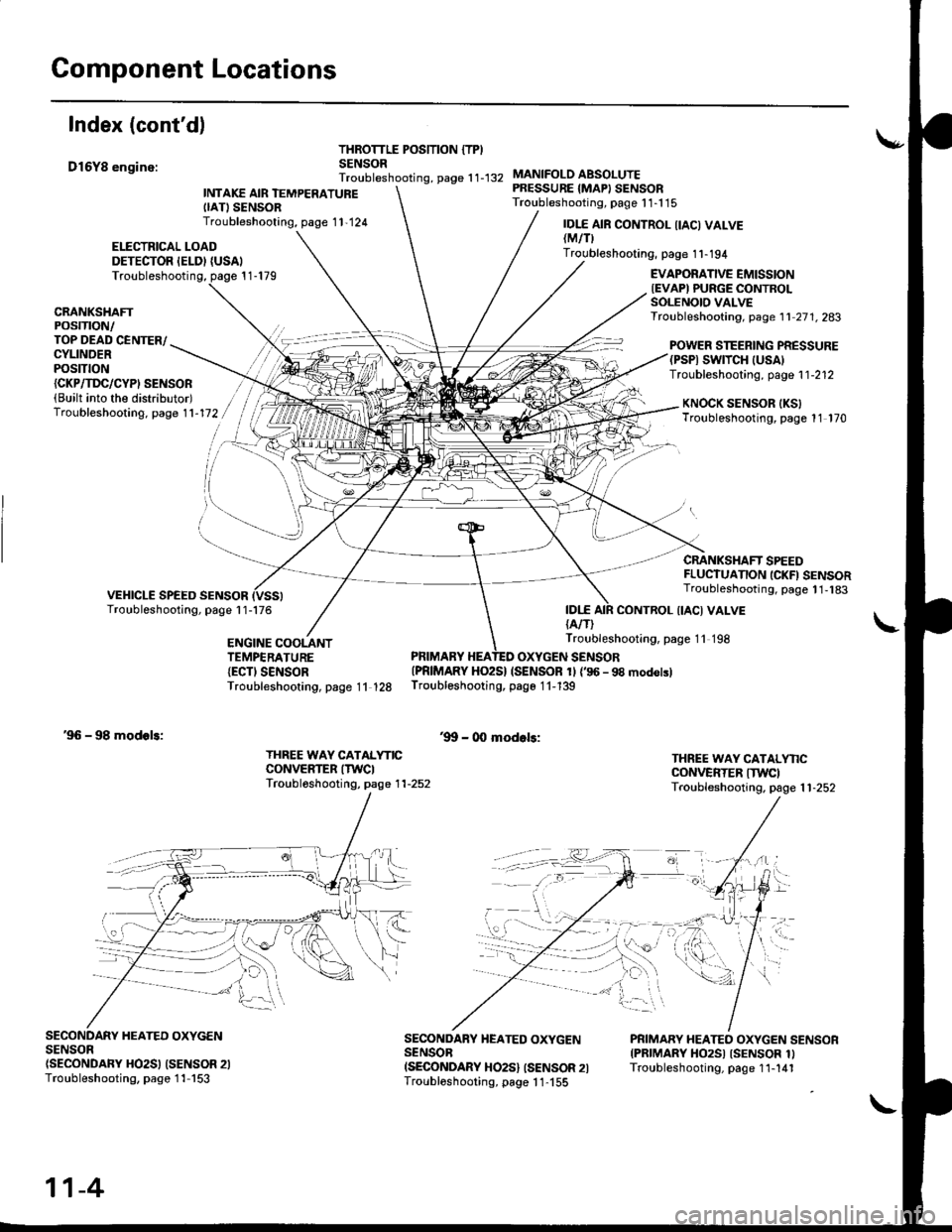
Index (cont'd)
D16Y8 enginc:
THROTTLE POSITION {TPISENSORTroubleshooting, page 1 1-132
ELECTRICAL LOADDETECTOR IELDI {USAI
INTAKE AIR TEMPERATUREIIATISENSORTroubleshooting, page 1 1,124
MANIFOLO ABSOLUTEPRESSURE {MAPI SENSORTroubleshooting, page 1 1-1 15
IDI.E{A/T)
IDI.E AIR CONTROL IIACI VALVElMtflTroubleshooting, page 1 1-194
Troubleshooting, page 1 1-179EVAPORATIVE EMISSIONIEVAPI PURGE CONTROLSOLENOIO VALVETroubleshooting, page 1 1 27 1. 283CRANKSHAFTPOSTTTON/TOP DEAD CENTER/CYLINDERPOStTtON
POWER STEERING PRESSURE(PSPI SWTTCH |USA)Troubleshooting, page 1 1-212{CKP/TI'C/CYPI SENSOR(Built into the distributor)Troubleshooting. page 1 1-172KNOCK SENSOR IKSITroubleshooting, page 11 170
CRANKSHAFT SPEEDFLUCTUANON ICKFI SENSORTroubleshooting, page 1 1,183
CONTROL {IACI VALVE
ENGINE COOLANTTEMPERATURE{ECTI SENSORTroubleshooting, page 11 128
Troubleshooting, page 11 198
PRIMARY HEATED OXYGEN SENSOR{PRIMARY HO2S} (SENSOR 1l {'96 - 98 modolslTroubleshooting, page 1 1-139
'9!t - 00 modols:'96 - 98 modols:
THREE WAY CATALYNCCONVERTER ITWCITroubl6shooting, page 1 1-252
THREE WAY CATALYNCCONVERTER ITWCITroubleshooting. page 1 1-252
SECONDARY HEATED OXYGENSENSOn(SECONDARY HO2SI (SENSOR 2ITroubleshooting, page 1 1-153
SECONDARY HEATED OXYGENSENSOBISECONDARY HO2S} ISENSOR 2ITroubloshooting, page 1 1-155
PRIMARY HEATEO OXYGEN SENSORIPRIMARY HO2SI ISENSOR 1ITroubleshooting, page 1 1-141
11-4