2000 HONDA CIVIC lock
[x] Cancel search: lockPage 1739 of 2189
)
Troubleshooting
Sef f -dia gnostic Proctdurcs ............. 2+13
Reading the DTC .............................. 2+13
Erasing the DTC Mcnrory ................ 24-15
Troubleshooting h.ttnitt.nt
Failures ..............24-15
SRS U n it ldcntificrtion .................... 24- 1 6
Diagnostic Troublc Code (DTC)
Chart - '96 - 97 Models..."'."....... 24-17
Diagnostic Trouble Code (DTCI
Chart - '$ - 00 Models '.........""' 24'19
SRS lndicaror Light Wire
connections ...'.,24-25
Ff owcharts ........,,,,.24-26
Airbag
Repfacemant ...'.'...24-67
Disposaf .................24'70
Cable Reel
Repfacement .........24'72
SRS Unh
Repfacement ..'......24'76
l-l
-+
sRs
Supplemental Restraint System (SRSI
Speciaf Tools ... ...........24'2
Component/Wirin g Locations
fndex ................ ......24-3
Description ................ 24-5
Circuit Diagram ......." 24'6
Precautions/Procedures
Generaf Precautions ...............,,,,,,,.. 24-7
Airbag Handling and Storage .........24-7
SRS Unit Precautions ...................... 24-8
Inspection After Deployment ........' 24-8
Wiring Precautions ................... ....... 24'9
Backprobing Spring-loaded Lock
Connectors .......,24-9
Spring-loaded Lock Connectol ....,,. 24-10
Spring-loaded Lock Connector with
Built-in Short Contact ................. 24-10
Disconnecting the Airbag
Connector(sl .....' 24'11
Steering-related Precautions ...,.,.,,. 24'12
Page 1747 of 2189
)
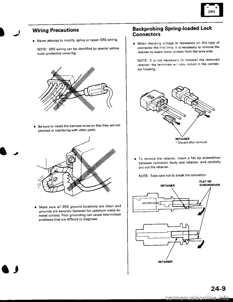
Wiring Precautions
. Never attempt to modify, splice or repair SRS wiring'
NOTE: SRS wiring can be identified by special yellow
outer Protective covering.
8e sure to install the harness wires so that they are not
oinched or interfering with other parts.
t
Make sure all SRS ground locations are clean and
grounds are securely fastened for optimum metal-to-
metal contact. Poor grounding can cause intermittent
problems that are difficult to diagnose.
a,
24-9
Backprobing Spring'loaded Lock
Gonnectors
. When checking voltage or resistance on this type of
connector the flrst time, it is necessary to remove lne
retainer to insert tester probes from the wire side.
NOTE: lt is not necessary to reinstall the removed
retainer; the terminals wi I stay locked in the connec-
tor housrng.
To remove the retainer, insert a flat tip screwdriver
between connector body and retainer, and carefully
pry out the retainer.
NOTE: Take care not to break the connector.
FLAT TIPSCBEWDRIVER
RETAINER* Discard after removal.
RETAINER
Page 1748 of 2189
Preca utions/Procedures
Spring-loaded Lock Connector
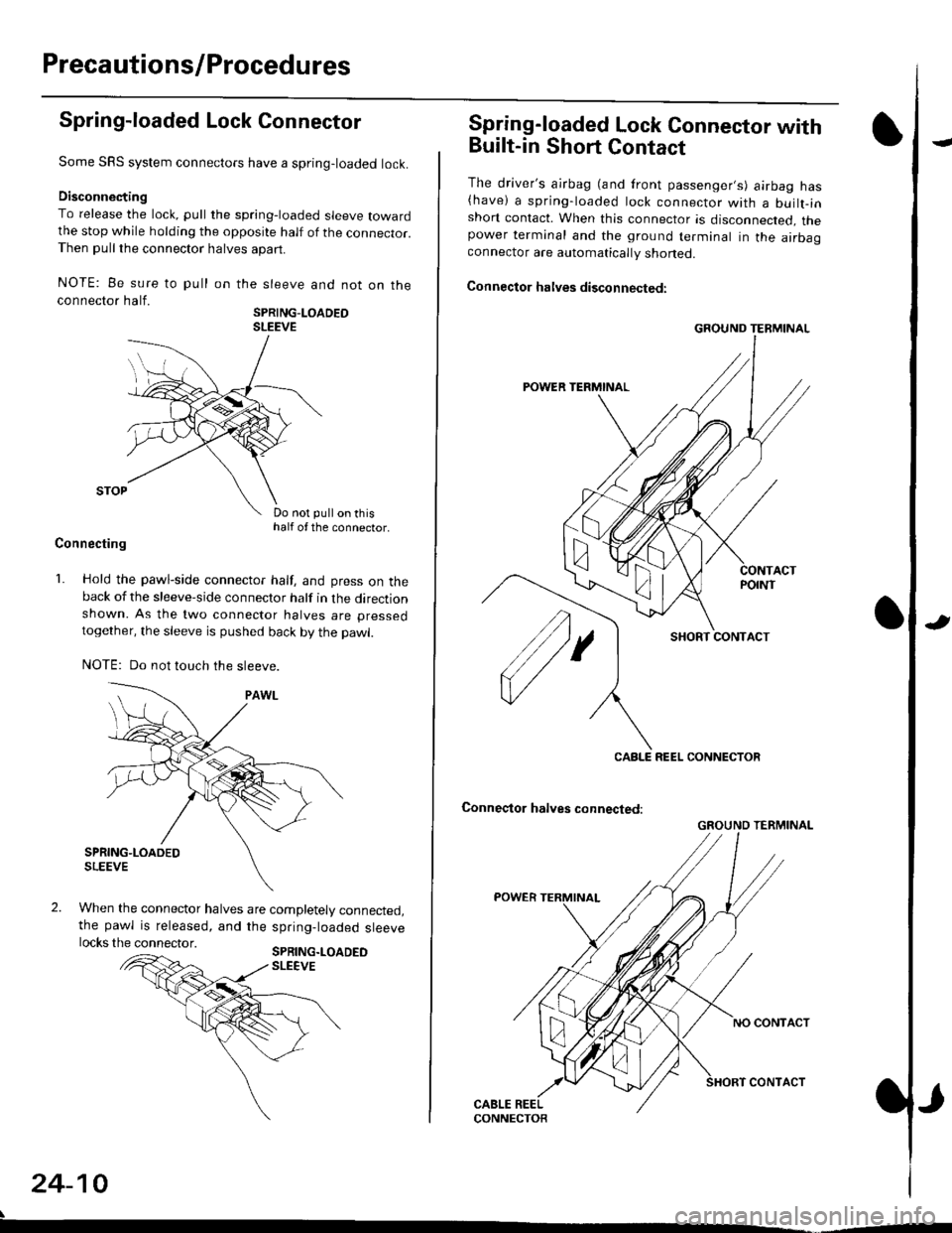
Some SRS system connectors have a spring-loaded lock.
Disconnecting
To release the lock, pull the spring-loaded sleeve towardthe stop while holding the opposite half of the connecror.Then pull the connector halves apart.
NOTE: Be sure to pull
connector half.
on the sleeve and not on the
SPRING-LOADEOSLEEVE
Do not pull on thishalf of the connector.
Connecting
1. Hold the pawl-side connector half, and press on theback of the sleeve-side connector half in the directionshown. As the two connector halves are pressed
together, the sleeve is pushed back by the pawl.
NOTE: Do not touch the sleeve.
When the connector halves are completely connected,the pawl is released, and the spring-loaded sleevelocks the connector.SPRING.LOADEDSLEEVE
24-10
Spring-loaded Lock Connector with
Built-in Short Contact
The driver's ajrbag (and front passenger,s) airbag has(have) a spring-loaded lock connector with a builr-inshort contact. When this connector is disconnected, thepower terminal and the ground terminal in the airbaaconnector are automatically shoned.
Connector halves disconnected:
SHORT CONTACT
Conneqtor halves connected:
GROUND TERMINAL
CABLE REEL CONNECTOR
GROUND TERMINAL
Page 1750 of 2189
Precautions/Procedu res
Steering-related Precautions
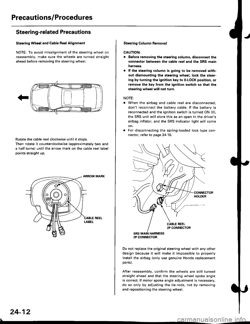
Stesring Wheel and Cable Reol Alignment
NOTE: To avoid misalignment of the steering wheel on
reassembly, make sure the wheels are turned straight
ahead before removing the steering wheel.
Rotate the cable reel clockwise until it stops.
Then rotate it counterclockwise {approximately two and
a half turns) until the arrow mark on the cable reel label
points straight up.
24-12
:l
St€€rin9 Column Removal
CAUTION:
. Eefore removing thg stggring column. disconnect the
connsstor bqtween the cable r€el and th€ SRS msin
harness.
. lf the stoering column is going to be romoved with-
out dismounting th6 stoering wheel, lock the steer-
ing by turning the ignition key to o-LOCK position, or
remove the key trom the ignition switch so that the
steering wheel will not turn.
NOTE:
When the airbag and cable reel are disconnected,
don't reconnect the battery cable. lf the battery is
reconnected and the ignition switch is turned ON (ll),
the SRS unit will store this as an open in the driver's
airbag inflator, and the SRS indicator light will come
on.
For disconnecting the spring-loaded lock type con-
nector, refer to page 24-'10.
SRS MAIN HARNESS2P CONNECTOR
Do not replace the original steering wheel with any other
design because it will make it impossible to properly
install the airbag (only use genuine Honda replacement
parts).
After reassembly, confirm the wheels are still turned
straight ahead and that the steering wheel spoke angle
is correct. lf minor spoke angle adjustment is necessary,
do so only by adjusting the tie-rods, not by removing
and repositioning the steering wheel.
Page 1751 of 2189
rl
Troubleshooting
t)
Self-diagnostic Procedures
The self-diagnostic function of the SRS system allows it to locate the causes of system problems and to store this informa' I
tion in memory. For easier troubleshooting, this data can be retrieved via a data link circuit l
. When you turn the ignition switch ON (ll), the SRS indicator will come on. ll it goes off after six seconds. the system is
norma l.
. lf there is an abnormality, the system locates and defines the problem, stores this information in memory, and turns
the sRS indicator light on. The data will remain in the memory even when the ignition switch is turned off or if the bat-
tery is disconnected.
o when you connect the scs service connector to the service check connector (2P), and turn the ignition switch oN (ll),
thesRsindicator|ightwi||indicatethediagnostictroub|ecode(DTC)bythenumberofb|inks.
. After reading and recording the DTC. proceed with the troubleshooting for this code'
Precauiions
.Useon|yadigita|mU|timetertocheckthesystem'|fit,snotaHondamu|timeter,makesureitsoutputisl0mA(0.01A)
or|esswhenSwitchedtothesma||estva|ueintheohmmeterrange,AtesterwithahigheroUtpUtcoulddamagethe��
airbag circuit or cause accidental airbag deployment and possible injury'
r when-ever the ignition switch is oN (ll). or has been turned oFF for lessthan three minutes, be careful nottobumpthe
SRS unit; the airbags could accidentally deploy and cause damage or injuries
. Before you ,"n1ou" th" SRS main harness, disconnect the driver's airbag connector (and the front passenger's airbag
connector).
. Make sure the battery is sufficiently charged {see section 23}. lf the battery is dead or low, measuring valLles won t be
correct.
. Do not touch a tester probe to the terminals in the sRS unit or harness connectors, and do not connect the terminals
with a jumper wire. Use only the backprobe set or the special tools'
For backprobing spring-loaded lock type connectors, refer to page 24-9'
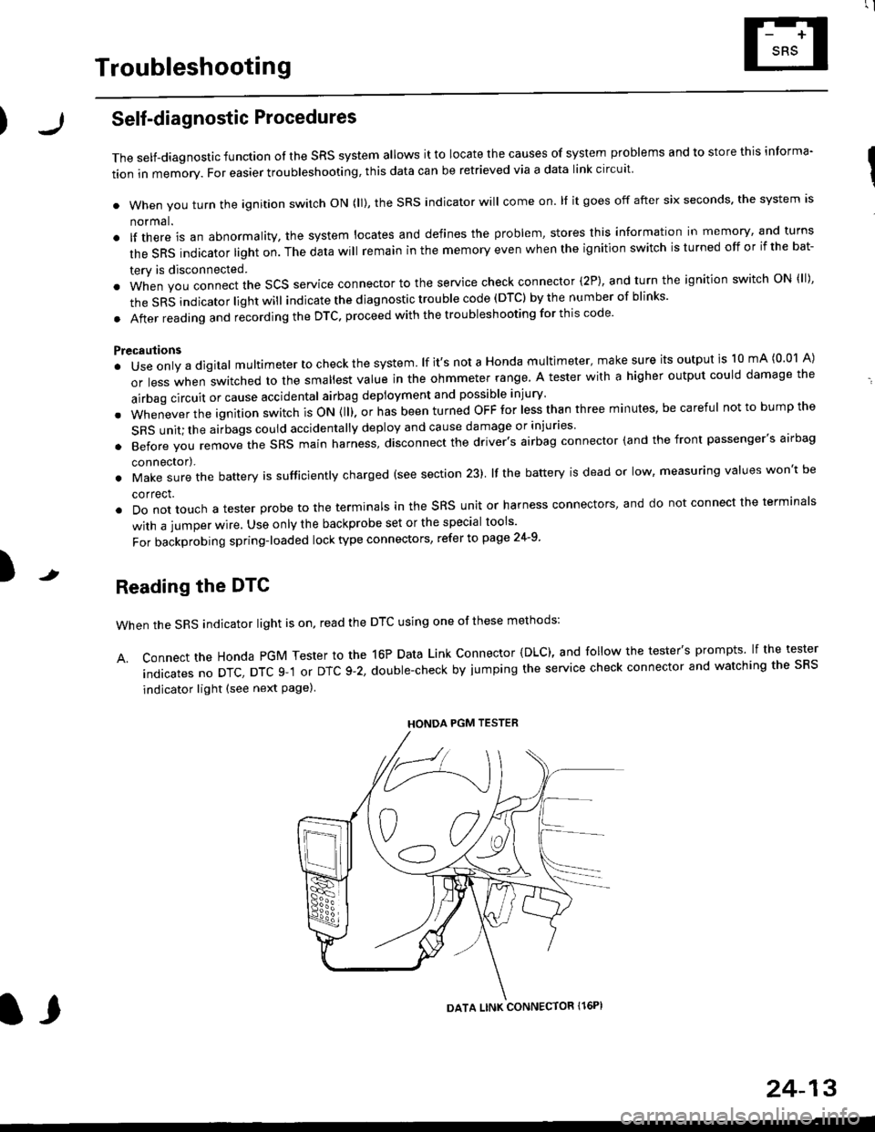
Reading the DTC
when the SRS indicator light is on, read the DTC using one of these methods:
A. Connect the Honda PGM Tester to the 16P Data Link Connector {DLC), and follow the tester's prompts lf the tester
indicatesnoDTc,DTcg-1orDTc9-2,doub|e-checkbyjumpingtheservicecheckconnectorandwatchingthesRS
indicator light (see next Page)
HONDA PGM TESTER
DATA LINK CONNECTOR Il6PI
l,
24-13
Page 1812 of 2189
Cable Reel
Replacement (cont'd)
11.
NOTE:
. Before installing the steering wheel, the front
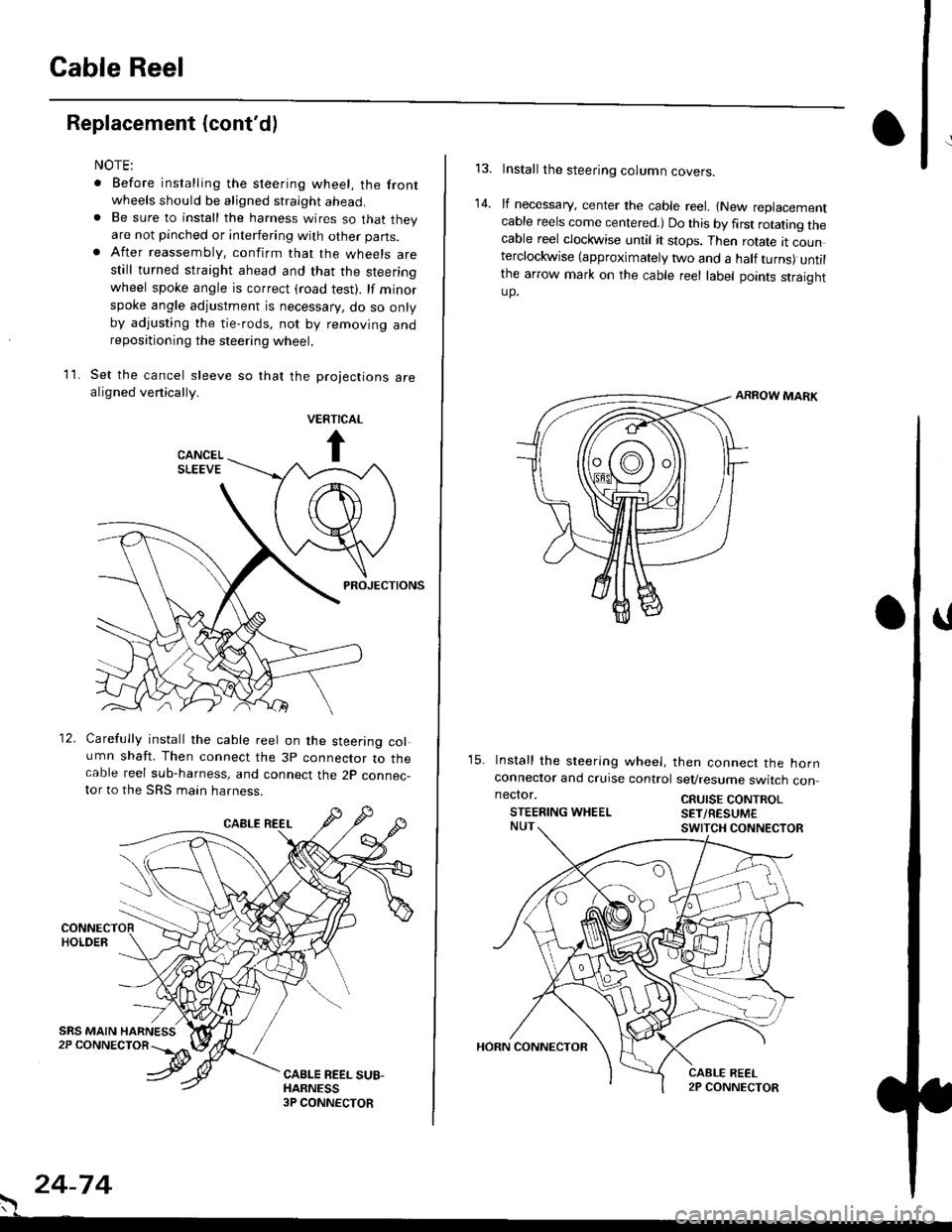
wheels should be aligned straight ahead.. Be sure to install the harness wires so that theyare not pinched or interfering with other parts.. After reassembly. confirm that the wheels arestill turned straight ahead and that the steeringwheel spoke angle is correct (road test). lf minor
spoke angle adjustment is necessary, do so onlyby adjusting the tie-rods, not by removing andrepositioning the steering wheel.
Set the cancel sleeve so that the projections arealigned venically.
PROJECTIONS
12. Carefully install the cable reel on the steering column shaft. Then connect the 3p connector to thecable reel sub-harness, and connect the 2p connec-tor to the SRS main harness.
. 24-74
Install the steering column covers.
lf necessary, center the cable reel. {New replacementcable reels come centered.) Do this by first rotating thecable reel clockwise until it stops. Then rotate tt counterclockwise (approximately two and a half turns) untilthe arrow mark on the cable reel label points straightup.
ARROW MARK
15. lnstall the sleering wheel, then connect the hornconneclor and cruise control sevresume switch con
14.
neclor.
STEERING WHEELCRUISE CONTROLSET/RESUM€
Page 1817 of 2189

Contents
How to Use This Manual ICircuit Schematics (see Circuit Index)Fuse/Relaylnformation 6Ground-to-Componentslndex 6-6ComponentLocationPhotooraohs 201Conriector Views 202
Circuit Index
Accessory power socket 155Air conditionerAir delivery'96198 models 61'99-'00 models 61-2Blower controls'96198 models 60'99100 models 60-1Compressor controls 62Fans 63Anti-lock brake system (ABS) 44A/T gear position indicatorCVT 89All except CVT 89-1Automatic transmission controlsAll '96-'98 models except CVT and GX 39All '99100 models except CVT 39-8All GX models 39-8'96-'�98 CVT 39-4'99100 cw 39-12Back-up lightsCoupe and Sedan 110Hatchback l'10-1Brake lightsAll Coupes and'96-'98 Sedans 110-15'99-'00 Sedans 110-16Hatchback 110-17Brake system indicator light'96198 models 7'1'99100 models 71-1Ceiling light 114-3Charging system 22Condenser fan 63Console lights 114Cruise control 34Dash lights 114Daytime running lights 110- 13Engine coolant temperature gauge 81-1Fog lights 110-10Front parking lights 110-2Fuel gauge 81-1Fuse/relay boxUnder-dash 6Under-hood 6-4Underhood ABS 6-3Gauges 81Ground distribution 14Ground-to-Componentslndex 6-6Hazard warning lightsAll except '99100 Sedans 110-6'99100 Sedans 110-8Headlights 110-12Headlight switch 100Heater - See Air ConditionerHorn'96197 models 40'98 model 40-1'99100 models 40-2lgnition key reminder 73lgnition systemAll '96198 models except Dl685 20All '99100 models except D16Y5 with Mn 2O-2All D1685 engines 20-2'99-'00 D 16Y5 with M/T 20
lndicators 80Integrated control unit 70lnterlock systemAll except'96J98 CVT 138'96198CVT 138-1License plate lightsAll Coupes and '96-'98 Sedans I l0-3'99100 Sedans 1 10-4Hatchback 110-5Low fuel indicator light 74Moonrool'96197 models |22'98-'00 models 122-1Odometer 81Oil pressure indicator light 80-3Power distributionBattery to ignition switch, fuses, and relaysFuses to relays and components 10-2Power door locksAll models without keyless entry 130'96-'98 models with keyless entry 130-2'99100 models with keyless entry 130-12Power mirrorsWithout detogger 141With defogger '141-2
Power windows 120Programmed fuel injection system (PGNr-Fl)All '96-98 models except D1685 23All '99-'00 models except D16Y5with M/T and D1685 24All D1685 engines 25'99100 D16Y5 with M/T 23Radiator fan 63Rear window defogger'96-,98 models 64'99100 models 64-1Seat belt reminder 73Security system'96.'98 USA HX, LX, EX 133'96-'98 Canada EX, Si 133'99TOO USA HX, LX, EX, DX.V Si 133-4'99100 Canada EX, Si 133-4All CX and DX models 133-8Speedometer 81Starting systemA./T (All except Dl685) 21A"/r (D16Bs) 21-1Manualtransmission 21-2Slereo sound system 150Supplemental rastraint system (SRS) 47Tachometer 81TailliqhtsAllboupes and'96-'98 Sedans 110-3'99100 Sedans 1 10-4Hatchback 110-5Trunk light 114-3Turn signal lightsAll except'99100 Sedans 110-6'99-'00 Sedans 1 10-8Vehicle speed sensor (VSS) 33Wiper/washerFront 91Rear 92
10
Page 1820 of 2189
Power Distribution Schematics
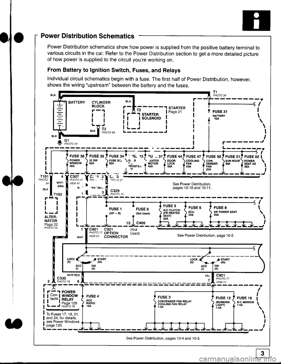
Power Distribution schematics show how power is supplied from the positive battery terminal to
various circuits in the car. Refer to the Power Distribution section to get a more detailed picture
of how power is supplied to the circuit you're working on.
From Battery to lgnition Switch, Fuses, and Relays
Individual circuit schematics begin with a fuse. The first half of Power Distribution, however,
shows the wiring "upstream" between the battery and the fuses.
CYLINDERBLOCK
tl
tlL.lt J
",-* f ]fo,o
i BATTERY
IIII
-
----------------Y-?-
ruse so I ruse as I ruse ga | ' ,s. ,a I =u. - srl ruse aai ruse qr I ruse so I ruse sr i ruse iapowEF csw FUsE Bc, \F,.n .;,cren ooon \coounc cor,r. \sun noor powrnw'NDowf50a {* .i1-;.*"1liT""fi3f* f5# fffi'*"f'* fS?'*
- - -L - - -. ... Ji - -.J.- - - -e- - -l. - - -La - J- - - I - - -
"";%,, Y rtr,' .9 l' -%,t",,vtEw47 I ! See Power Dastribution,w - vH-,alr. lt - pages 10,10and 10-11.
' I ---il 9,1?-l--4F--?-
i I
t.urr, 'rrr.,
t i!?'.,,?"" t::=. l ty::.1----.-
-
i
a I r(op-B) .{Noru3€d) J$ifl#ii Jtocl }3fo**."".o'
t -L - - -L - - -: rJ:e'- - -Ei s+s-r -.Fl-J-Jrr.-.
It-STARTER | !Pase 21 ! t FUSE 31I "rn*i
I f
*
i.Jr;-t
i L_i***'" iL-------J
ilr------!
FUSE /I4 ' FUSE 47 ' FUSE 5{' ' FUSE 51' FUSE 52
rlr
OOOB \COOLING CON. \SUN BOOF FOWER
t3f* f5# fffi*" f'* fs?'*
See Power Dastribution,pages 10'10 and 10-11.
T101
34
ALK
4
GAN
I
I
I
I
I\
\I
I
I
FUSE 8DF POWEF SEAT204
FUSE 6ECU204
FUSE 5A/C CLUICH(FN HEATEDSEAD204
C901 C921 {NotPHoro zz OPTION Used)v/EW22 CONNECTOBSee Power Distnbution, page 10-2.
1
FUSE 4
FADIO104
c901
vlEw22
FUSE 12(BUltNrrGLIGHT)
FUSE 19R/C MIRROF
YEL
7
i-f,r-- 't PowERI uon- I Wlt{DOWi racrs i RELAY. t P^da 1tL-J P;dr1ii-
FUSE 3CONOENSEF FAN RELAYCOOLING FAN RELAY
To Fuses 17, 18, 21,and 24, for details,see Power Windowspage 120.a
ll
ll
ALTER-NATORPage 22
f102
c330
See Power Distribution, pages 10-4 and 10-5.