Page 1931 of 2189
A/T Controls (All GX and All '99-'00 Models except CVI)
a
i-l-;;;
-rffi;----t
H*B'""i
! l r*-* i iflsln- :eepower ii|iii '
L_l____ _-i"utuiF#'i8 Y 93-s_1 SY C3s2 :""'".u I i,i?lol *"'o"n I iffl,1of
ll see eower ll wxrcnl - see power :
@
c131
vlEw 59
See GroundDistribulion,page 14-5. 1
["*
t*,t*;,,
;ffi i-
iilnirir,
Distribution,page 10-5.
,D5
, ry8 SOr)I Power source
BLI(YEL
il
10
WHT/BLU
821
(VBU)
Banery input
Servicecheck Vehicls Linear sol€noidconneclor speednput
' for solenoid valve ; \
Lock-up controlsolenoid valve (valve control circuitShift lock \
c'124
a
inpulinput
{8KSW)Brake switchInput
Shilt control solenoidvalve control
:::l
",:::[""::
. | .ir:Til**'
''lizll:l,,' i*'";l'-.----.'
O rr<( !!e"A65,
""il
SERVICE CHECKCONNECTOR
c12A
LTGRN/
I
SH IFTCONTROLSOLENOIDVALVES
LOCK.UPCONTROLSOLENOIDVALVESL__l+: G402a
il*-
except GX
See Powerr?F.| BRAKE SWTTCH
| | Closed with brake
| 1-I | !;€ja oeo'"""o
39-8
Page 1941 of 2189
Horn
- '99-'00 Models
FUSE 52HORI,SfOP LTt5a
UNDER.HOODFUSE/RELAYBOX
HORNRELAY
2
BIU/FED
Ior
GRY
.,1 ,
J---a-----r---O
i ;l i ;,1...,' r--1 : SECUR|TY:ll:sYsrEM,ia,coNNEcroR' ! ! (oPrloN), L--J , i!,o!o 73, KEYLESS I vlEw 58
: DooR LocK withi coNTRoL Kevless, UNIT EntryI PHOIO 134I vtEw 75
i o.--------;
:T:' cnvl :
i"l ii ri-'--.| coMBtNATtoN
: lrft ! !',f,11" I' | | puotozz :', l--J vttw u ;
i--- Er""pt ex.ooer ----j
c214
v|EW21
c430PHOTO 65
Vehicles pre-wired foraccessory security system
STEERINGWHEEL
CABLEREEL
.l
I
I
I
ISee CruiseControl
GRY
ELU
I
a\
I
GRY
HORN
---------^1
niffil"a!m"
40-2
Page 1942 of 2189
Anti-Lock Brake System (ABS)
UNDER.HOOD
H'.'"" ii[*:'*"
1
GFN
c357PHOTO 4
c359PHO|O 610
BEO
Grqlnd 2{GX!2)
l"l Fi* :l :l
!Ji I-J
.-L-----
i il
TPHOIO 125
44
Page 1944 of 2189

Anti-Lock Brake System (ABS) (cont'd)
(
FUSE 16iA DEFlEtsY See Power:ar Distribution,page 10-8.
c421 10
vlEW 50
'96- 97 Dl
mooels
.I UNDER-
page 1G6. I pHoro 5d
c501
vlEW 55
See Power Distribution,page 1S6.
AAS INDICATORLIG}IT
!'-r;us?;---l H5BE"
ilrryilrfi#ftilHriL-g------JL-g------J'tr F,1%'wHr/GRN I v/El.V 2Z
I t"r,o"" se€ Power
YELD5GAUGEASSEMBLY
usA
CarsdaI
(
D3
', ',i:,tr?""" ! P"g" t+-z".r',
*
! see cround Distributiofl,
".., I i"., I ".-l I;nl
iffit L------J
' n : G401
mI iot
T1*l ^*ry*l:-------l 8Bi"o.' used) ; 4ts5lnolcalor i UH|Tr----j. light conlrol r. iicib ett,"LTfflo",Input
1lo2)lgnition 2
Speed sensor anputsvlEw 63
(
{FLo) {FL1) (FBo) {FF1) (Rr"o) Sg____gT]-__g,l-j
Blo lf B23Y B8Y B21lf B6Y BlsY B4X B17f
i i I i o""l .,",-ul u.,"..1 o"",'.. I
rrttl
| | | I ,l ,l .I of"on"
ll ll I ti
't---'+----"[ --f !'?'%,'
""n*",lo"no""l *"1 *"*-l *"1 .'"."1 *,*.[ "**.I
I r L___t"" " t__t"." 1___!".""
"r.f_ "4::3' ;FJ,;::; ":f3:::1'' "lf-*i":''
t' ,.,Jtri"?r. ll;l]flffi lFli.ft. lU]flqtfl
l l"#tgl I lt5T8?l I lt"F"Ti?l I lt;Tt?f
O--t Distribution,
'n"r,o^n
I
Page 10-13'
.trr -N- .I BRAKE
| | swrrcH
igr:*
o"ntr"r
!
a'KBLU
It
""*[:-l
ftff^"n"o''''ot
I
", I
m;r""#,usi:",
".1
44-2
Page 1945 of 2189

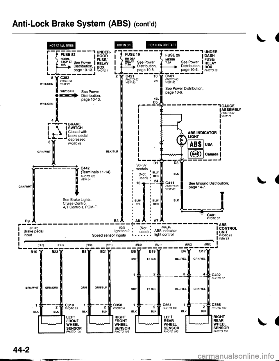
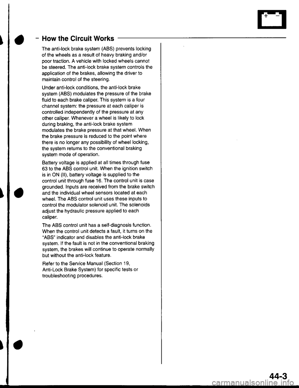
- How the Circuit Works
The anti-lock brake system (ABS) prevents locking
of the wheels as a result of heavy braking and/or
poor lraction. A vehicle with locked wheels cannot
be steered. The anti-lock brake system controls the
application of the brakes, allowing the driver to
maintain control of the steering.
Under anti-lock conditions, the antilock brake
system (ABS) modulates the pressure of the brake
tluid to each brake caliper. This system is a four
channel system: the pressure at each caliper is
controlled independently of the pressure al any
other caliper. Whenever a wheel is likely to lock
dunng braking, the anti-lock brake system
modulates the brake oressure at that wheel. When
the brake pressure is reduced to the point where
there is no longer any possibility of wheel locking,
the system returns to the conventional braking
system mode of operation.
Battery voltage is applied at all times through fuse
63 to the ABS control unit. When the ignition switch
is in ON (ll), battery voltage is supplied to the
control unit through fuse 16. The control unit is case
grounded. Inputs are received from the brake switch
and the individual wheel sensors located at each
wheel. The ABS control unit uses these inputs to
control the modulator solenoid unit. The solenoids
adjust the hydraulic pressure applied to each
calioer.
The ABS control unit has a self-diagnosis function.
When the control unit detects a fault, it turns on the"ABS" indicator and disables the anti-lock brake
system. lf the fault is not in the conventional braking
system, the brakes will continue to operate normally
but without the anti-lock feature.
Refer to the Service Manual (Section '19,
Anti-Lock Brake System) for specific tests or
troubleshooting procedures.
44-3
Page 1957 of 2189

- How the Circuit Works
Battery voltage is supplied through tuse 56 to the
A,/C compressor clutch r€lay contacts at all times.
With the ignition switch in ON (ll), vollage is applied
to the coil of the A,/C compressor clutch relay
through fuse 17. When you push the A,/C switch
ON, and the heater fan switch is in position | , 2, 3,
or 4, a "ground" input is provided to the engine
control module (ECM) or powertrain control module
(PCM) through the l'lC thermostat and the l'lC
pressure switch.
The A,/C compressor clutch relay is grounded by the
engine control module (ECM) or powertrain control
module (PCM). When energized, the A'lC
compressor clutch relay allows battery voltage to
turn on the A,/C comDressor clutch.
The A,/C ON indicator light comes on when the A,/C
system is requested.
A,/C Thermostat
The A'lC thermostat is located on the evaoorator
housing. The A,/C thermostat turns off the A,/C
compressor clutch if the temperature at the
evaporator goes below 3'C (37'F). This prevents
condensation from freezing on the evaporator fins
and blocking the air delivery into the passenger
compartment. The blower motor will keep running
when the sensor turns off the comDressor.
A,/C Pressure Switch
The fuC oressure switch is located in the condenser
outlet line where refrigerant is in a high
temperature/high pressure liquid state. The switch
will sense abnormally high or low pressure, and
open the circuit. This removes ground, and the
compressor will stop running.
Thermal Protectot
The thermal protector, located on the A,/C
compressor, opens and turns the compressor off if it
senses high temperature. Once the compressor
cools, the switch will close and the compressor will
begin running again.
Refer to the Service Manual (Section 22,
Air Conditioning) for specific tests or
troubleshooting procedures.
62-3
Page 1961 of 2189

- How the Circuit Works
Radiator Fan
Voltage is provided at all times to the radiator fan
relay (contacts) through fuse 57. With the ignition
swilch in ON (ll), voltage is provided to the coil of
the relay through luse 17.
The radiator tan relay can be grounded through
either the engine coolant temperature switch or the
engine control module (ECM) or powertrain control
module (PCM).
The engine coolant temperature switch grounds
the radiator fan relay (coil) when the engine
coolant temperature exceeds 199'F (83'C). The
switch opens when coolanl temperature
decreases 3'- 8'C.
Condenser Fan
Voltage is provided at all times to the condenser fan
relay (contacts) through fuse 56. With the ignition
switch in ON (ll), voltage is provided to the coil of
the relay through fuse 17. When you push the A'lC
switch and put the heater fan switch in 1, 2,3, o( 4
position, the ly'C thermostat comes on, the
condenser fan relay energizes, and the condenser
fan motor runs.
A,/C Thermostat
The A,/C thermostat is located on the evaporator
housing. The A,/C thermostat tums off the A/C
compressor clutch if the temperature at the
evaporator goes below 3'C (37'F). This prevents
condensation from freezing on the evaporator fins
and blocking the air delivery into the passenger
compartment. lf the temperature goes below 3'C
(37"F) tuming off the Ay'C thermostat, ground will be
removed from the condenser fan relay. This will
deenergize the relay and remove voltage from the
condenser fan motor causing the fan to stop running.
Reter to the Service Manual (Section 23, Eleckical)
for specific tests or troubleshooting procedures.
63-3
Page 1981 of 2189
A/T Gear Position Indicator
{\
-cw
@UNDER-DASHFUSE/RELAYBOX
r
See A/TControls
"Ttr
See Dash andConsole Lights
-AYlltFED I FED/BLK I
tl
YEL
A1
SEE A,TTControls,PGM.FI
I
;l
A/T GcarPoiltlo{|Indlc{or
GAUGEASSEMBLY
a\
t----Y---
BLKBLU
12
GRNA!/HT
c410
vtEw 35
BLKaLu
I
See A,/TControls
TI
:I
a
ta
A.t 3
BLKBLU
7
BLK/BLU
eui [SBruI
SeelnterlockSystem
I
;+
ar
l
-;-----;++
-l-rl
c433
A/TGEARPOStTtONswrTcH
Sec GroundDistribution,pag€ 1+7.
Y
I
I
aL__l+: G401
\
89