Page 1801 of 2189
,)
IJ
t,
From page 24'62 (A)
Check the cable reel:
1. Turn the ignition switch OFF
2. Disconneit the cable reel 2P connector from the SRS
maln harness,
3. Turn the ignition switch ON {ll}
4. Connect a voltmeter and measure voltage between the
No. 1 terminal of the SRS main harness 18P connector
and ground, and between the No 13 terminal and
ground. There should be approx. 0 - 0.5 V'
Are vohtg6 as specifi"dT -
YESNO
Short to powor in the cabto reel; replace thg cable rool
(see page 24'721.
Short to powet in the SRS main h.rness; replace the SRS
main harness.
24-63
Page 1802 of 2189

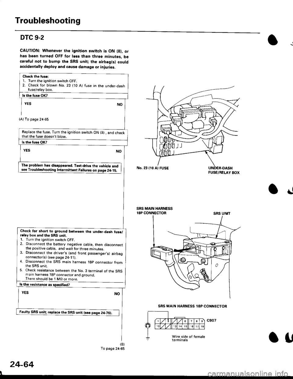
Troubleshooting
DTC 9-2
CAUTION: Whenever the ignition switch is ON 0l), ofhas been turned OFF lor lass than three minutes, becareful not to bump the SRS unit; the airbag(s) couldaccidentally deploy lnd caqse damage or iniuries.
Check the tu.c:1. Turn the ignition switch OFF.2. Check for blown No. 23 (10 A) fuse in the under,dashfuse/relay box.
Replace the tuse. Turn the ignition switch ON lll) , and checkthat the fuse doesn't blow.
Th6 problem hs3 disappe.rod, TGt-dJiv€ the vehiclo and3ee Troublerhooting Intermiftcnt Failuro3 on paqo 2l-15.
Check tol short to ground betwe.n tho unde.-da3h fus./r.ley box and the SRS unit.1. Turn the ignition switch OFF.2. Disconnect the baftery negative cable, then disconnectthe positive cable, and waittorthree minutes.3. Disconnect the driver's (and front passenger,s) airbagconnector(s) (see page 24-11).4. Disconnect the SRS main harness 1gp connector fromthe sRs unit.5. Check resistance between the No. 3 terminal of the SRSmarn harness 18P connector and ground,There should be 1 MO or more.
Feufty SRS unh; rcphce the SRS unit lsee pag.2+761.
(A)To page 24-65
To page 24-65
No. 23 lr0 Al FUSEFUSE/RELAY BOX
!
SRS MAIN HARNESS18P CONNECTORSRS UN'T
24-64
I
SRS MAIN HARNESS 18P CONNECTOR
Otf
Page 1803 of 2189

)
FUSE/BELAY BOX
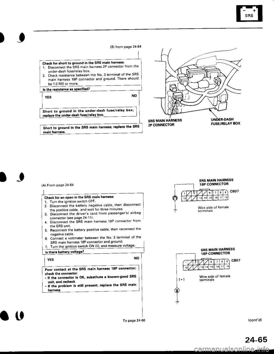
Chcck for an op€n in th6 SRS main harness:
1. Turn the ignition switch OFF.
2. Disconne;t the battery negative cable, then disconnect
the positive cable, and wait for three minutes'
3. Disconnect tho driver's (and front passenger's) airbag
connector (see Page 24'11).
4. Disconnect the SRS main harness 18P connector from
the SRS unit
5. Reconnect the battery positive cable, then reconnect the
neoative cable.
6. Co-nnect a voltmeter betlveen the No 3 terminal ol the
SFS main harness 18P connector and ground'
7. Turn theswitch ON (ll), and m€asure
(cont'd)
(B) from page 24-64
Check tor ahort to ground in the SRS main harn$s:
1. Disconnect the SRS main harness 2P connector from the
under-dash fuse/relaY box.
2. Check resistance between the No. 3 terminal of the SRS
main harness 18P connector and ground There should
be 1.0 M0 or more.
ls the re3istance a3 specified? -
NOYES
Short to giound in tho undot-drlh lut'/rol'y box;
replace the undel-da3h fusgtgEl!9l--------.-
Short to ground in tho SRS m.in harn$s; ropleco the SRS
main harness.
(AlFrom page 24'64
Poor contact at the SRS main harnoss 18P connoctor;
check lho connoctor.. ll the connector k OK, sub3titute r known'good SRS
unh. and recheck. lf the problom is slill present, lepl.ce the SRS main
To page 24-66
SRS MAIN HARNESS18P CONNECTOR
o0
24-65
Page 1804 of 2189
Troubleshooting
DTC 9-2 (cont'dl
2- Disconnect the SRS rnain harness 2p connector lrom theunder-dash fuse/relay box.3- Check resistance between the No. 2 terminal of the SRSmain harness 2P connecior and No. 3 terminal of theSFS main harness 18P connector_
Poor contact at the SRS main ha.ness 2p connector;check the connecto... lf the connector is Ol(, sub3titute a known-good under-dash tuse/r€lay box, and recheck.'lt tho problem is still present, replece the SRS main
Open in the SBS main harness; replace the SRS main har_ness,
SRS MAIN HARNESS2P CONNECTOR
24-66
I
\
From page 24-65
Chock tor an open in th€ SRS main hern€ss:1. Turn the ignition switch OFF.
There should be 0 0.5 0
SRS MAIN
SRS MAIN HARNESS18P CONNECTOR
o!
Page 1807 of 2189
)
5, Reconnect the airbag connector(s)'
Front Passengor's Side:
a Attach the airbag connector to the connector holder'
then reinstallthe glove box.
FRONT PASSENGER'S AIRBAG
oo
24-69
Driver's Side:
a Connect the driver's airbag 2P connector to the cable
reel 2P connector, then install the acc€ss panel on the
steering wheel
DRIVER'S AIRBAG2P CONNECTOR
6. Connect the battery positive cable, then connect the
negative cable.
7. After installing the
operatlon:
. Turn the ignition
tor light should
and then go off
a Make sure both horn buttons work
airbag, confirm Proper sYstem
switch ON (ll); the SRS indica-
come on for about six seconds
Page 1813 of 2189

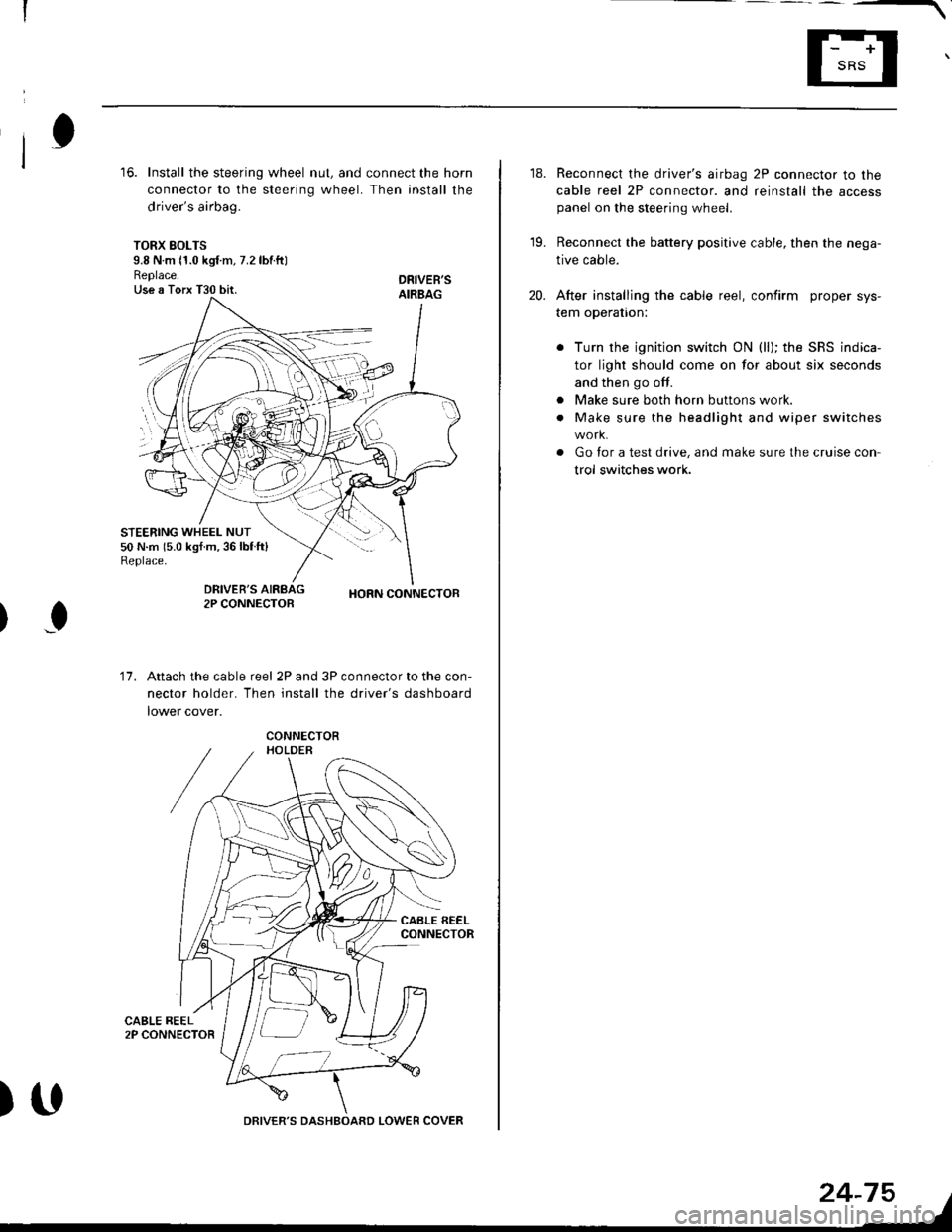
16. Install the steering wheel nut, and connect the horn
connector to the steering wheel. Then install the
driver's airbag.
TORX SOLTS9.8 N m 11.0 kgf m, 7.2 lbtftlReplace.Use a Torx T30 bit.
STEERING WHEEL NUT50 N.m 15.0 kgf.m,36lblft)Replace.
DRIVEB'SAIRBAG
DRIVER'S2P CONNECTOBHORN CONNECTOB
I
17.Attach the cable reel 2P and 3P connector to the con-
nector holder. Then install the driver's dashboard
lower cover.
)UDRIVER'S DASHBOARD LOWER COVER
24-75
18. Reconnect the driver's airbag 2P connector to the
cable reel 2P connector. and reinstall the accesspanel on the steering wheel.
19. Reconnect the battery positive cable, then the nega-
tive cable.
20. After installing the cable reel, confirm proper sys-
tem operation:
Turn the ignition switch ON (ll); the SRS indica-
tor light should come on for about six seconds
and then go off.
Make sure both horn buttons work.
Make sure the headlight and wiper switches
Go for a test drive, and make sure the cruise con
trol switches work.
a
a
Page 1815 of 2189
6. Install the new SRS unit.
NOTE: Do not reuse a torx bolt that has red
threads. Replace the bolt with a new one.
)
7.
TORX BOLTS9.8 N.m l'1.0 kg{.m, 7.2 lbf.ft}Use a Torx T30 bit.
Connect the SRS main harness l8P connector to the
SRS uniu push it into posjtion until it clicks.
Install the SRS unit covers (ri9ht and left). Make
sure the covers snap together in the middle.
8.
TORX BOLTS9.8 N.m 11.0 kgf.m, 7.2 lbf.ft)U3e . Torx T30 bit.
SRS MAIN HARNESS
)(l
9.
10.
't2.
Reconnect the driver's aibag 2P connector to the
cable reel 2P connector, then reinstall the access
panel on the steering wheel.
Reconnect the tront passenger's airbag connector
to the SRS main harness.
Reconnect the battery positive cable, then the nega
tive cable.
After installing the SRS unit, confirm proper system
operation: Turn the ignition switch ON (ll); the SRS
indicator light should come on for about six seconds
and then go oif.
11.
24-77
.-
Page 1817 of 2189

Contents
How to Use This Manual ICircuit Schematics (see Circuit Index)Fuse/Relaylnformation 6Ground-to-Componentslndex 6-6ComponentLocationPhotooraohs 201Conriector Views 202
Circuit Index
Accessory power socket 155Air conditionerAir delivery'96198 models 61'99-'00 models 61-2Blower controls'96198 models 60'99100 models 60-1Compressor controls 62Fans 63Anti-lock brake system (ABS) 44A/T gear position indicatorCVT 89All except CVT 89-1Automatic transmission controlsAll '96-'98 models except CVT and GX 39All '99100 models except CVT 39-8All GX models 39-8'96-'�98 CVT 39-4'99100 cw 39-12Back-up lightsCoupe and Sedan 110Hatchback l'10-1Brake lightsAll Coupes and'96-'98 Sedans 110-15'99-'00 Sedans 110-16Hatchback 110-17Brake system indicator light'96198 models 7'1'99100 models 71-1Ceiling light 114-3Charging system 22Condenser fan 63Console lights 114Cruise control 34Dash lights 114Daytime running lights 110- 13Engine coolant temperature gauge 81-1Fog lights 110-10Front parking lights 110-2Fuel gauge 81-1Fuse/relay boxUnder-dash 6Under-hood 6-4Underhood ABS 6-3Gauges 81Ground distribution 14Ground-to-Componentslndex 6-6Hazard warning lightsAll except '99100 Sedans 110-6'99100 Sedans 110-8Headlights 110-12Headlight switch 100Heater - See Air ConditionerHorn'96197 models 40'98 model 40-1'99100 models 40-2lgnition key reminder 73lgnition systemAll '96198 models except Dl685 20All '99100 models except D16Y5 with Mn 2O-2All D1685 engines 20-2'99-'00 D 16Y5 with M/T 20
lndicators 80Integrated control unit 70lnterlock systemAll except'96J98 CVT 138'96198CVT 138-1License plate lightsAll Coupes and '96-'98 Sedans I l0-3'99100 Sedans 1 10-4Hatchback 110-5Low fuel indicator light 74Moonrool'96197 models |22'98-'00 models 122-1Odometer 81Oil pressure indicator light 80-3Power distributionBattery to ignition switch, fuses, and relaysFuses to relays and components 10-2Power door locksAll models without keyless entry 130'96-'98 models with keyless entry 130-2'99100 models with keyless entry 130-12Power mirrorsWithout detogger 141With defogger '141-2
Power windows 120Programmed fuel injection system (PGNr-Fl)All '96-98 models except D1685 23All '99-'00 models except D16Y5with M/T and D1685 24All D1685 engines 25'99100 D16Y5 with M/T 23Radiator fan 63Rear window defogger'96-,98 models 64'99100 models 64-1Seat belt reminder 73Security system'96.'98 USA HX, LX, EX 133'96-'98 Canada EX, Si 133'99TOO USA HX, LX, EX, DX.V Si 133-4'99100 Canada EX, Si 133-4All CX and DX models 133-8Speedometer 81Starting systemA./T (All except Dl685) 21A"/r (D16Bs) 21-1Manualtransmission 21-2Slereo sound system 150Supplemental rastraint system (SRS) 47Tachometer 81TailliqhtsAllboupes and'96-'98 Sedans 110-3'99100 Sedans 1 10-4Hatchback 110-5Trunk light 114-3Turn signal lightsAll except'99100 Sedans 110-6'99-'00 Sedans 1 10-8Vehicle speed sensor (VSS) 33Wiper/washerFront 91Rear 92
10