2000 HONDA CIVIC light
[x] Cancel search: lightPage 1796 of 2189
Troubleshooting
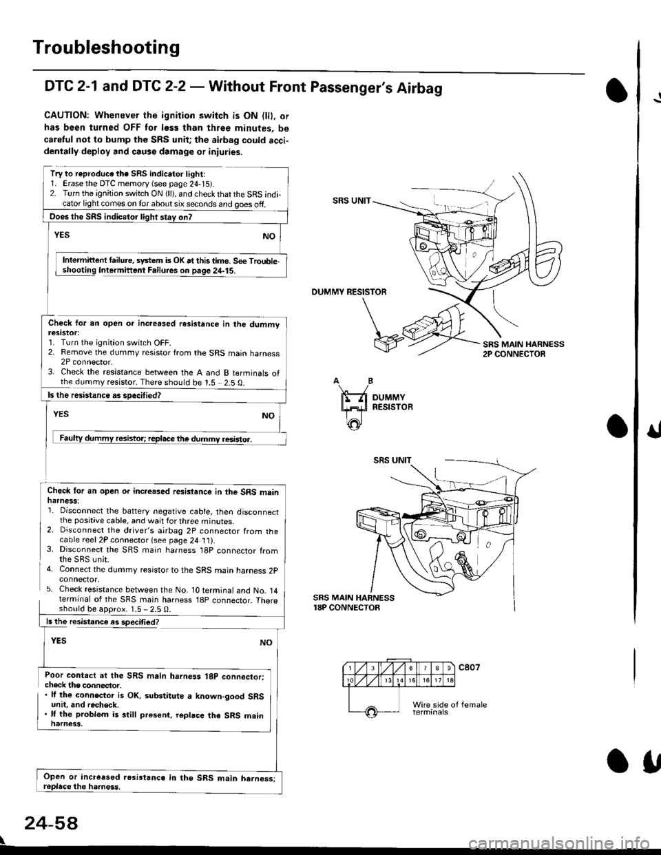
DTC 2-1 and DTC 2-2 - Wathout Front Passenger's Airbag
CAUTION: Whenever the ignition switch is ON {lll. or
has been turned OFF tor less than three minutes, be
caretul not to bump the SRS unit; the aidag could acci-dentally deploy and causs damage or iniuries.
Try to reproduc€ the SRS indicator light:1. Erase the DTC memory {see page 24-15r.2. Turn the ignition switch ON (ll), and check thatthe SRS indicator light comes on lor about six seconds and ooes off.SRS UNIT
Intermittent failu.e, system is OK at this time. Se€ Trouble-Intermifient Failuies on paqe 24-15.
OUMMY RESISTOR
Check for an open oa increased resistance in the dummvteslstot:1. Turn the ignition switch OFF.2. Remove the dummy resistor from the SRS main harness2P connector,3. Check the resistance between the A and B terminals ofthe dummy resistor. There should be 1.5 - 2.5 0.
resistoa.
Check lor an open or incre.sed resisiance in the SRS mainharness:'1. Disconnect the battery negative cable, then disconnectthe positive cable, and wait for three minutes.2. Disconnect the driver's airbag 2P connector from thecable reel2P connector lsee page 24 t t).3. Disconnect the SRS main harness t8p connector fromthe SBS unit.4. Connect the dummy resistor to the SRS main harness 2pconnector.5. Check resistance between the No- 1O terminal and No. 14terminal of the SRS main harness 18p connector. Thereshould be aDorox. 1.5 - 2.5 0.
SRS MAIN HARNESS18P CONNECTOR
ls the resistance es speciti€d?
YES
Poor contact ar the SRS main hahess 18p connector;check the connector.. lf the connector is OK. substitute a known-good SRSunit, and recheck.. lf the problem is still present. repbce the SRS mainnarness.
24-5A
\
Ooes the SRS indicalor light stay on?
Open or increased resi3tanc6 in tho SRS main harness;OU
I
Page 1797 of 2189
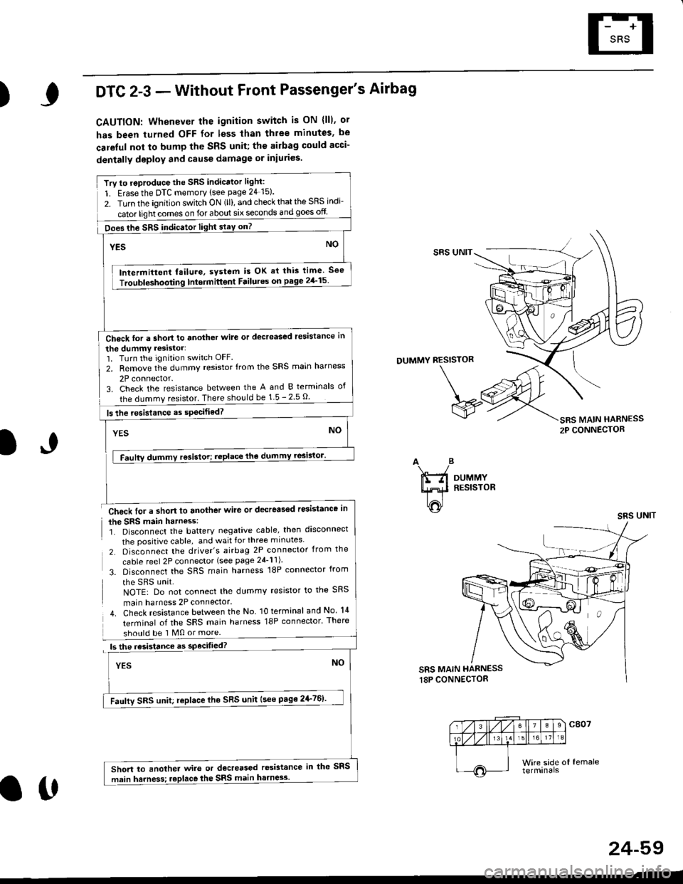
)DTC 2-3 - Without Front Passenger's Airbag
CAUTION: Whenever the ignition switch is ON (lll, ot
has been turned OFF for less than three minutes, be
careful not to bump thc SRS unit; the ailbag could acci-
dentally deploy and cause damage or iniuries.
Try to reproduce the SRS indicator light:
1. Erase the DTC memory tsee page 24 15).
2. Turn the ignition switch ON (ll), and check that the SRS indi-
cator light comes on for about six seconds and goes off
Ch6ck for a Short to another wile or decreased resistance in
the dummy resistor:1. Turn the ignitaon switch OFF.
2. Remove the dummy resistor from the SRS main harness
2P connector.
SRS UNIT
DUMMY RESISTOR
3. Check the resistance between the A and B terminals of
the dummy resistor. There should be 1-5 - 2.5 O.
Check for a short to another wile or decrea36d r6istance in
the SRS main harness:1. Disconnect the battery negative cable, then d'sconnect
the positive cable, and wait for three m inutes
2. Disconnect the driver's airbag 2P connector from the
cable reel 2P connector (see page 24-l l)
3. Disconnect the SRS main harness 18P connector from
the sRs unit.NOTE: Do not connect the dummy resistor to the SRS
main harness 2P connector.
4. Check resistance between the No lO terrninal andNo lil
terminal of the SRS main harness 18P connector' There
should be 1 M0 or more.
ls the resistance as
YES
SRS MAIN HARNESS
2P CONNECTOR
IJAB
ifti
|T'ti^i
DUMMYRESISTOR
SRS UNIT
SRS MAIN HARNESS18P CONNECTOR
24-59
Does the SRS indicator light staY on?
lntermittent failure, system is OK ai this time See
Int€rmittont Failures on page 2/a'15
ls the resistance as specifiod?
Faufly SRS unit; replace tho SRS unit l3ee page2+761'
Short to another wiro or decreased resistance in the SFS
main harness; replace the SRS main harne3s.
att
Page 1798 of 2189
Troubleshooting
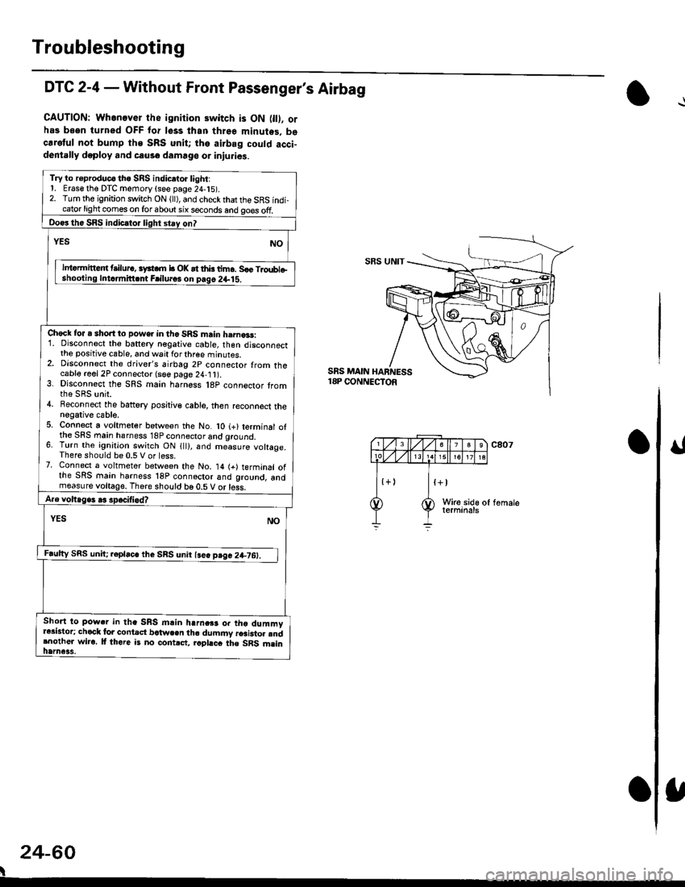
DTC 2-4 - Without Front Passenger's Airbag
CAUTION: Whenever the ignition switch is ON 0l). orhas been turned OFF for lsss lhan three minutes. becaretul not bump the SRS unit; the airbag could acci-dentally doploy and causo damage or iniuries.
Try to r€produc€ tho SRS indic.to. light:1. Erase the DTC memory (see page 24,15).2. Turn the ignition switch ON (ll), and check that the SRS indi-cator light comes on for about six seconds and go€s off.
Do€rthe SRS indicrtor light stay on?
NOrEs
lntormitteit t ilur., iyst m b OK at thb tim6. Sle Troubleshooling Intdmitt.nt Frilu.os on pag6 2+lS.
Check for a short to power in the SRS main h.rna3s:1. Disconnect the baftery negative cable, then disconnectthe positive cable, and wait for three minutes.2. Dlsconnect the driver's airbag 2p connector from thecable reel 2P connector (see page 24,11).3. Dlsconnect the SRS main harness l8p connector tromthe SRS unit.4. Beconnect the battory positiv€ cable, then reconnect thenegative cable.5. Connect a voltmeter between the No. lO (+) terminal ofthe SFS main hsrness 18P connector and qround.6. Turn the ignition switch ON {ll), and me-asure voltage.There should be 0.5 V or less.7. Connect a voltmeter between the No. 14 (+) terminal ofthe SRS main harness 18P connoctor and ground, andmeasure voltage. There should be 0.5 V or less.
A.e voltage. .3 spocifi.d?
YES NO
F.ulty SRS uniC .epla"" tl,. SnS unn l""" p"g" 2+7O:_l
Short to pow.r in tha SRS mlin harnc$ or tho dummyr*istor; chock lor contact bctwcen th. dummy r6ai3to. rndrnother wiro. lf there is no contrct, rcphcc the SRS msinhame3s.
SBS UNIT
SRS MAIN18P CONNECTOR
24-60
I
Page 1799 of 2189
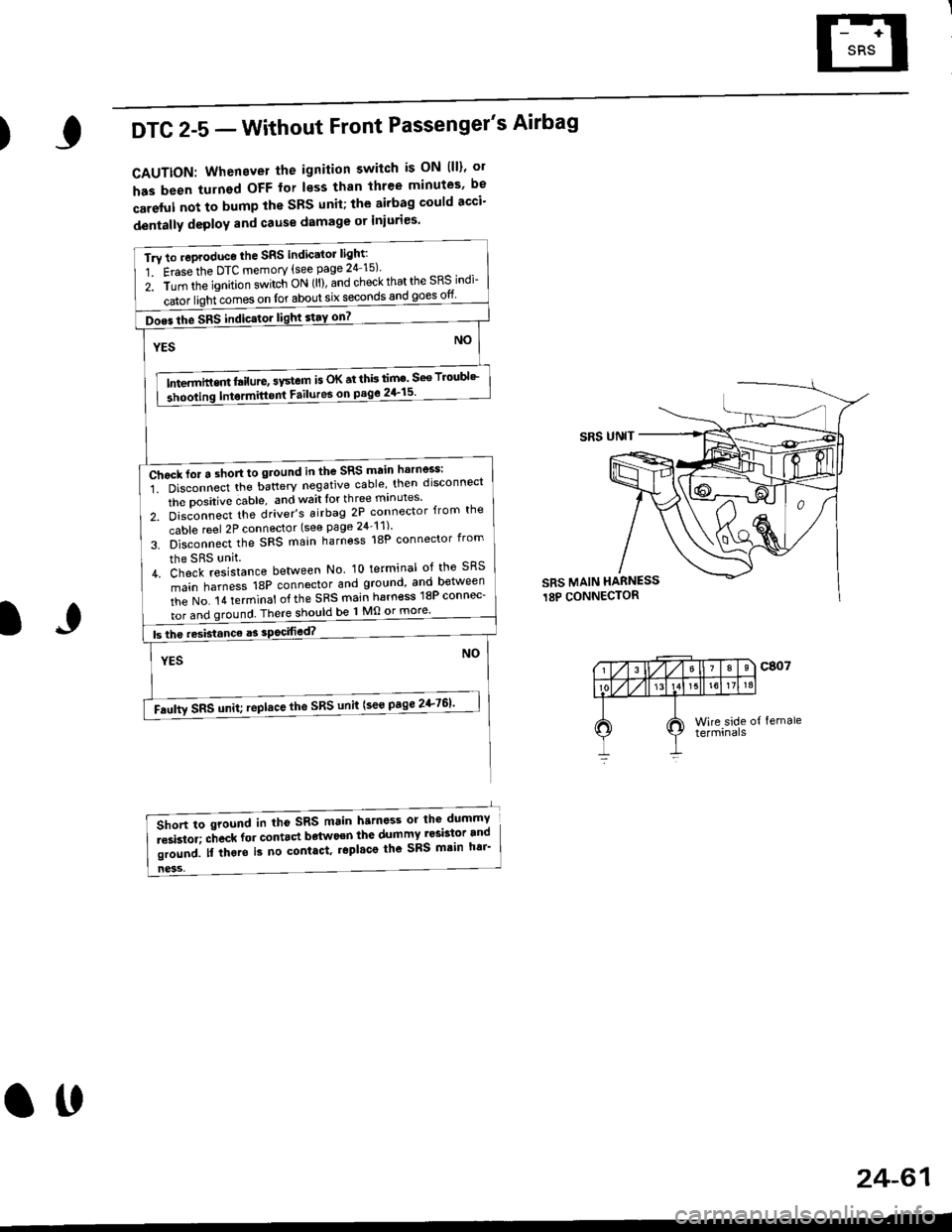
)DTC 2-5 - Without Front Passenger's Airbag
CAUTTON: Whenever the ignition switch is ON lll)' ol
has been turnsd OFF for less than three minutes' be
careful not to bump the SBS unit; the airbag could acci'
dentally deploY and Gause damage or iniuries'
Tru to .oproduce the SRS indic'tor light:
1 Erasethe DTC memory {see page 24 15)'
z. irin tfie ignition s.itch ON (ll), and check that the SRS indi-
iatoi ligiricomes on for about six seconOs and goes otf
Does the SRS indic.tor light stay on7 |
NOYES
tn---t",-in"m l"itrt", "v"tem is oK at thb lim' seo Troubl'-
3hooling Intormitt6nt Failures on pago 2+15'
ffih",n"""'i. oi""onn""t ttte u"tt"ry negative cable' then disconnect
the Dositive dable, and wait lor th ree mrnutes'
z. 6i"J-"""a tt'" driver's airbag 2P connector {from the
cable reel 2P connector (see page 24_11)'
s. b]""onn""t,f'" SFS main harness 18P connector from
the SRS unit.
L di"lfi""i"on." between No lo terminal of the sRS
main harness 18P connector and ground and between
iie t'lo. t a terminat of the SRS main harn€ss 18P connec-
I tor and ground There should be 1 Mo or more'
I btheresistanceasso444g14�._���._��
NOYES
-Faulty sRs unit; ,epltce the sRs unit (see page 2+761'
SRS UNIT
SRS MAIN HARNESS
18P CONNECTOR
IJ
ness,
6lort to sround in tho sRS main harness or the dummY
i""i"toi; "-ft""* fot "ont.ct bdtwo€n the dumTI Iesbt9r.and
li"r"J. n irt"t" is no contact. r6pl'co the sRs mtin h6i'
24-61
ott
Page 1807 of 2189
)
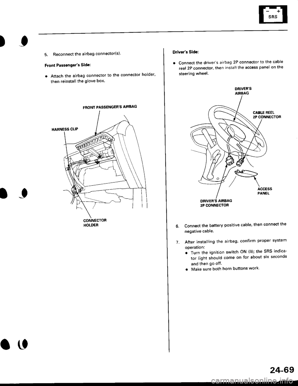
5, Reconnect the airbag connector(s)'
Front Passengor's Side:
a Attach the airbag connector to the connector holder'
then reinstallthe glove box.
FRONT PASSENGER'S AIRBAG
oo
24-69
Driver's Side:
a Connect the driver's airbag 2P connector to the cable
reel 2P connector, then install the acc€ss panel on the
steering wheel
DRIVER'S AIRBAG2P CONNECTOR
6. Connect the battery positive cable, then connect the
negative cable.
7. After installing the
operatlon:
. Turn the ignition
tor light should
and then go off
a Make sure both horn buttons work
airbag, confirm Proper sYstem
switch ON (ll); the SRS indica-
come on for about six seconds
Page 1809 of 2189
E-
)I
Connect a 12 volt battery to the tool:
. lf the green light on the tool comes on, the aar-
bag igniter circuit is defective and cannot deploy
the airbag. Go to Damaged Airbag Special
Procedure.
. lf the red light on the tool comes on, the airbag is
ready to be deployed.
Push the tool's deployment switch. The airbag
should deploY (deployment is both highly audible
and visible; a loud noise and rapid inflation of the
bag, followed by slow deflation).
. lf the airbags deploy and the green light on the
tool comes on. continue with this procedure.
. l{ an airbag doesn't deploy, yet the green light
comes ON, its igniter is defective. Go to Dam-
aged Airbag Special Procedure.
!!@ During doployment, the airbag sssom'
bly can become hot enough to buln you. Wait thir'
ty minutes aftsr deployment belore touching tho
assembly.
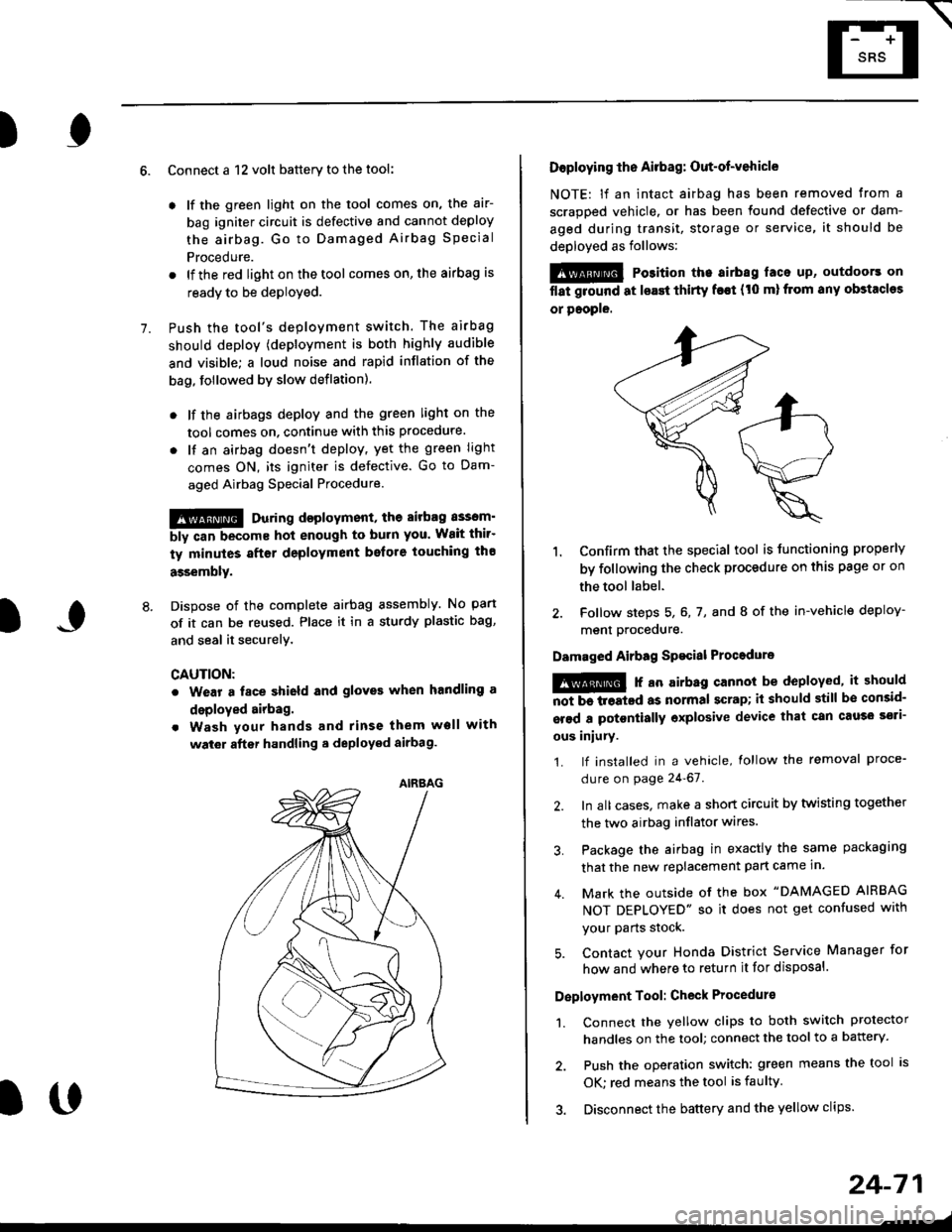
Dispose of the complete airbag assembly. No part
of it can be reused. Place it in a sturdy plastic bag,
and seal it securelY,
CAUTION:
. Wear a fsce shield and gloves when handling a
deployed airbag.
. Wash your hands and rinse them well with
wat6r after handling. deployed airbag.
t('
24-71
7.
AIRAAG
Doploying th6 Airbag: Out-of-vehicle
NOTE: lf an intact airbag has been removed from a
scrapped vehicle. or has been found defective or dam-
aged during transit, storage or service, it should be
deployed as follows:
@ Po3ition the airbag laca up, outdoors on
flat ground at lsast thirty f€€t (t0 ml from any obstacles
or people.
1. Confirm that the special tool is tunctioning properly
by following the check procedure on this page or on
the tool label.
2. Follow steps 5, 6, 7, and I of the in-vehicle deploy-
menl Drocequre.
Damaged Airbag Spacial Procedure
!@ r an airb.g cannot be deployed, it should
iiiTi-treatcd as normal scrap; il should still be consid-
srsd a potontially oxplosive device that can cau3o ssti-
ous iniury.
1. lf installed in a vehicle, lollow the removal proce-
dure on page 24-67.
2. In all cases. make a short circuit by twisting together
the two airbag inflator wires.
3. Package the airbag in exactly the same packaging
that the new replacement part came in.
4. Mark the outside of the box "DAMAGED AIRBAG
NOT DEPLOYED" so it does not get confused with
your Parts stock.
5. Contact your Honda District Service Manager for
how and where to return it for disposal.
Deployment Tool: Check Procedur€
1. Connect the yellow clips to both switch protector
handles on the tool; connect the tool to a battery.
2. Push the operation switch: green means the tool is
OK: red means the tool is faulty
3. Disconnect the battery and the yellow clips.
Page 1813 of 2189
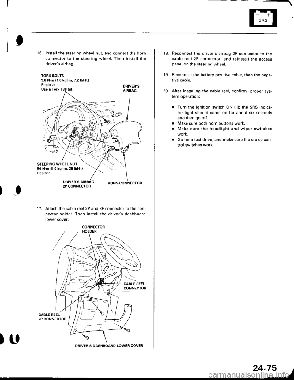
16. Install the steering wheel nut, and connect the horn
connector to the steering wheel. Then install the
driver's airbag.
TORX SOLTS9.8 N m 11.0 kgf m, 7.2 lbtftlReplace.Use a Torx T30 bit.
STEERING WHEEL NUT50 N.m 15.0 kgf.m,36lblft)Replace.
DRIVEB'SAIRBAG
DRIVER'S2P CONNECTOBHORN CONNECTOB
I
17.Attach the cable reel 2P and 3P connector to the con-
nector holder. Then install the driver's dashboard
lower cover.
)UDRIVER'S DASHBOARD LOWER COVER
24-75
18. Reconnect the driver's airbag 2P connector to the
cable reel 2P connector. and reinstall the accesspanel on the steering wheel.
19. Reconnect the battery positive cable, then the nega-
tive cable.
20. After installing the cable reel, confirm proper sys-
tem operation:
Turn the ignition switch ON (ll); the SRS indica-
tor light should come on for about six seconds
and then go off.
Make sure both horn buttons work.
Make sure the headlight and wiper switches
Go for a test drive, and make sure the cruise con
trol switches work.
a
a
Page 1815 of 2189
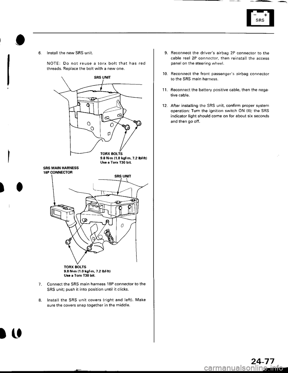
6. Install the new SRS unit.
NOTE: Do not reuse a torx bolt that has red
threads. Replace the bolt with a new one.
)
7.
TORX BOLTS9.8 N.m l'1.0 kg{.m, 7.2 lbf.ft}Use a Torx T30 bit.
Connect the SRS main harness l8P connector to the
SRS uniu push it into posjtion until it clicks.
Install the SRS unit covers (ri9ht and left). Make
sure the covers snap together in the middle.
8.
TORX BOLTS9.8 N.m 11.0 kgf.m, 7.2 lbf.ft)U3e . Torx T30 bit.
SRS MAIN HARNESS
)(l
9.
10.
't2.
Reconnect the driver's aibag 2P connector to the
cable reel 2P connector, then reinstall the access
panel on the steering wheel.
Reconnect the tront passenger's airbag connector
to the SRS main harness.
Reconnect the battery positive cable, then the nega
tive cable.
After installing the SRS unit, confirm proper system
operation: Turn the ignition switch ON (ll); the SRS
indicator light should come on for about six seconds
and then go oif.
11.
24-77
.-