Page 1759 of 2189
)r
l,.l
I
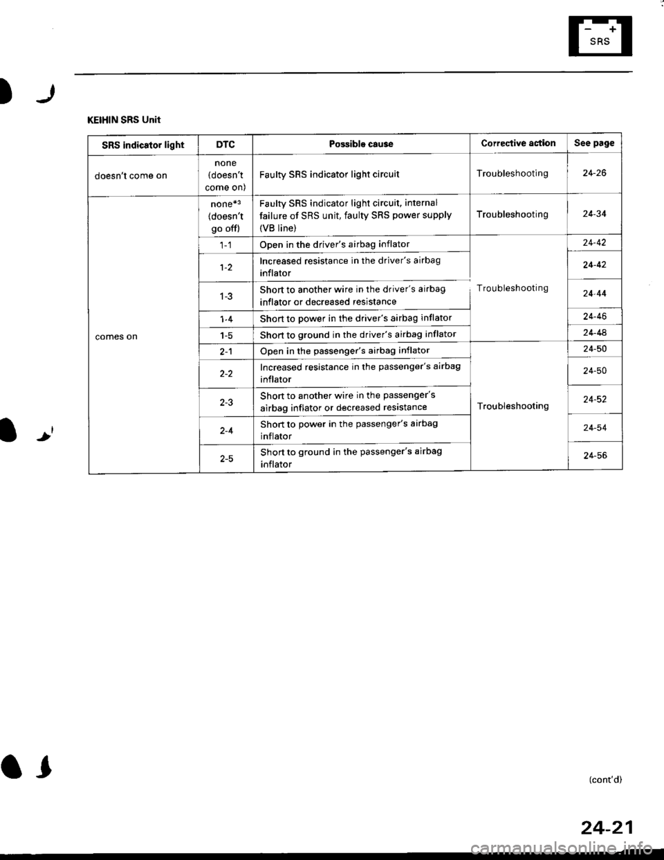
KEIHIN SRS Unit
SRS indicator lightDTCPossible cau3eCorrective astionSee page
doesn't come on
none
(doesn't
come on)
Faulty SRS indicator light circuitTroubleshooting24-26
comes on
none*3
(doesn't
go offl
Faulty sRs indicator light circuit, internal
failure of SRS unit, faulty SRS power supply
{VB line)
Troubleshooting24-34
Open in the driver's airbag inflator
Troubleshooting
24-42
1-2Increased resistance in the driver's airbag
inflator24-42
1-3Short to another wire in the driver's airbag
inflator or decreased resistance24-44
1-4Short to power in the driver's airbag inflator24-46
1-5Short to ground in the driver's airbag inflator24-44
2-1Open in the passenger's airbag inflator
Troubleshooting
24-50
Increased resistance in the passenger's airbag
inflator24-50
Short to another wire in the passenger's
airbag inflator or decreased resistance24-52
2-4Short to power in the passenger's airbag
inflator24-54
Short to ground in the passenger's airbag
inflator24-56
(cont'd)
24-21
Page 1760 of 2189
Troubleshooting
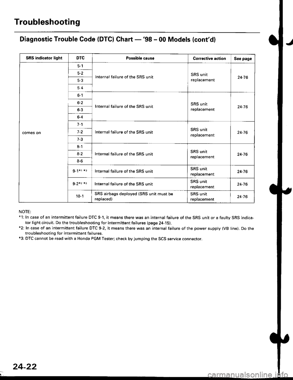
Diagnostic Trouble Code (DTCI Ghart -'98 - 00 Models (cont'd)
NOTE:*l: In case of an intermittent failure DTC 9-1. it means there was an internal failure of the SRS unit or a faultv SRS indica-
tor light circuit. Do the troubleshooting for intermiftent failures (pa9e 24-15).*2: In case of an intermittent failure DTC 9-2, it means there was an internal failure of the power supply (VB line). Do thetroubleshooting for intermittent failures.*3: DTC cannot be read with a Honda PGM Tester; check by jumping the SCS service connector.
SRS indicator lightDTCPossible causeCorective actionSeo page
comes on
5-2
53
54
lnternal failure of the SRS unitSRS unit
replacement24-7 6
6-1
6-2
_
64
Internal failure of the SRS unitSRS unit
replacement24-16
n
-
8l
8S
9_1*r *3
Internal failure of the SRS unitSRS unit
reptacement24-76
Internal failure of the SRS unitSRS unit
replacement24-76
Internal failure of the SRS unitSRS unit
replacement24-76
Internal failure of the SBS unitSRS unit
reptacemenr24-76
10-1SRS airbags deployed (SRS unit must be
reDlaced)
SRS unit
replacement24-76
24-22
Page 1761 of 2189
)r
l-J
SIEMENS SRS Unit
SRS indicator lightDTCPossible cause Corregtive astionSee page
doesn't come on
none(doesn't
come on)
FaulW SRS indicator light circuitTrou bleshooting24-26
comes on
none*3
(doesn't
go ofl)
Faulty SRS indicator light circuit, internal
failure of SRS unit, faulty SRS power supply
{VB line)
Troubleshooting24-34
1-1Open or increased resistance in the driver's
airbag inflator
Troubleshooting
24,42
1-3Short to another wire in the driver's airbag
inflator or decreased resistance24-44
1-4Short to power in the driver's airbag inflator24-46
Shon to ground in the driver's airbag inflator24 48
2-1Open or increased resistance in the passengers
airbag inflator
Troubleshooting
24-50
2-3Short to another wire in the passenger's
airbag inflator or decreased resistance24-52
2-4Short to power in the passenger's airbag
inflator24-54
2-5Short to ground in the passenger's airbag
inflator24-56
,-. ^
l) t (cont,d)
24-23
d
Page 1762 of 2189
Troubleshooting
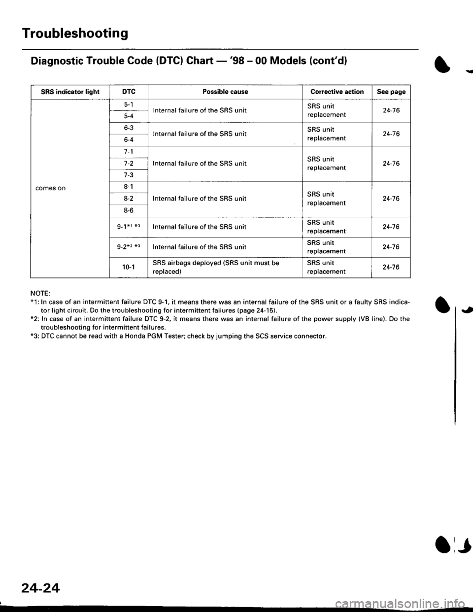
Diagnostic Trouble Code (DTG) Chart -'98 - 00 Models (cont'dl
NOTE:*'l: In case of an intermittent failure DTC 9-1. it means there was an internal failure of the SRS unit or a faulty SRS indica-
tor light circuit. Do the troubleshooting for intermiftent failu.es (page 24-15).*2: In case ot an intermittent failure DTC 9-2. it means there was an internal failure of the power supply (VB line). Do the
troubleshooting for intermift ent failures.*3: DTC cannot be read with a Honda PGM Tester; check by jumping the SCS service connector.
24-24
a,
SRS indicator lightDTCPossible causeCorective actionSee page
comes on
lnternal failure of the SRS unitSRS unit
repracemenl24-765-4
6-3lnternal failure of the SRS unitSRS unit
reptacemenr24-766-4
Internal failure of the SRS unitSRS unit
replacement24-7 6
8-1
lnternal failure ot the SRS unitSRS unit
replacement24-7 68-2
8-6
g_1*r *rInternal failure of the SRS unitSRS unit
replacement24-16
lnternal failure of the SRS unitSRS unit
repracemenl24-76
10-1SRS airbags deployed (SRS unit must be
.eplaced)
SRS unit
reptacemenl24-76
Page 1763 of 2189
SRS Indicator Light Wire Connections
SRS Indicator Light Power Circuit
DASHBOARD WIRE HARNESS
To UNDER-DASHFUSE/RELAY BOX -
20P CONNECTOR
SRS Indicato. Light Control Circuit
To SRS UNIT
tI
SRS MAIN HARNESS
C41 1, C412 : Terminal sido of mdlo t6rminalsC501, C5O2, C508, C801. C802, C807 : Wi.6 sidc of fomalo t.rminals
MAIN WIBE HARNESS
BLU
C508 -+ To GAUGE ASSEMBLY
c41 1
To GAUGE ASSEMBLY
at
C501 : DASHBOARDWIRE HARNESS 2oP CONNECTORC508 : DASHBOARD wlRE HARNESS 5P CONNECTORC801 : SRS MAIN HARNESS 2P CONNECTORC807 : SRS MAIN HARNESS 18P CONNECTOR
C802 : SRS MAIN HARNESS 3P CONNECTORC412 : MAIN WIRE HARNESS 3P CONNECTORC41 1 : MAIN WIRE HARNESS 24P CONNECTORC502 : DASHBOARD WIRE HARNESS 24P CONNECTOR
GRY
OI
24-25
Page 1764 of 2189
Troubleshooting
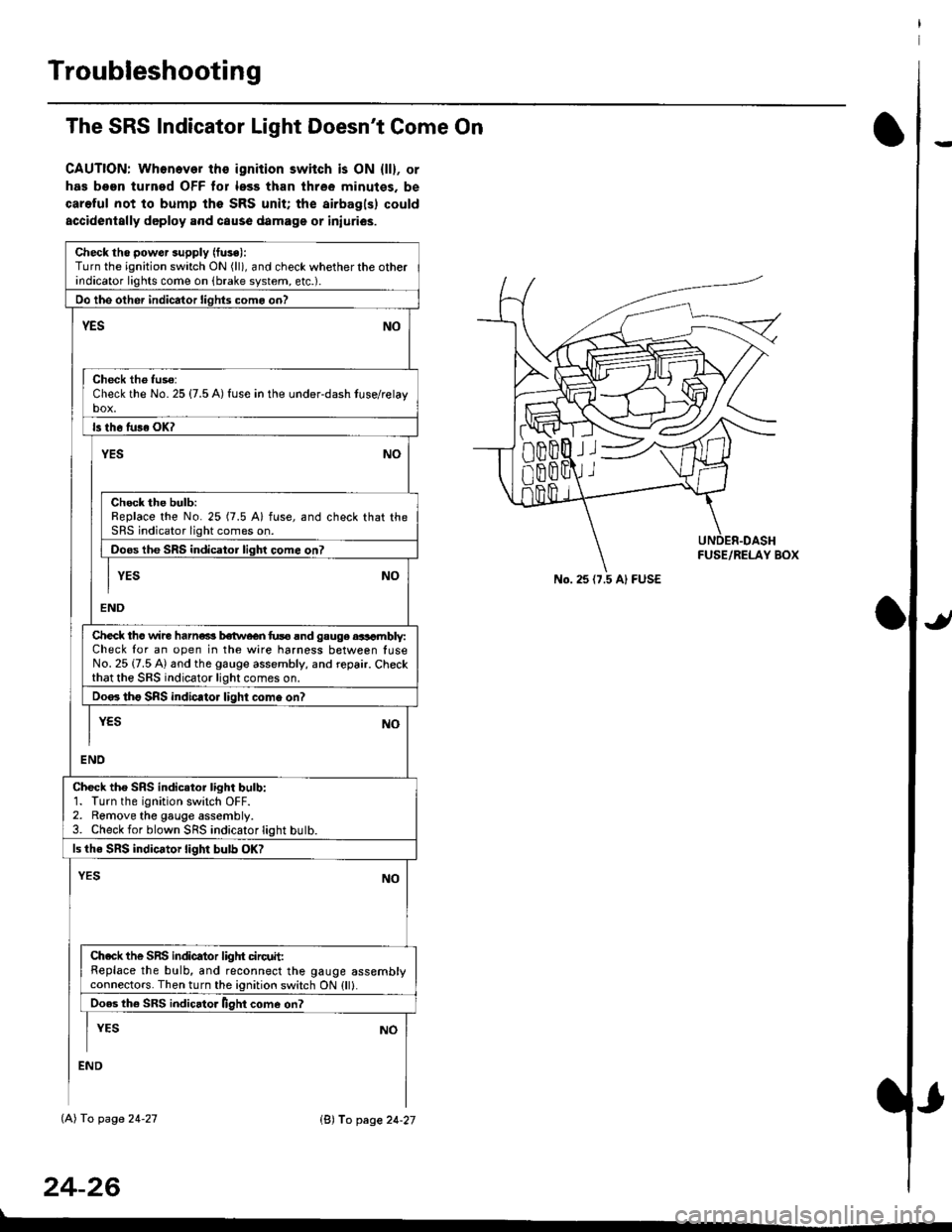
The SRS Indicator Light Doesn't Come On
CAUTION: Whonever ths ignition switch is ON {ll}, or
has been turned OFF tor less than three minutes. be
careful not to bump the SRS unit; the airbagls) could
accidentally deploy .nd caus6 damage or iniuri€s.
Check tho pow€r supply (fuse):
Turn the ignition switch ON (ll), and check whether the otherindicator lights come on (brake system, etc.).
Oo the other indicator liohts como on?
YESNO
Check th6 fuso:Check the No. 25 {7.5 A) fuse in the under-dash tuse/relayb"t
ls th6 tu36 OK?
NOYES
Check the bulb:Replace the No. 25 (7.5 A) fuse, and check that theSRS indicator light comes on.
Doos the SRS indicator liqhl come on7
I YES No
END
Check tho wire harns b€twecn fus6 and gauge aasambly:Check for an open in the wire harness between luseNo. 25 {7.5 A) and the gauge assembly, and repair. Checkthat the SRS indicator light comes on.
Doo. tho SRS indic.tor light como on?
I yEs No
I
END
Check tho SRS indicator light bulb:1. Turn the ignition switch OFF.2. Remove the gauge assembly.3. Check for blown SRS indicator light butb.
ls the SRS indicator light bulb OK?
NOYES
Ch.ck the SnS indicator liglrt circuit:Replace the bulb, and reconnect the gauge assemblyconnectors. Then turn the ignition switch ON {ll}.
Ooes th6 SRS indicato. llght come on?
I YEs No
:ND
lAl To page 24-27
24-26
lB'J fo page 24-27
))
No. 25 (7.5 Al FUSE
Page 1765 of 2189
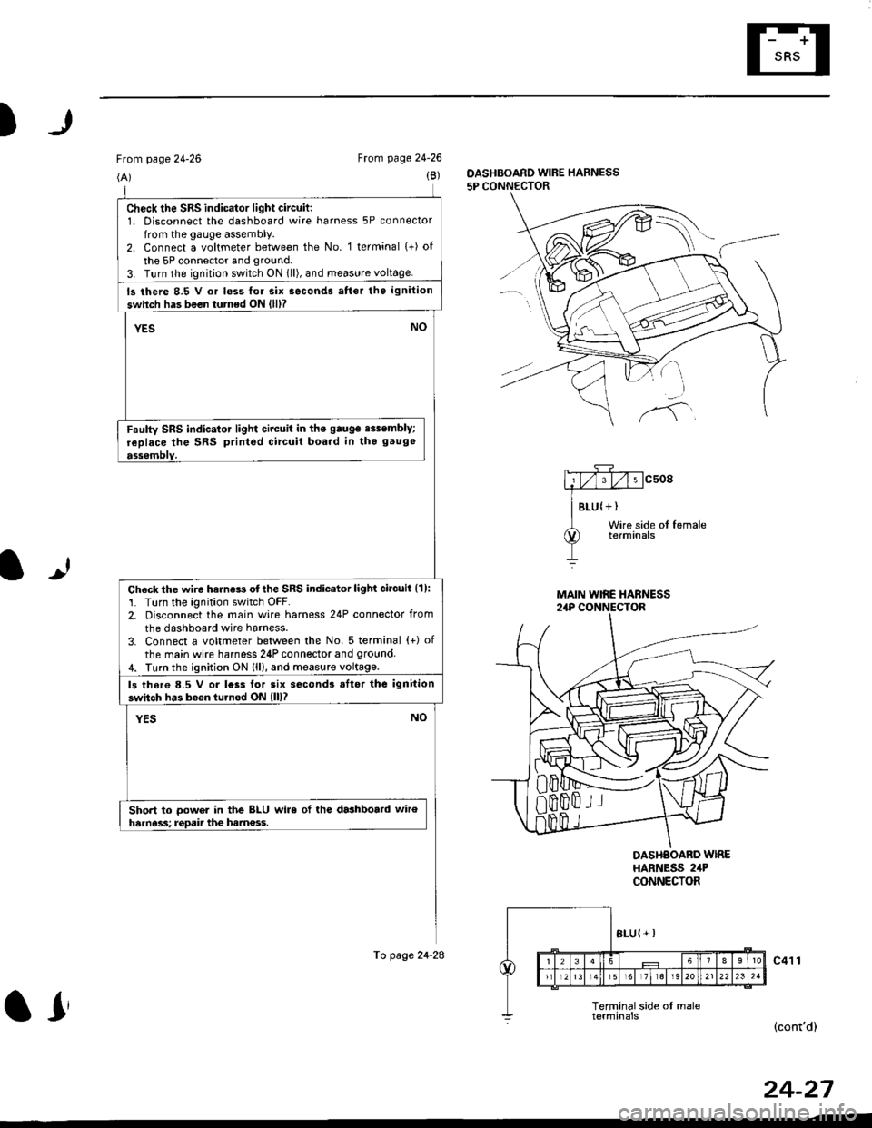
)
From page 24-26
(A)
From page 24-26
(B)DASHBOARD WIRE HARNESS
5P CONNECTOR
It
MAIN WIRE HARNESS2,rP CONNECTOR
DASHAOARD WIREHARNESS 2irPCONNECTOR
c41 1
(cont'd)
24-27
check the sRs indicator light circuit:1. Disconnect the dashboard wire harness 5P connector
from the gauge assembly.2. Connect a voltmeter between the No. 1 terminal (+) of
the 5P connector and ground.
3. T!rn the ignition switch ON 1ll), and meas!re voltage.
ls there 8.5 V or loss lor six seconds atter the ignition
swilch has been turned ON {lll?
YESNO
Faulty SRS indicator light circuit in the gauge e$embly;
replace the SRS printed circuit boa.d in tho gauge
ass€mblY.
Check the wire harness otthe SRS indicator light circuil {1):'1. Turn the ignition switch OFF.2. Disconnect the main wire harness 24P connector from
the dashboard wire harness.
3. Connect a voltmeter between the No. 5 terminal {+) of
the main wire harness 24P connector and 9round4. Turn the ignition ON (ll), and measure voltage.
ls thore 8.5 V or lcss tor tix second3 .Itor the ignition
switch has b6en turned ON lll)?
YESNO
Short to oower in the BLU wire ol the dashboald wiroharness; rgpaii the ham€ss.
To page 24-28
ar
Page 1766 of 2189
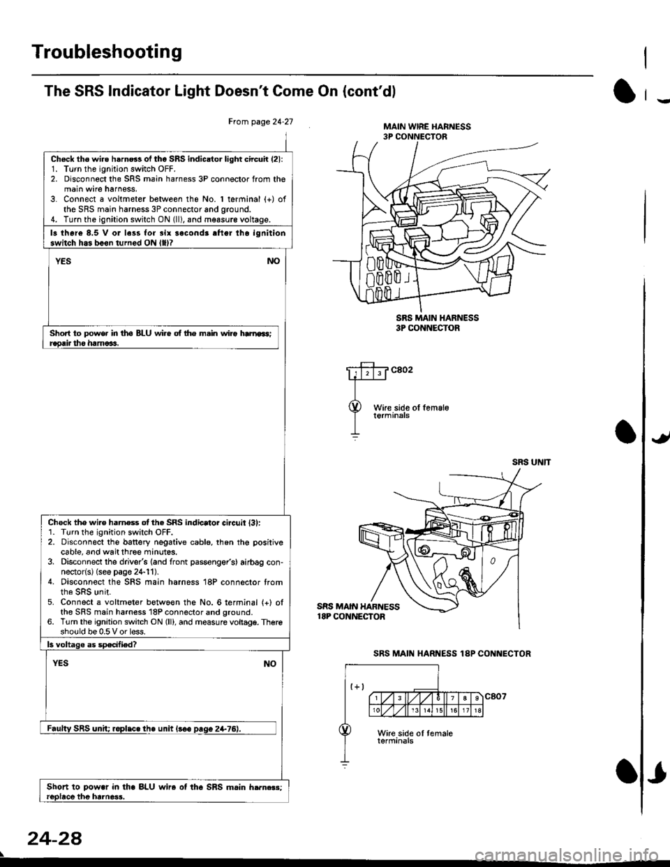
Troubleshooting
The SRS Indicator Light Doesn't Come On (cont'dl
Frcm page 24.21
Ch6ck tho wire h6rn6s of tho SRS indicator light circuir (21:
1. Turn the ignition switch OFF.2. Disconnect the SRS main harness 3P connector from themain wire harness,3. Connect a voltmeter between the No. 1 terminal (+) ofthe SRS main harness 3P connector and ground.4. Turn the ignition switch ON (ll), and measur€ voltage.
13 thore 8.5 V or less for 3ir sacond3 aftgr tho ignitionswitch h.3 b.en turned ON llllT
YESNO
Short to power in tho BLU wi.e of lhe m.in wiro hrnroas;r€orir tho ham6as.
Chock the wi.e harness otthe SRS indicator ci.cuit l3l:1. Turn the ignition switch OFF.2. Disconnect the banery negative cable. th6n the positivecable, and wait three minutes.3. Disconnect the driver's (and front passenger's) airbag con-nector{s} (seo page 24-11).4. Disconnect the SRS main harness 18P connector trom
5. Connect a voltmeter betwo€n the No. 6lerminal {+} ofthe SRS main harness 18P connector and ground.6. Turn the ignition switch ON (ll), and measure vollagg. Thereshould be 0.5 V or less.
ls voltago as specified?
YESNO
Faultv SRS unh; roplic. the unit l!€e paqo 2+76).
Shoft to Dowar in tha BLU wire ot tho SRS mein h.rn.r3:reobce the hrlne3s,
24-2a
SRS MAIN HARNESS18P CONNECTOR
MAIN WIRE I{ARNESS3P CONNECTOR
SRS MAIN I{ARNESS3P CONNECTOR
c802
SRS UNIT
SRS MAIN HARNESS 1AP CONNECTOR
-