Page 1655 of 2189
Ceiling Light Test
1. Turn the light switch OFF
2. Pry off the lens.
3. Remove the two mounting nuts (or a bolt) from the
housing, then remove the housing.
4. Disconnect the connector{s) from the housing.
5. Check for continuity between the terminals in each
switch position according to the table.
With moonroof:
3P CONNECTOR
rermrnal
Position \
12or2'
3or3'�
OFFo-/a\-o\7
MIDDLEo-,.\--o\:/
ONo---o\:/
23-185
q,
Without moonroot:
Coupe/Hatchback:
BULB (5 WI
/
2'
4
1
3
Page 1656 of 2189
Interior Lights
Spotlights Test
1. Turn the spotlight switch OFF.
2. Pry off the lens.
3. Remove the two screws and the housing.
4. Disconnect the 1P connector from the housing.
5. Check for continuity between the terminals in each
switch position according to the table.
Terminal
t*'*-__\234
OFFo-{e,
//:\
--o
--o\:,/
ONo--*i@
/a\
-_o
--o\:.,/
23-186
Trunk Light Test
1. Open the trunk light cover from the housing.
2. Pry out the light assembly.
3. Disconnect the 2P connector from the housing,
4. Make sure that the bulb is OK. Check for continuitybetween the No. 1 (+) and No.2 (-) terminals.
EULB {.')
*1 3.4 W: USA, Canada-oroduced5 W: Japan-produced
Page 1659 of 2189
UNDER DASHFUSE/RELAY 80X
r*.i,,";l
I
I
I
I
I
I
IYEUFEDWHTiELU
Circuit Diagram ('96 - 98 modelsl
A15A16
NoJ0 (7 sA)
v
IRED]BLK
RED
I
I
I
J
DASH LIGHTSBRIGHTNESSCONTROLLER
ANTENNALEAD
BRN/WHTBLK
G501
LEFT FHONTDOOF SPEAKER
I RED,^/Er
ILI�l
RIGHT REARSPEAKER
I BLU/YEL
III�t
SPEAKER
q-
IGN TION SWITCHUNDER.HOOD FUSE/FELAY BOX
AUDIO UN T(STEREO RAOLO TUNER)
@
LEFTRIGHTTWEETER
GRY]BLK
23-189
Page 1662 of 2189

Stereo Sound System
Stereo Radio Tuner Terminals
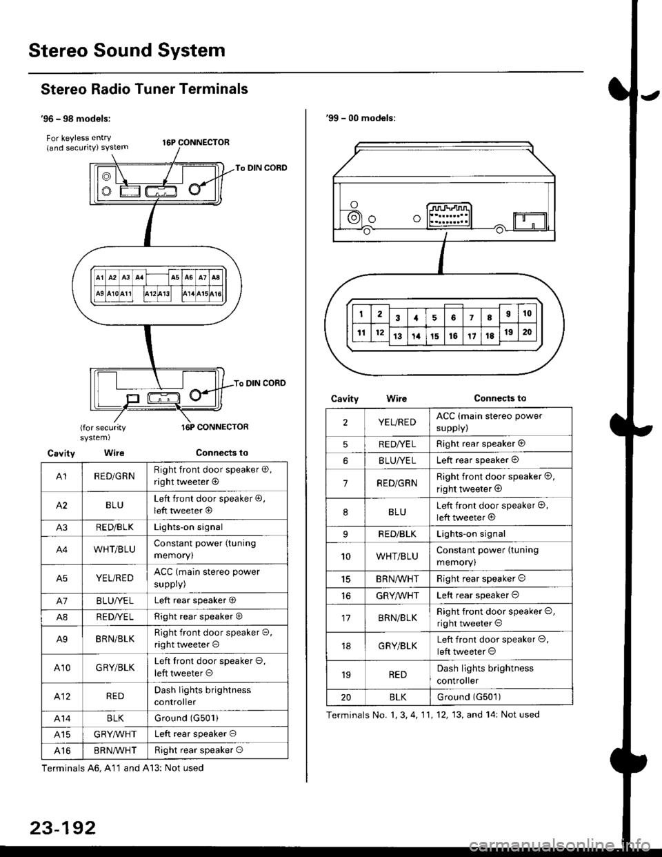
'96 - 98 models:
For keyless entry . t6p coNNEcroR(and securrty) syslem
To DIN CORD
To DIN CORD
(for securitysystem)
Cavity Wire
A1RED/GRNRight front door speaker o,
right tweeter @
BLULeft front door speaker @,
left tweeter @
A3RE D/B LKLights-on signal
A4WHT/BLUConstant power (tuning
memoryl
A5YEL/REDACC (main stereo power
suppry)
A7BLUI/ELLeft rear speaker O
A8RE DI/E LRight rear speaker O
A9BRN/BLKRight front door speaker O,
right tweeter o
A10GRY/BLKLeft tront door speaker O,
left tweeter O
412REDDash lights brightness
controller
A14BLKGround (G501)
415GRYMHTLeft rear speaker O
Al6BR N/VVHTRight rear speaker O
Terminals A6, A11 and A13: Not used
23-192
'99 - 00 models:
CsvityConnccts toWire
2YEL/REDACC (main stereo power
suppry)
5RE DI/E LRight rear speaker @
BLUI/ELLeft rear speaker @
7RED/GRNRight front door speaker @,
right tweeter @
8BLULeft front door speaker @,
left tweeter @
9RED/BLKLights-on signal
10WHT/BLUConstant power (tuning
memory)
15BRN,ryVHTRight rear speaker O
GRYMHTLeft rear speaker O
17BRN/BLKRight front door speaker O,
right tweeter O
18G RY/BLKLeft front door speaker O,
left tweeter O
'19REDDash lights brightness
controller
20BLKurouno t(l5u t,
Terminals No. 1, 3, 4, 11,12, 13, and 14: Not used
Page 1664 of 2189
Stereo Sound System
Window Antenna Wire Test
1. Wrap aluminum foil around the tip of the tester
probe as shown.
Touch one tester orobe to the window antenna ter-
minal near, and move the other tester probe along
the antenna wires to check that continuity exists.
WINDOW ANTENNA
23-194
OPEN
Window Antenna Wire Repair
NOTE: To make an effective repair, the broken section
must be no longer than one inch.
1. Lightly rub the area around the broken section with
fine steel wool, then clean it with alcohol.
2. Carefully mask above and below the broken portion
of the window antenna wire with cellophane tape.
CELLOPHANETAPE
Using a small brush, apply a heavy coat of silver
conductive paint extending about 1/8" on both
sides of the break, Allow 30 minutes to dry.
NOTE| Thoroughly mix the paint betore use.
Check for continuity in the repaired wire.
Apply a second coat of paint in the same way. Let it
dry three hours before removing the tape.
Page 1669 of 2189

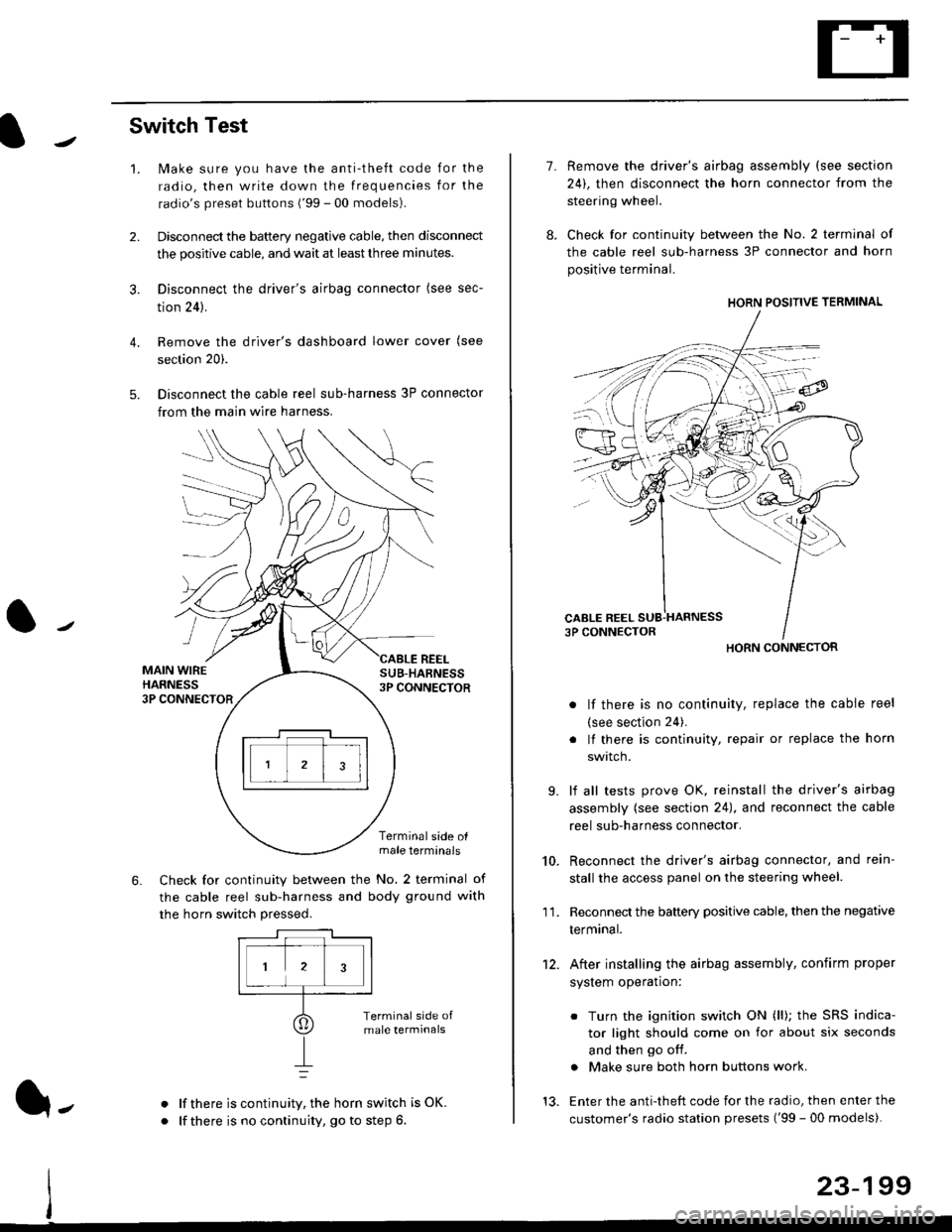
Switch Test
lMake sure you have the anti-theft code for the
radio, then write down the frequencies for the
radio's preset buttons ('99 - 00 models).
Disconnect the battery negative cable, then disconnect
the positive cable, and wait at least three minutes.
Disconnect the driver's airbag connector (see sec-
tion 24).
Remove the driver's dashboard lower cover (see
section 20).
Disconnect the cable reel sub-harness 3P connector
from the main wire harness.
2.
3.
4.
5.
1.
MAIN WIREHARNESS3P CONNECTOR
SUB-HABNESS3P CONNECTOR
REEL
6.
Terminalside olmale terminals
Check for continuity between the No. 2 terminal of
the cable reel sub-harness and body ground with
the horn switch pressed.
alf there is continuity, the horn switch is OK.
lf there is no continuity, go to step 6l-
-\
1.
8.
10.
'I 1.
9.
Remove the driver's airbag assembly (see section
24), then disconnect the horn connector from the
steering wheel.
Check for continuity between the No. 2 terminal of
the cable reel sub-harness 3P connector and horn
positive terminal.
lf there is no continuity, replace the cable reel
(see section 24).
lf there is continuity, repair or replace the horn
swtlcn,
lf all tests prove OK, reinstall the driver's airbag
assembly (see section 24), and reconnect the cable
reel sub-harness connector.
Reconnect the driver's airbag connector, and rein-
stall the access panel on the steering wheel.
Reconnect the battery positive cable, then the negative
termtnar.
After installing the airbag assembly, confirm proper
system operation:
12.
Turn the ignition switch ON (ll); the SRS indica-
tor light should come on for about six seconds
and then go off.
Make sure both horn buttons work.
13. Enter the anti-theft code for the radio, then enter the
customer's radio station presets ('99 - 00 models).
HORN CONNECTOR
23-199
Page 1674 of 2189

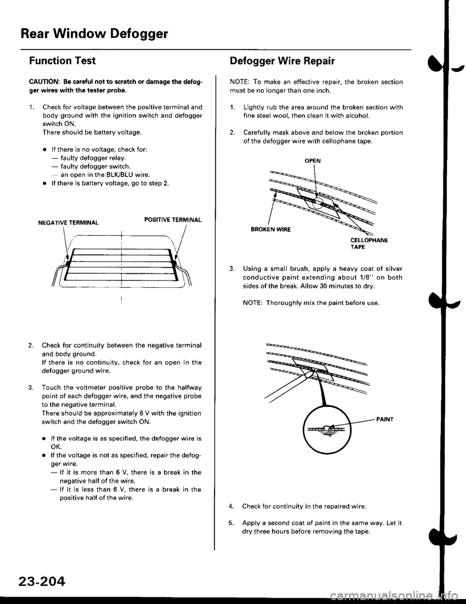
Rear Window Defogger
Function Test
CAUTION: Bs careful nol to scralch or damage the defog-
ger wires with the tester probe,
'1. Check for voltage between the positive terminal and
body ground with the ignition switch and defogger
switch ON.
There should be banery voltage.
. lf there is no voltage, check for:- faulty defogger relay.- faulty defogger switch.
an ooen in the BLK,/BLU wire.
. lf there is battery voltage, go to step 2.
POSITIVE TERMINAL
2. Check for continuity between the negative terminal
and body ground.
lf there is no continuity, check for an open in the
defogger ground wire.
Touch the voltmeter positive probe to the halfway
point of each defogger wire, and the negative probe
to the negative terminal.
There should be approximately 6 V with the ignition
switch and the defogger switch ON.
. lf the voltage is as specified. the defogger wire is
oK.
. lf thevoltage is not as specified, repairthe defog-
ger wrre.- lf it is more than 6 V, there is
negative half of the wire.- lf it is less than 6 V, there is
positive half of the wire.
a break in the
a break in the
23-204
OPEN
?
Defogger Wire Repair
NOTE: To make an effective repair, the broken section
must be no longer than one inch.
1, Lightly rub the area around the broken section with
fine steel wool, then clean it with alcohol.
2. Carefully mask above and below the broken portion
of the defogger wire with cellophane tape.
CELLOPHANETAPE
Using a small brush, apply a heavy coat of silver
conductive paint extending about 1/8" on both
sides of the break. Allow 30 minutes to dry.
NOTE: Thoroughly mix the paint before use.
Check for continuity in the repaired wire.
Apply a second coat of paint in the same way. Let it
dry three hours before removing the tape.
Page 1711 of 2189
Circuit Diagram
N0.30 (7.5A)
f/
IREO/BtX
WNT/BLK +WNT
BLU/RED
VHORN
IJ,
JRN,/WH
VgRAKELGHTS
UNDER.HOOD FUSEi RELAY 8OXUNDEB.OASH FUSARELAY BOX
GRY + BLUiGRN
GAUGEASSEMBLY
CBUISECONTROLACTUATOR
N0.41 (80A) N0.42 {40A)
INOICATORLIGHT(0.84rY)
lPIO SET
lo
I Q suue
tGNlTtoN swlrcH
l-t* : 99 00 models wlli A/T
23-241