Page 1587 of 2189

-
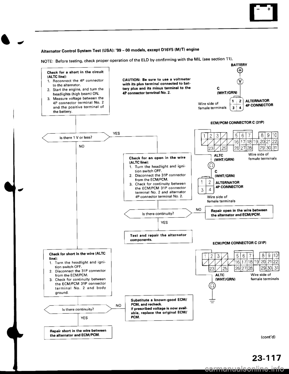
Alternator Control System Test {USA}: '99 - 0O models, except Dl6Y5 {M/T} engine
NOTE: Before testing, check proper operation ofthe ELD by confirming with the MIL (see section 11)'
BATTERY
CAUTION: Be sura lo use a voltmeter
with its plus te.minal conneqted io bat-
tery plus and it3 minus tgrminal to ths
4P connoctot tomrinal No. 2.
Wire side of
female terminals
c(WHT/GRNI
wire side offemale terminals
ALTERNATOR.P CONNECTOR
ECM/PCM CONNECTOR C 13lPI
ECM/PCM CONNECTOR C (31PI
(cont'd)
23-117
Check lor a sho.t in the circuit
{ALTC line):1, Beconnect the 4P connector
to the alternator.
2. Start the engine, and turn the
headlights (high beam) ON.
3. Measure voltage between the
4P connector terminal No. 2
and the Positive terminal of
the battery.
ls there 1 V or less?
Chcck for rn opon in the wire(ALTC lin6l:1. Turn the headlight and igni-
tion switch OFF
2. Disconnect the 31P connector
trom the ECM/PCM.
3. Check for continuity betlveen
the ECM/PCM 31P connectorterminal No. 2 and alternator
4P connector terminal No. 2
Repair opcn in the wire botweon
the alternstoi.nd ECM/PCM.ls there continuity?
Check tor short in the wire IALTC
line):1. Turn the headlight and igni-
tion switch OFF2. Disconnect the 31P connector
from the ECM/PCM.
3. Check for continuity between
the ECM/PCM 31P connector
terminal No. 2 and body
ground.
Substitute a known'good ECM/
PCM, and recheck.It prscribed voltagg is now avail'
abl€, replace tho original ECM/
PCM.
Raoair short in the wite between
the alle.nator and ECM/PCM,
1235618I10
/11611lo191 zo2122
23252621?82930JI
ALTC Wire side of(WHT/GRN) female terminals
o
Page 1601 of 2189
IJNOER,DASHFUSE/RELAY BOX
GAUGELIGHTS
l3wx4 l
CHARGINGSYSTEMLIGHT0.4w)
Gircuit Diagram
UNDEN HOOD FUSE/RELAY BOXIJ
N0.30 (7.54)FUSE
f7
I
tlRED/BLK BEO/BLK
l"l"8LK BLU
IJ
l'"^*
I
t-
G401G402
__l
tE2
IFED/BLU
CRUISECONTROTUNIT
fl ,,1:
tH
I c12
IFFD
VDASH LIGHTSBRIGHTNESSCONTROLLEF
l"'WHT/BLU
vALTERNATOR
(With shifi-up indicatd lighl)(wi1h cruise conlrcl system)
Page 1606 of 2189
Gauge Assembly
Bulb Locations (With Tachometer)
GAUGE LIGHT II.' WI
SEAT BELTREMINDER LIGHT I1.4 WI
LOW FUELLIGHT 13 W)
RIGHT TURN SIGNALINDICATOR LIGHT I1.4 WI
A/T GEARGAUGE LIGHTS 13 W)
CI{ARGING SYSTEM LIGHT (1.,1W)
GAUGE I-IGHT {1,4 WI
LOW ENGINE OIL PRESSUREINDICATOR LIGHT (1,' W}
HIGH EEAMINDICATOR LIGHT(1.4 W)
GAUGE LIGHT l3.il Wl
MALFUNCTIONINDICATORLAMP {MIL}BULE (1.{ Wl
WASHER I.'C VELINDICATOR LIGHT{1.4 Wl (Canada)
LEFT TURN SIGNALINDICATOR LIGHT {1.4 WI
sRsTOB (1.4 Wl
{On the printed circuit board)INDICATOR (1.12 x 6l(On the printed
circuit board)
ABS |ND|CATOR (1.. Wl{On the printed circuit board)CRUISE or SHIFT-UP INDICATOR 11.12 11.{On the orinted circuit board)
23-136
Page 1607 of 2189
JBulb Locations {Without Tachometer)
TRUNK INDICATORLIGHT {1.i1W}
.4 Wl
CHARGING SYSTEM LIGHT 11,4 W}
LTGHT (1.4 W)GAUGE LIGHT
SEAT BELTREMINDER LIGHT (1.4 WI
LOW ENGINE OIL PRESSUBE
INDICATOB LIGHT (1.4 WI
LOW FUEL INDICATORLrGl{T (3 W)
RIGHT TURN SIGNALINOICATOR LIGHT
(1.1Wt
GAUGE LIGHTS {3 WI
WASHER LEVELINDICATOR LIGHT{1.4 W} lcanad.l
HIGH BEAMINDICATOR LIGHTMALFUNCTIONINDICATORLAMP (MIL)
BULB {1.4 WI
{1.ilW)
LEFT TURN SIGNALINDICATOR LIGHT {1.4 WI
A/T GEAR POSITIONINDICATOR (1.12 x 6)(On the printed
circuit board)
sRs TND|CATOR 11.4 W)
{On the Drinted circuit board}
aBs tNDtcAToR t1.4 W)(On the printed circuit board)(3.{ Wt
o/ o \7 o
23-137
Page 1613 of 2189

J
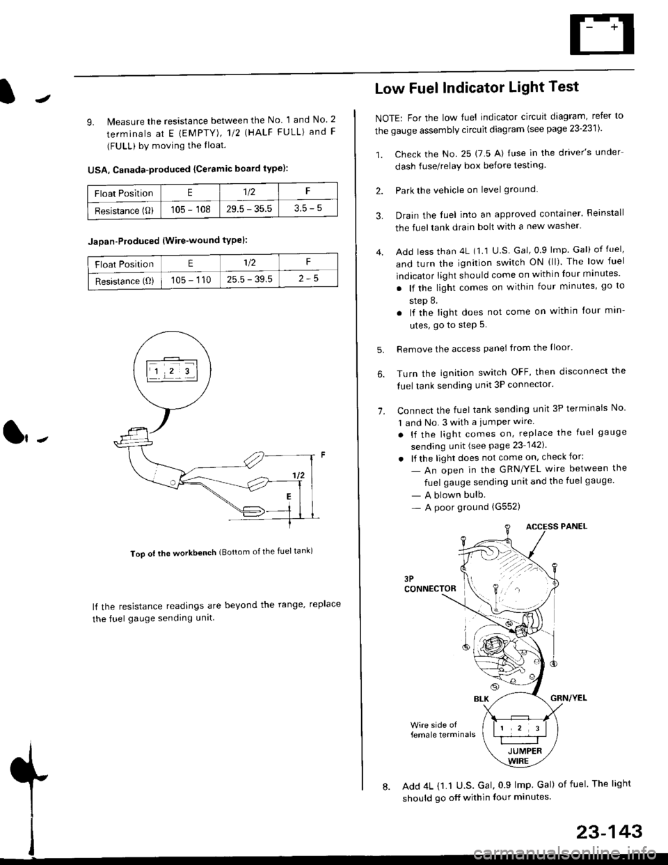
9. lMeasure the resistance between the No 1 and No. 2
terminals at E {EMPTY), 112 \HALF FULL) and F
(FULL) by moving the lloat.
USA, Canada-produced {Ceramic board type):
Too ot lhe workbench (Bottom of the fuel tank)
ll the resistance readings are beyond the range. replace
the fuel gauge sending unit
Float PositionE1t2F
Resistance (0)105 - 10829.5 - 35.53.5-5
Jaoan-Ploduced (Wire-wound typel:
Float PositionE1/2F
Resistance (O)105 - 11025.5 - 39.5
Low Fuel Indicator Light Test
NOTE: For the low fuel indicator circuit diagram, refer to
the gauge assembly circuit diagram (see page 23'2311.
1. Check the No. 25 (7 5 A) luse in the driver's under
dash fuse/relay box before testing
2. Park the vehicle on level ground.
3.
4.
Drain the luel into an approved container. Reinstall
the fueltank drain bolt with a new washer.
Add less than 4L (1 1 U.S Gal, 0.9 lmp Gal) of fuel,
and turn the ignition switch ON (ll). The low fuel
indicator light should come on within four minutes'
. lf the light comes on within four minutes, go to
step 8.
. lf the light does not come on within four min-
utes, go to step 5.
Remove the access panel lrom the Iloor'
Turn the ignition switch OFF, then disconnect the
fuel tank sending unit 3P connector.
Connect the fuel tank sending unit 3P terminals No'
1 and No. 3 with a jumPer wire
. lf the light comes on, replace the fuel gauge
sending unit (see Page 23 1421
. lf the light does not come on, check for:
- An open in the GRN/YEL wire between the
fuel gauge sending unit and the fuel gauge
- A blown bulb.- A poor ground (G552)
6.
1.
female terminals
8. Add 4L {1.1 U.S. Gal, 0 9 lmp Gal) of fuel The light
should go off within four minutes.
23-143
Page 1618 of 2189
Interlock System
Park Pin Switch Test
1, Remove the front console (see section 2Ol.
Disconnect the 4P connector from the park pinswitch.
Check for continuity between the No. 3 and No. 4terminals with:- the shift lever any position other than E, or- the push button pushed in E.There should be continuity.
Check for continuity between the No. 3 and No. 4terminals with the shift lever in E and the push but-ton released. There should be no continuiw. lf nec-essary, replace the park pin switch.
NOTE: Park pin switch 4p connector No. 1 and No.2terminals are lor Ay'T gear position console light.refer to the circuit diagram on page 23-1S0.
23-14A
Page 1623 of 2189

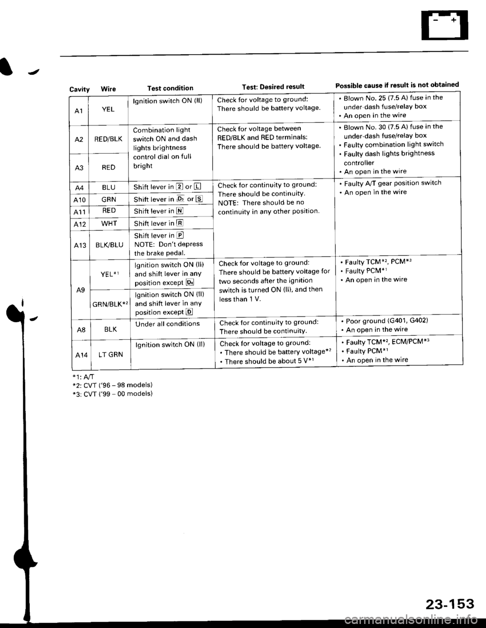
Test conditionTest: Desired resultPossible cause it result is not obtainedCavity
AIYEL
lgnition switch ON (ll)Check for voltage to ground:
There should be banerY voltage.
. Blown No.25 (7.5 A) fuse in the
under dash fuse/relay box
. An open in the wire
A2RED/BLK
Combination light
switch ON and dash
lights brightness
control dial on full
bright
Check for voltage between
RED/BLK and RED terminals:
There should be batterY voltage.
Blown No. 30 {7.5 A) fuse in the
under-dash tuse/relay box
Faulty combination light switch
Faulty dash lights brightness
controller
An open in the wireA3RED
BLUShift lever in P or ICheck for continuity to ground:
There should be continuitY
NOTE: There should be no
continuity in anY other Position.
. Faulty A/T gear Position switch
. An open in the wire
A10GRNShift lever in E or E
A11REDShift lever in E
412WHTShift lever in E
A13BLK/BLU
Shift lever in E
NOTE: Don't depress
the brake pedal.
A9
YEL+ ]lgnition switch ON (ll)
and shift lever in any
position except Pi
Check for voltage to ground:
There should be battery voltage for
two seconds after the ignition
switch is turned ON (ll), and then
less than 'l V.
Faulty TCM*'�, PCM*3
Faulty PCM*r
An open in the wire
GRN/err*'
lgnition switch ON {ll)
and shift lever in anY
position except E
A8BLKUnder all conditionsCheck for continuitv to ground:
There should be continuitY.
. Poor ground (G401, G402)
. An open in the wire
414LT GRN
lgnition switch ON (ll)Check for voltage to ground:
. There should be baftery voltage*'�
. There should be about 5 V*r
Faulty TCM*'�, ECM/PCM*'
Faulty PCM*1
An open in the wire
*2: CVT ('96 - 98 models)*3r CVT ('99 - 00 modelsl
23-153
Page 1624 of 2189
A/T Gear Position Indicator
A/T Gear Position Switch Test
1. Remove the front console (see section 2O).
2. Disconnect the 14P connector from the A/T gear position switch.
3. Check for continuity between the terminals in each switch position according to the table.
' Move the shift lever back and forth without pushing the shift lever at each switch position, and check for continuitywithin the range of free play of the shift lever.' lf there is no continuity within the range of free play, adjust the position of the switch as described on the nextpage.
Terminal side of male terminals
A/T Gear Position Switch
+ 1 : With cruise controlsystem
23-154
Eack - upLight SwitchNeutralPosition Switch