Page 1323 of 2189
Exterior
Component Location Index
NOTE: Refer to the Civic BodV Repair Manual, '1996 Model Series, P/N.6150330,forthe hood, trunk lid and hatch removal.
2Dl30llDl
LICENSE PLATETRIM TRUNK LIDROOF MOLOINGReplacement,
SIDE WINDOWMOLDINGSReplacement,page 20-102Replacement,page 20-100Adjustment, page 20-97Tolsion Bar Removal,page 20-10220 99
HOODAdiustment, page 20 96Hood Edge protector
Replacement, page 20 99
TRUNK LIDWEATHERSTRIPReplacement,page 20-100
REAR BUMPERReplacement,page 2O-95
SILL PANELReplacement, page 20 105
REAR AIR OUTLETReplacement,page 20-106
FUEL PIPEPROTEfiORReplacement,page 20-106
FENDERWELL TRIMReplacement, page 20-106
Replacement,page 20-106
3D:
HATCH
HATCHAdjustment,page 20-98
WEATHERSTRIP
20-93
Page 1327 of 2189
Trunk Lid
Adjustment
NOTE; Before adjusting the trunk lid, loosen each bolt slightly.
1. Adjust the trunk lid hinges right and left, as well as fore and aft, by using the elongated holes'
2. Turn the trunk lid edge cushions, as necessary, to make the trunk lid fit flush with the body at the rear and side edges.
3. Adiust the fit between the trunk lid and the trunk lid opening by moving the striker'
4. After adjustment, tighten each bolt securely
TRUNK LIO EDGE
CUSHION
TRUNK LID
NOTE: Take care notto hit the rear windowwhen loosening thebolts.
NOTE: Move the striker right or left until it's centered in
the trunk lid latch as shown.
TRUNK LIO
9.8 N.m {1.0 kgf.m,7 .2lbl.ltlSTRIKER
20-97
Page 1331 of 2189
Hatch Spoiler
Removal
NOTE: Take care not to scratch the hatch and body
1. Remove the hatch upper trim (see page 20-63)
2. Remove the nuts, and detach the clip, then lift the
hatch spoiler uP.
a: Nut locations, 4
1 2lbt.ftl _ j/
GROMMET
HIGH MOUNT BRAKELIGHT CONNECTOR
Disconnect the high mount brake light connector and
rear window washer tube, then remove the hatch
spoiler.
------,*;)
4. lf necessary. remove the spoiler trim from the spoiler
frame.
NOTE: The hatch spoiler trim for Canada produced
cars cannot be disassembled.
>: Clip locations
A>,4
>: Scr€w
5. Installation is the reverse of the removal procedure'
NOTEi
. lf necessary, replace any damaged clips.
a Make sure the connector and washer tube are
connected ProPerlY.
20-101
Page 1332 of 2189
Side Window MoldingsRoof Molding
Replacement
CAUTION: Put on glovos to protect your hands.
NOTE:
. Take care not to scratch the body
. Remove the screw, and pull th€ side window molding
by hand.
>: Clip locationsA>,13
Installation is the reverse of the removal procedure.
NOTE: lf necessary, replace any damaged clips.
1l
)
A
>: Screw locations,
*@
MOLOING
\
20-102
Replacement
CAUTION: When prying with a flat-tip screwdriver, wrap
it with protestive taps to prevent damage, and use pro-
toctiv€ tape on the body.
NOTE: Take care not to scratch the bodv.
WINDSHIELOMOLDING
Installation is the reverse of the removal procedure.
NOTE:
. Take care not to damage the windshield molding.. Make sure the roof molding is installed securely.
K
PINlBody side)
I
)
Page 1337 of 2189
Opener Cable/Opener and Latch/Wiper and Washer
Component Location Index
2Dt3DItD'
y"Tl,"nll,ib?*'r.* o*t"
Replacement, Page 20_1 13
Adiustment, Page 20'1 17
WINDSHIELDWASHER NOZZLESAdjustment, Page 20_1 17
HOOD LATCH
{see page 20-110)
REAR WINDOW WIPER
ARM and MOTORReplacement, Page 20-1 15
Adjustment, page 20 117
LOCK CYLINDER(see page 20 113)
LOCK CYLINDER
TRUNK LIO LATCH
{see page 20 112)
FUEL LID OPENERCABLE(see page 20-108i
LID OPENERCABLE(see page 20 108)
LID/FUELLID OPENER(see page 20 111)
RELEASE HANDLE(see page 20-110)
3D:
REAR WINDOWWASHER NOZZLEAdiustment, page 20-1 17
REAR WINDOWWASHER TUBE(see page 20-116)
HATCH OPENERCABLE(see page 20 110)
WASHER RESERVOIRReplacement, Page 20-1 15
HATCH/FUEL LID OPENER(see page 20 1'11)
FUEL LID OPENERCABLE(see page 20 110)
(see page 20 111)
20-107
Page 1345 of 2189

Rear Window Wiper
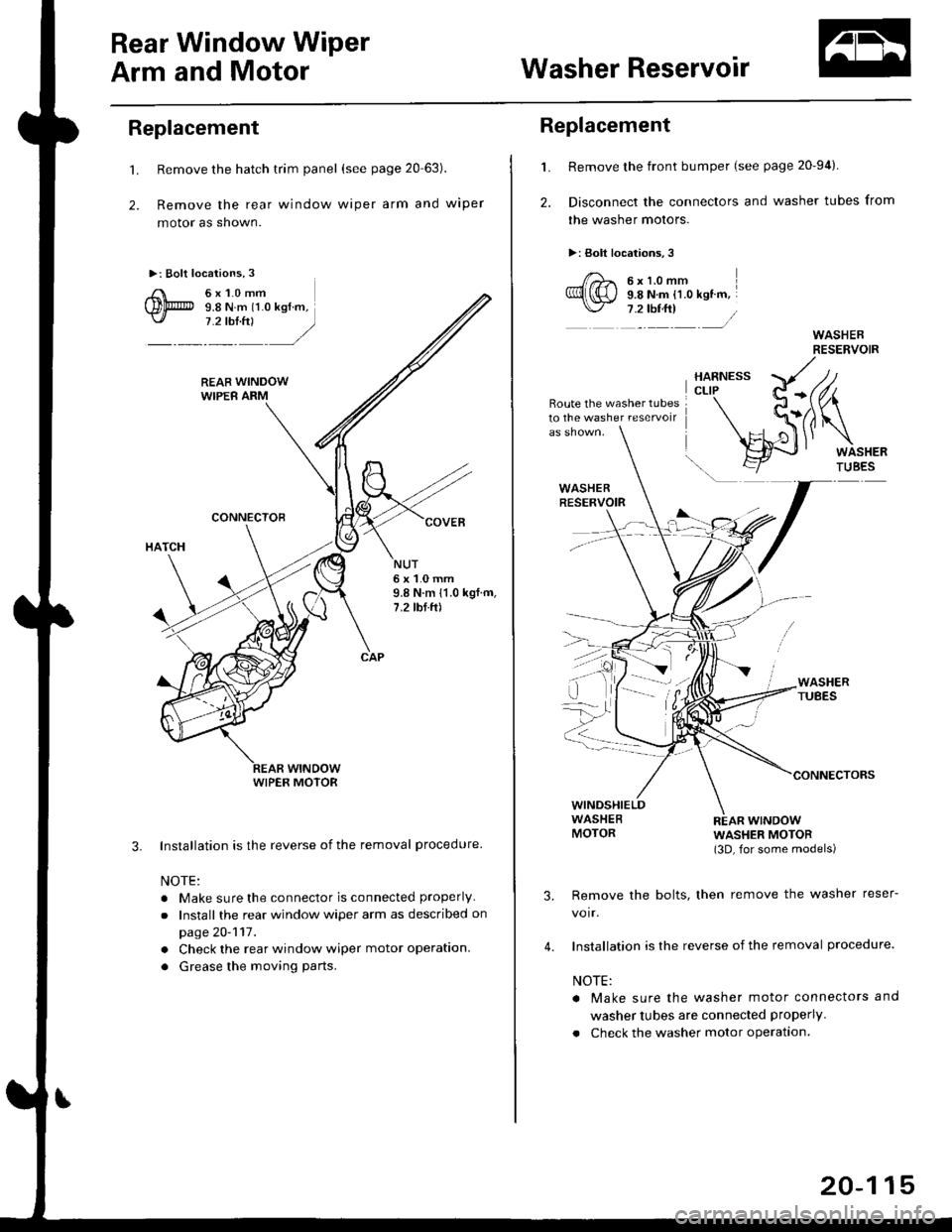
Arm and MotorWasher Reservoir
Replacement
't.
2.
Remove the hatch trim panel (see page 20 63).
Remove the rear window wiper arm and wiper
motor as shown.
Installation is the reverse of the removal procedure
NOTE:
. Make sure the connector is connected properly
.Install the rear window wiper arm as described on
page 20-117.
. Check the rear window wiper motor operation.
. Grease the moving parts.
3.
NUT6x1.0mm9.8 N.m 11.0 kgf.m,7.2 tbf.ft)
WIPER MOTOR
L
2.
Replacement
Remove the front bumper (see page 20-94).
Disconnect the connectors and washer tubes from
the washer motors.
>: Bolt locations,3
/)^ 6xt.omm
Ql(S) s.e ru.- tt.o ret '".\./ 7 .2 tbf.ft) /
Route the washer tubes10 the washe. reservoir
wtNDowWASHER MOTOR(3D, for some models)
Remove the bolts, then remove the washer reser-
voir.
Installation is the reverse of the removal procedure.
NOTE:
a Make sure the washer motor connectors and
washer tubes are connected properly.
. Check the washer motor operation.
3.
4.
20-115
Page 1346 of 2189

Washer Tube
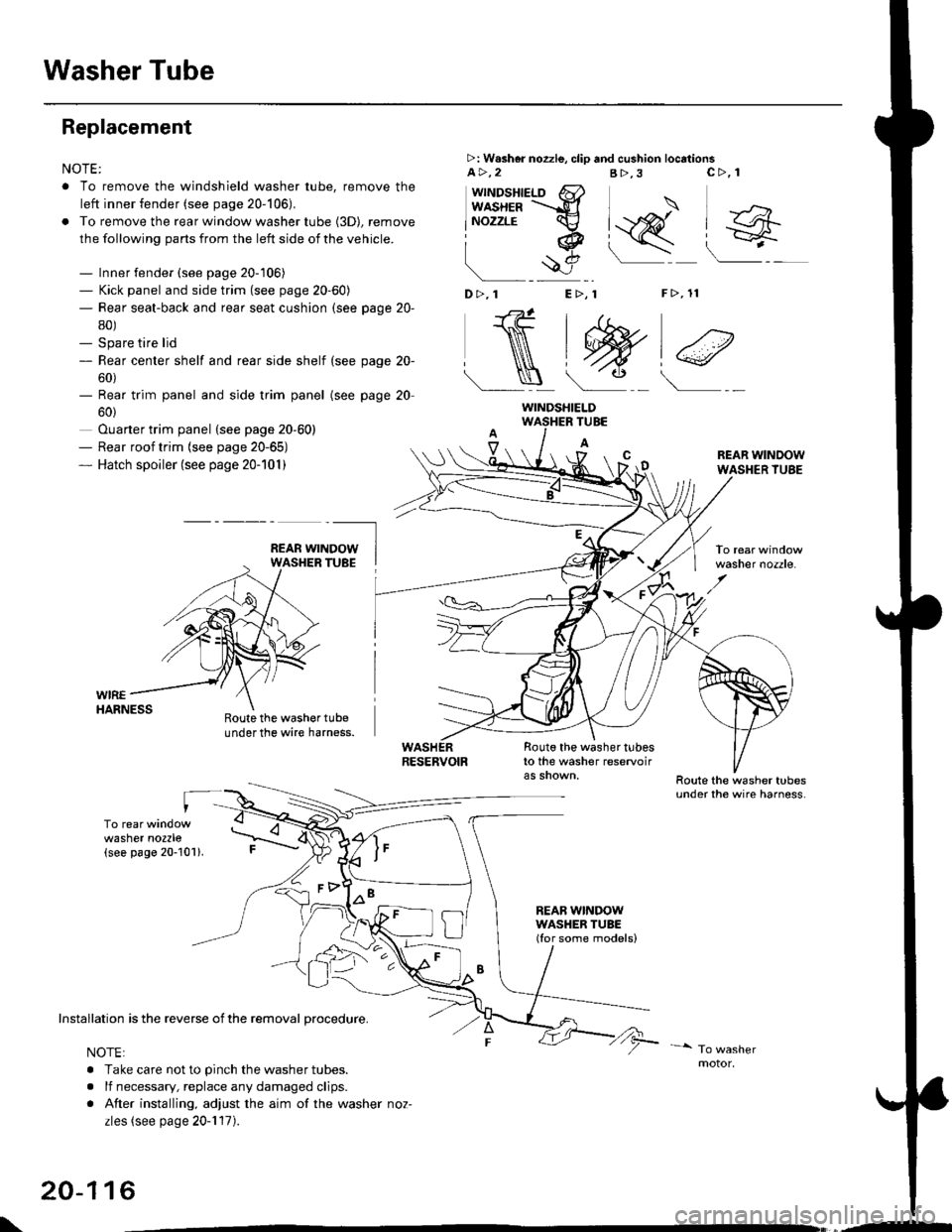
Replacement
NOTE:
. To remove the windshield washer tube, remove the
left inner fender (see page 20-106),
. To remove the rear window washer tube {3D), remove
the following parts from the left side of the vehicle.
- Inner fender (see page 20-106)- Kick panel and side trim (see page 20-60)- Rear seat-back and rear seat cushion (see page 20-
80)- Spare tire lid- Rear center shelf and rear side shelf (see page 20-
60)- Rear trim panel and side trim panel
60)
Ouarter trim panel (see page 20-60)- Rear roof trim {see page 20-65)- Hatch spoiler (see page 20-101)
(see page 20
WIREHARNESS
>: W.sher nozzle, clip and cushion locationsa>,2B>,3
"J>)
[q@"
F>, 11
c>, 1
wttrtosnteLo 6}usxea =-d
lNozzrE cv
iq
!$e
D>,1 E>, 1
NtW)€
Roote the washer tubeunder the wire harness.
TUBE
A
Route the washer tubesto the washer reservoir
REAB WINDOWWASHER TUBE(Ior some models)
REAR WINDOWWASHER TUBE
washer nozzle.
washer nozzle(see page 20-101).
oo\
Installation is the reverse of the removal procedure.
NOTE:
. Take care not to pinch the washer tubes.
. lf necessary, replace any damaged clips.
. After installing, adjust the aim of the washer noz-
zles (see page 20-117).
20-116
WINDSHIELD
\,--
Page 1347 of 2189

Wiper Arms/Washer Nozzles
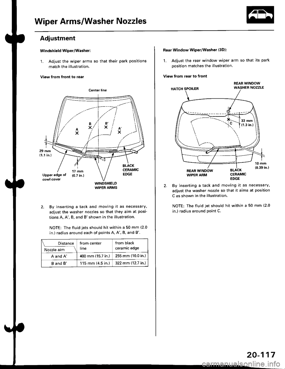
Adjustment
Windshield wiper/Washer:
1. Adjust the wiper arms so that their park positions
match the illustration.
View trom tront to rear
WINDSHIELDWIPER ARMS
2. By inserting a tack and moving it as necessary,
adjust the washer nozzles so that they aim at posi-
tions A, A', B, and B'shown in the illustration.
NOTE: The fiuid jets should hit within a 50 mm (2 0
in.) radius around each of points A, A', B, and B'.
.// \
A'x..
-.4
,'lxiAx
Distance
M;r.";-lll
from center
lrne
from black
ceramrc eoge
A and A'400 mm (15.7 in.)255 mm (10.0 in.)
B and B'115 mm (4.5 in.)322 mm \12.7 in.)
Rear Window wiper/Washer (3Dl:
1. Adjust the rear window wiper arm so that its park
position matches the illustration.
View trom raar to front
CERAMICEDGE
By inserting a tack and moving it as necessary,
adjust the washer nozzle so that it aims at position
C as shown in the illustration.
NOTE: The fluid jet should hit within a 50 mm (2.0
in,) radius around point C.
REAR WINOOWWIPER ARM
r-
---..J_.__11,:l
20-117