Page 1590 of 2189

Charging System
Alternator Replacement
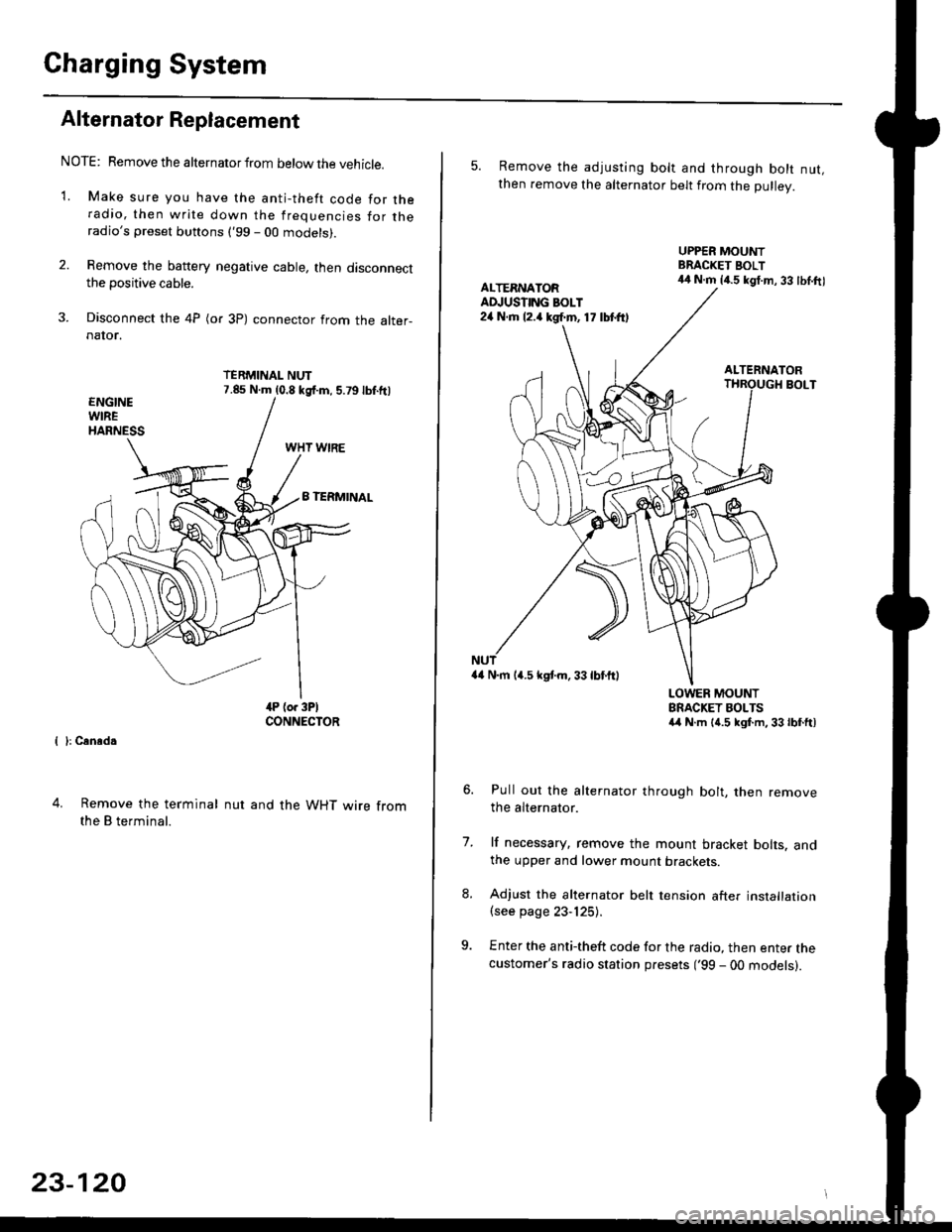
NOTE: Remove the alternator from below the vehicle.
'1. Make sure you have the anti-theft code for theradio, then write down the frequencies for theradio's preset buttons ('99 - 00 models).
2. Remove the battery negative cable, then disconnectthe positive cable.
3. Disconnect the 4P (or 3P) connector from the alter-naIor.
TERMINAL NUT7.85 N.m (0.8 kgf.m, 5.79lbf.ftl
{ }: Cansd.
4. Remove the terminal
the B terminal.
nut and the WHT wire from
23-120
5. Remove the adjusting bolt and through bolt nut,then remove the alternator belt from the Dullev.
UPPER MOUNTBRACKET BOLT44 N.m 14.5 kgt.m, 33 lbl.ftlALTERNATORAD.'USTING BOLT24 N.rh l2.a kgf.m, 17 lbtft)
ALTERNATORBOLT
a4 N.m 14.5 kstm.33lbf'ftl
LOWER MOUNTBRACKET BOLTSa4 N.m l{.5 kgf.m,33lbfft)
Pull out the alternator through bolt, then removethe alternator.
lf necessary, remove the mount bracket bolts. andthe upper and lower mount brackets
Adjust the alternator belt tension after installation(see page 23-125).
Enter the anti-theft code for the radio, then enter thecustomer's radio station presets ('99 - 00 models).
7.
Page 1592 of 2189

Charging System
Rectifier Removal (cont'd)
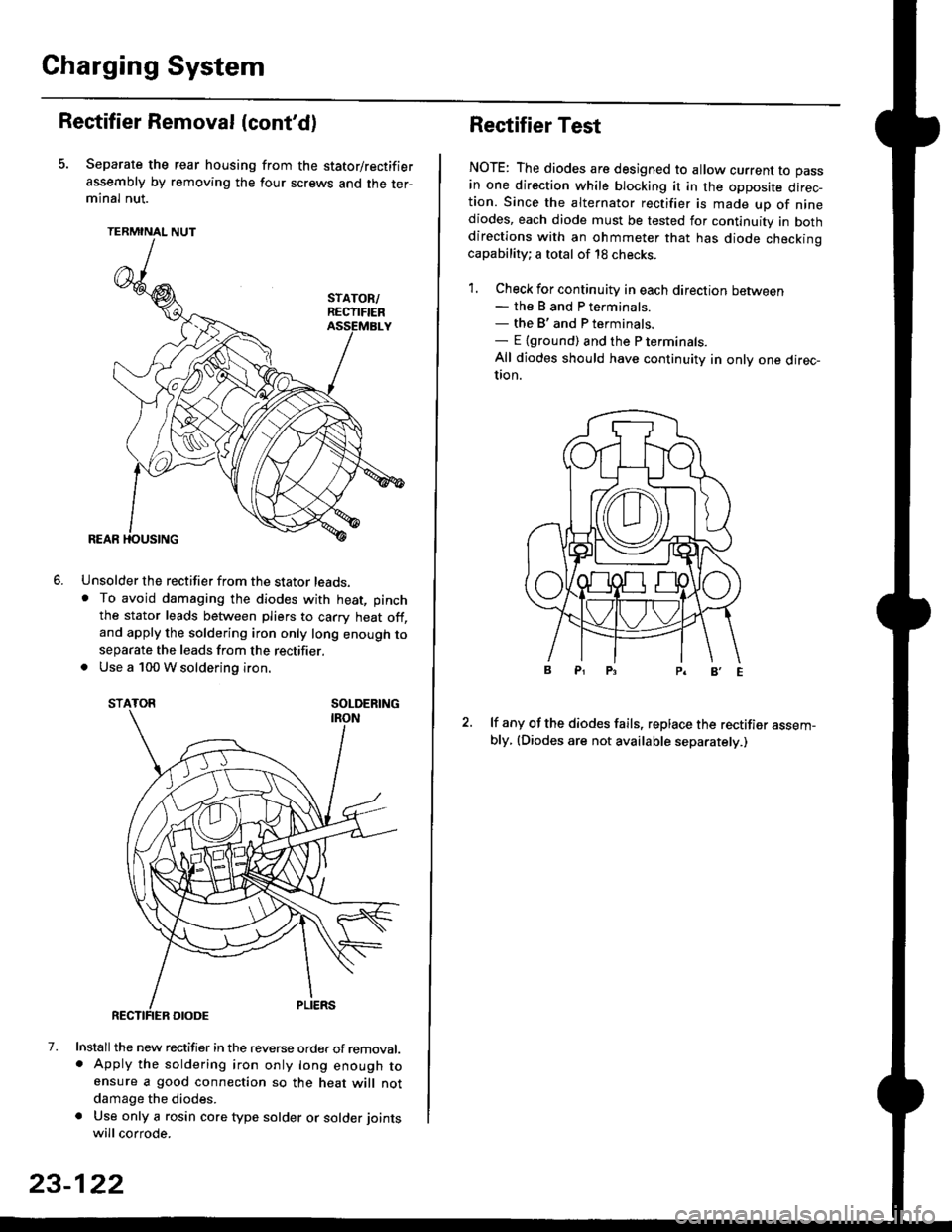
Separate the rear housing from the stator/rectifier
assembly by removing the four screws and the ter-minal nut.
TERMINAL NUT
Unsolder the rectifier from the stator leads,. To avoid damaging the diodes with heat, pinch
the stator leads between pliers to carry heat off,and apply the soldering iron only long enough toseparate the leads from the rectifier.. Use a 100 W soldering iron.
STATOR SOLDERING
7. Install the new rectifier in the reverse order of removal.. Apply the soldering iron only long enough toensure a good connection so the heat will notdamage the diodes.
a Use only a rosin core type solder or solder joints
will corrode.
6.
SOLDERING
23-122
Rectifier Test
NOTE: The diodes are designed to allow current to pass
in one direction while blocking it in the opposite direc-tion. Since the alternator rectifier is made up of ninediodes, each diode must be tested for continuity in bothdirections with an ohmmeter that has diode checkinocapability; a total of 18 checks.
1. Check for continuity in each direction between- the B and P terminals.- the B'and P terminals.- E {ground) and the P terminals.
All diodes should have continuity in only one direc-UOn.
lf any of the diodes fails, replace the rectifier assem-bly, (Diodes are not available separately.)
Page 1601 of 2189
IJNOER,DASHFUSE/RELAY BOX
GAUGELIGHTS
l3wx4 l
CHARGINGSYSTEMLIGHT0.4w)
Gircuit Diagram
UNDEN HOOD FUSE/RELAY BOXIJ
N0.30 (7.54)FUSE
f7
I
tlRED/BLK BEO/BLK
l"l"8LK BLU
IJ
l'"^*
I
t-
G401G402
__l
tE2
IFED/BLU
CRUISECONTROTUNIT
fl ,,1:
tH
I c12
IFFD
VDASH LIGHTSBRIGHTNESSCONTROLLEF
l"'WHT/BLU
vALTERNATOR
(With shifi-up indicatd lighl)(wi1h cruise conlrcl system)
Page 1607 of 2189
JBulb Locations {Without Tachometer)
TRUNK INDICATORLIGHT {1.i1W}
.4 Wl
CHARGING SYSTEM LIGHT 11,4 W}
LTGHT (1.4 W)GAUGE LIGHT
SEAT BELTREMINDER LIGHT (1.4 WI
LOW ENGINE OIL PRESSUBE
INDICATOB LIGHT (1.4 WI
LOW FUEL INDICATORLrGl{T (3 W)
RIGHT TURN SIGNALINOICATOR LIGHT
(1.1Wt
GAUGE LIGHTS {3 WI
WASHER LEVELINDICATOR LIGHT{1.4 W} lcanad.l
HIGH BEAMINDICATOR LIGHTMALFUNCTIONINDICATORLAMP (MIL)
BULB {1.4 WI
{1.ilW)
LEFT TURN SIGNALINDICATOR LIGHT {1.4 WI
A/T GEAR POSITIONINDICATOR (1.12 x 6)(On the printed
circuit board)
sRs TND|CATOR 11.4 W)
{On the Drinted circuit board}
aBs tNDtcAToR t1.4 W)(On the printed circuit board)(3.{ Wt
o/ o \7 o
23-137
Page 1817 of 2189

Contents
How to Use This Manual ICircuit Schematics (see Circuit Index)Fuse/Relaylnformation 6Ground-to-Componentslndex 6-6ComponentLocationPhotooraohs 201Conriector Views 202
Circuit Index
Accessory power socket 155Air conditionerAir delivery'96198 models 61'99-'00 models 61-2Blower controls'96198 models 60'99100 models 60-1Compressor controls 62Fans 63Anti-lock brake system (ABS) 44A/T gear position indicatorCVT 89All except CVT 89-1Automatic transmission controlsAll '96-'98 models except CVT and GX 39All '99100 models except CVT 39-8All GX models 39-8'96-'�98 CVT 39-4'99100 cw 39-12Back-up lightsCoupe and Sedan 110Hatchback l'10-1Brake lightsAll Coupes and'96-'98 Sedans 110-15'99-'00 Sedans 110-16Hatchback 110-17Brake system indicator light'96198 models 7'1'99100 models 71-1Ceiling light 114-3Charging system 22Condenser fan 63Console lights 114Cruise control 34Dash lights 114Daytime running lights 110- 13Engine coolant temperature gauge 81-1Fog lights 110-10Front parking lights 110-2Fuel gauge 81-1Fuse/relay boxUnder-dash 6Under-hood 6-4Underhood ABS 6-3Gauges 81Ground distribution 14Ground-to-Componentslndex 6-6Hazard warning lightsAll except '99100 Sedans 110-6'99100 Sedans 110-8Headlights 110-12Headlight switch 100Heater - See Air ConditionerHorn'96197 models 40'98 model 40-1'99100 models 40-2lgnition key reminder 73lgnition systemAll '96198 models except Dl685 20All '99100 models except D16Y5 with Mn 2O-2All D1685 engines 20-2'99-'00 D 16Y5 with M/T 20
lndicators 80Integrated control unit 70lnterlock systemAll except'96J98 CVT 138'96198CVT 138-1License plate lightsAll Coupes and '96-'98 Sedans I l0-3'99100 Sedans 1 10-4Hatchback 110-5Low fuel indicator light 74Moonrool'96197 models |22'98-'00 models 122-1Odometer 81Oil pressure indicator light 80-3Power distributionBattery to ignition switch, fuses, and relaysFuses to relays and components 10-2Power door locksAll models without keyless entry 130'96-'98 models with keyless entry 130-2'99100 models with keyless entry 130-12Power mirrorsWithout detogger 141With defogger '141-2
Power windows 120Programmed fuel injection system (PGNr-Fl)All '96-98 models except D1685 23All '99-'00 models except D16Y5with M/T and D1685 24All D1685 engines 25'99100 D16Y5 with M/T 23Radiator fan 63Rear window defogger'96-,98 models 64'99100 models 64-1Seat belt reminder 73Security system'96.'98 USA HX, LX, EX 133'96-'98 Canada EX, Si 133'99TOO USA HX, LX, EX, DX.V Si 133-4'99100 Canada EX, Si 133-4All CX and DX models 133-8Speedometer 81Starting systemA./T (All except Dl685) 21A"/r (D16Bs) 21-1Manualtransmission 21-2Slereo sound system 150Supplemental rastraint system (SRS) 47Tachometer 81TailliqhtsAllboupes and'96-'98 Sedans 110-3'99100 Sedans 1 10-4Hatchback 110-5Trunk light 114-3Turn signal lightsAll except'99100 Sedans 110-6'99-'00 Sedans 1 10-8Vehicle speed sensor (VSS) 33Wiper/washerFront 91Rear 92
10
Page 1878 of 2189
Charging System
See PowerDistribution,pag6 10.
UNDER-HOODFUSE/RELAYBOX
FUSE 15ALT€IIIAIONsP SEII|SOF7.5A
I
t
USA
' BLKAVHTBLKI"VI/HT
-)l,------J
vtEw 50
See PowerDistribution,page 10-5.
* = 96-98rAllmodelsexcept 01685'99 '00: D16Y5 withi.4/T** = '96'�98: All models'99r00: D16Y5 witht\4/T, D1685
BATTERY
ALTERNATOR
See PowerDiskibution,page 10.
FUSE 41BATTEFY804
T101
L-----
ELECTFICALLOADDETECTOR(ELO) UNIT
'l
;l
:l
:l;l
:l
tl,l
:l
:l
G1!
- -I POWER-I -. ^ "'.1 , I rnlrn or
(.A1e)Y '('� C17)c2[ : cs
i ELD unit input i ietCrHe! ' ! coNrRoLI I MODULEI Art€rnator : lllerlato.r I (PCM or
i controrsrsnar i t",fl?il"' a:"^y]L- ----,1- - - - J Pq_oro 3'
*. B,'"',1; :.i
i:1E15_'_
_. i
GFN/FED
r i6
GFN/RED
A30
f D16)WHT/REO*Fi
See Ground IDistribution, Ipage 14-5. I
YT
L]
' ""- PHA|O
,.^;?f, :('c;3)T BLXYEL
I i 'r", ".o II'HT/ ll ' U,zscnrl :-' oi .l
, L : (c'r9ill-_- 'c11" 2)u
l9nitionrnput
LOaO
Ground ourpur
22
Page 1887 of 2189
: , See ly'C ' See, See ' Compressor : Charging' Fans : Controls ; System
'YI Y:Y
:l: ll:[
il: l:l
i*"1 i "*"."1 : o"",".o1
, r | : -^*l
ili I i Ii. *, I i rrz.l, ; ot. I'.--..--r-
/i**fffi'* I r,rcffi"oro, i e.St*I ; cornrd ' clulcfi rday ' nput
| .-,---;---l COntrOl
\'
\;t ' Altsrnqtor! Nc Altemator : conrol
/, u.1;lf* roqrsr rnpd FRfrgd ; tSJ",
&rrr:rr
SeeCharornoSystein - :
Y:
!i
u".o I i
i:
o,. .!, iPOWERTRAIN
l*.]["n i 13'"',1+?3.': I MODULE; | (PcM or EcM)
i lw,t?'"
Altornstor ; Iconrol i I
$:--lJ
"''I
',n,-
I
I
See VehicleSpeed Sensorryss)
*[
".,^."
!
I
t
See NCCompressorControls
.r_l
See Charging Sysetm
(cont'd)
23-7
Page 1900 of 2189

i--I,*.;----l
I I ffl* s€€ Pow€' I
!---h=js:q-l
r'1ltii*",
! il"Jiisa"
;ll
i-[*-*"".""--l
! @ffi[+[ffI. !
! Ir6rer i
L--L-,sr@lc5Y
UNDER.DASHFUSE/RELAYBOXPHO|O 58
GAUGEASSEMBLY
;------- USA -------,
see ly'c i S"" :Compressor , See Charging ;Controts , Fans System , POWERTRAIN-
li*t*rr,, ".o^.of, i """f """,tr' i tff'$fit!
Tl,!,
"0o -;;l
i ;;l ^*l i
n"""j.F,rH;
Irs I A17 A :A2oA moA :
,'-----ri;)---7ol------T-;;l----,il--i-----'r,' r',lrr- di-ritror lvc "orip-E""or : Fa; ;;iror eldiinit : II clutci relay conlrcl InPd I\tri---"---i t!9--. i-;ter";--I i{r,*+-i 1s"'*.'lr I t'lc : EGR control : : Atternator I A[emator ]'. I KS : requ6st ; solenoid ; VSS ' control , FR Ia , inDut : inout , \iave control , inpul , sional ' sianal I, , (Ks) i i*"1 , (Esor, _jt,__.j-_JgL-.j__ ,^:_j3------- --- --- -- -.4- -- -- -,1-- - -
i"fiti".,ff:l i"111 iffilifili"F"l
i*l i + i I i
"+
i-"1 :''"1T'See LiC , I ' See vehicle t--'---'-'
ComOressor , 2 ^C142 : SpeedContiofs | | PHoro124 i Sensor
i ft> i :"::l
' ".o
|
",o,o,,0
i lisi: 3i&S**n,"n
i Lti-t i i rh;ry,'s;3+r"" i
: I ""n,".*l iiltll lS'"",.?^8"'$lli'til ""n'"'*! iil-il]J5ff#f."ruuu
i ll.,*'o.* ! *o,o,no i i l'.lT- seecround
: FflSI8$" i Btr"lifiiJ}': i i *i[ Bi,i"EL'""
; f lJffi""' !**;' i i":-lei'u!,7,,"
ws{u'
(cont'd)
24-5