2000 HONDA CIVIC charging
[x] Cancel search: chargingPage 1451 of 2189
Recovery
Use only service equipment that is U.L.-listed and is cer-
tified to meet the requirements of SAE J2210 to remove
HFC-134a (R-134a) from the air conditioner system
CAUTION: Exposure to air conditioner relrigerant and
lubricant vapor or mist can illitate eyes, noss and
throat. Avoid breathing the ail conditioner refrigerant
and lubricant vapor or mist.
lf accidental system discharge occurs, ventilate work
area before resuming service.
R-134a service equipment or vehicle air conditioner sys-
tems should not be pressure tested or leak tested with
compressed air.
!@@ some mixtures ot air and R'13'[a havo been
strown to be combustiblg at elevated pressures and Gan
resuh in fire or explosion causing iniury or property dam-
age, Never use compressed air to pressure test R-134a
service equipment or vehicle air conditioner systems.
Additional health and safetv information may be obtained
from the refrigerant and lubricant manufacturers.
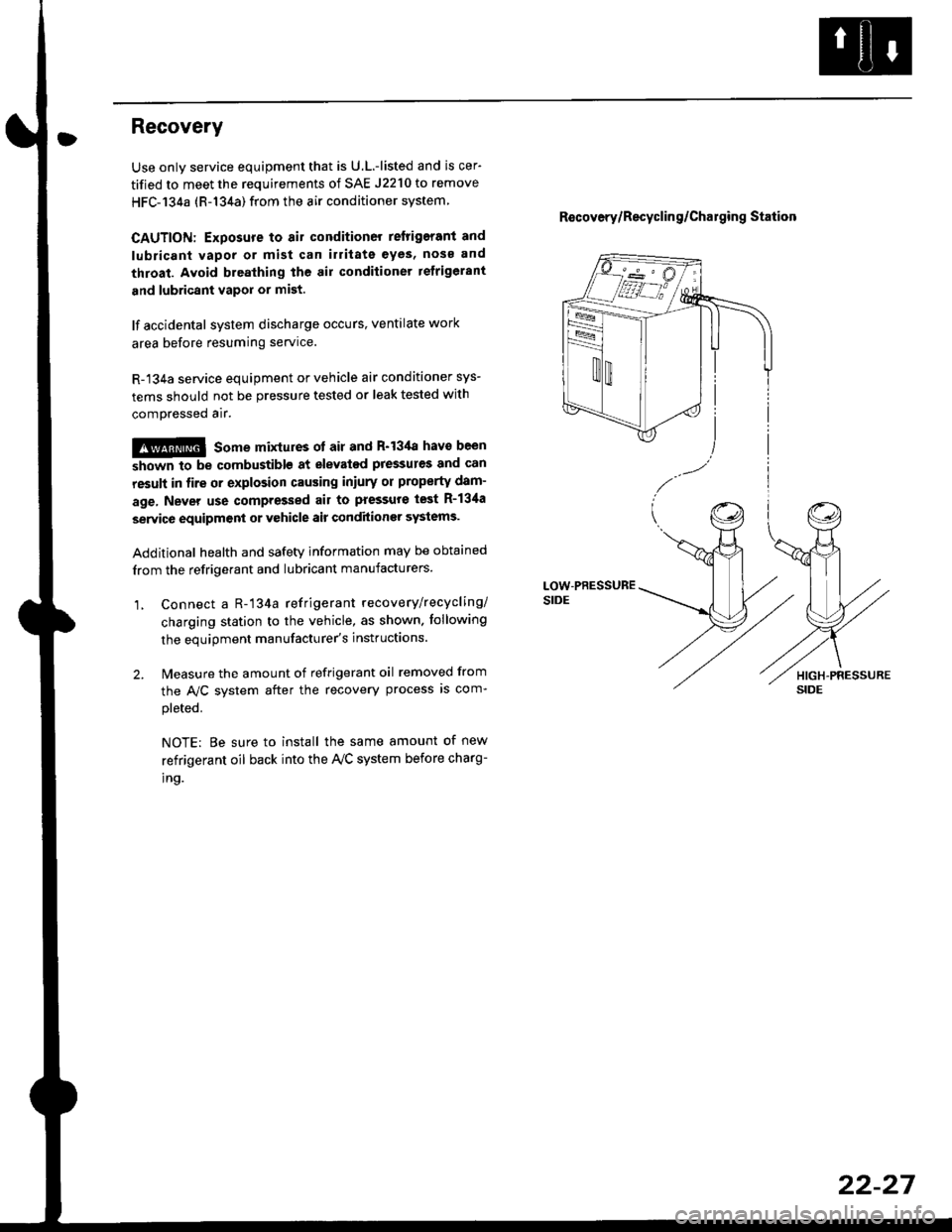
1, Connect a R-'134a refrigerant recove rylrecycling/
charging station to the vehicle, as shown. tollowing
the equipment manufacturer's instluctions.
2. Measure the amount of refrigerant oil removed from
the A/C svstem after the recovery process is com-
pleted.
NOTE: Be sure to install the same amount of new
refrigerant oil back into the Iy'C system before charg-
tno.
R€covery/Recyclin g/Cha19ing Station
22-27
Page 1452 of 2189
Evaporator
1.
Replacement
4.
Move the temperature control to "HOl"
'96-98: Slide the temoerature control lever.'99-00: Turn the ignition switch ON (ll), then turn
the temperature contol knob. Turn the ignition
switch off.
Remove the battsry.
Rgcover the refrigerant with a rocovery/recycling/
charging station (see page 22-271.
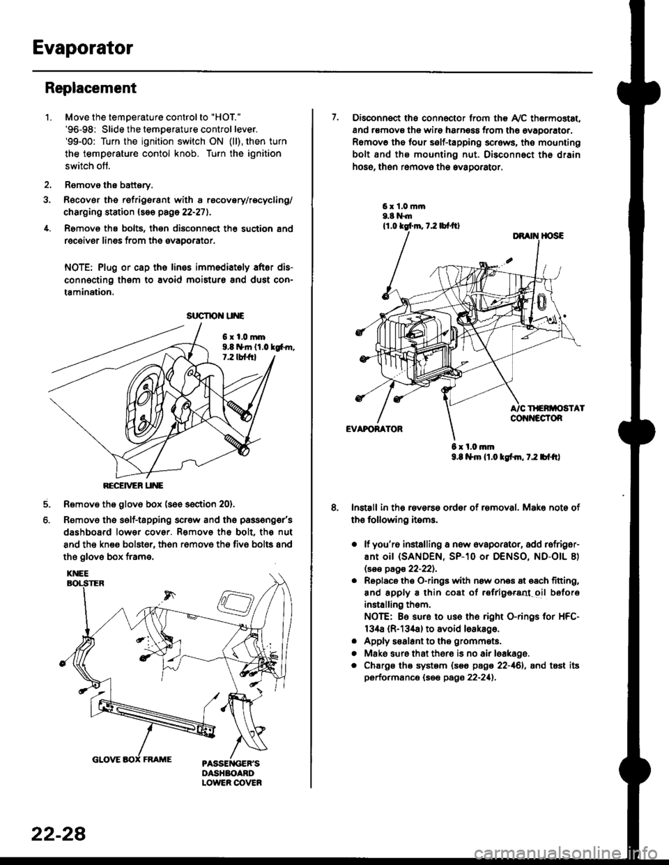
Remove the bolts, then disconnect th6 suction 8nd
receiver lines from th6 evaoorator.
NOTE: Plug or cap the lines imm€diatoly after dis-
connecting them to avoid moisture and dust con-
tamination.
6xl.0mm9.8 n*ln ll.0 tg6m.7.2 lbt frl
RECEiVER UNE
Remove the glov6 box (see section 20).
Removo the self-tapping scr€w and the passeng€r's
dashboard lower cover. Removs the bolt. the nut
8nd the kn€e bolst6r, th6n r6mov6 th6 fiv6 bolts and
the glove box frame.
6.
srrcrrc u E
22-28
7. Disconnect the connector from th€ Ay'C thermostat,
and r€movs the wire harness from the ovaporator.
Remov6 tho four self-tapping screws, tho mounting
bolt and ths mounting nut. Disconnect th€ drain
hose, then remov€ th6 avagorator.
6 x l.0.nm9.8 l$m lt.o ldm, 7.2 bl.tt)
Install in the reverse order of removal. Make note of
th€ following items.
o lf you'r6 installing a new evaporator, add rofriger-
ANt OiI {SANDEN, SP-10 Or DENSO, ND-OIL 8)
lsas page 22-221.
. Replace the O-rings with now ones 8t 68ch titting,
and apply 8 thin coat of r€frlgersd oil before
installing them.
NOTE: Be sure to use the right O-rings for HFC-
134a (R-134a) to avoid loakago.
. Apply s€alant to tha grommets.
. Mske sure that ther€ is no air leakage.
. Chargs ths system {s€€ page 22-161, and tost its
performance (see pags 22-211.
Page 1454 of 2189
Compressor (SANDENI
Replacement
1.lf the compressor is marginally operable, run the
engine at idle speed, and let the air conditioner
work for a few minutes. then shut the engine off.
Disconnect the negative cable from the battery.
Recover the refrigerant with a recovery/recycling/
charging station (see page 22-27l..
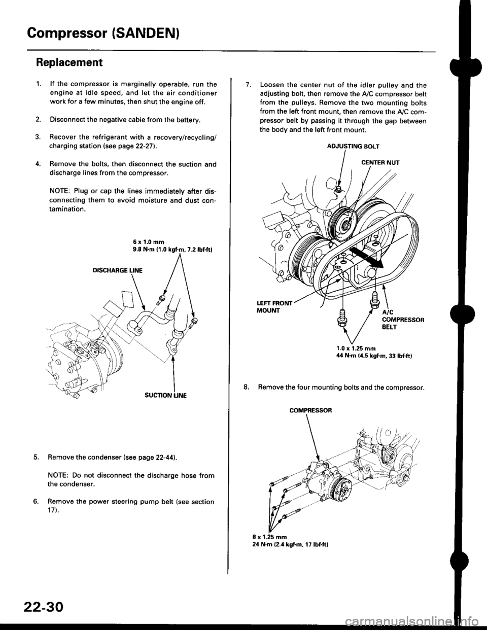
Remove the bolts, then disconnect the suction and
discharge lines from the compressor.
NOTE: Plug or cap the lines immediately after dis-
connecting them to avoid moisture and dust con-
tamination.
6xl.0mm
Remove the condenser (see page 22-44).
NOTE: Do not disconnect the discharge hose from
the condenser.
Remove the power steering pump belt (see section
17 t.
22-30
24 N.m l2.ia kgt.m, 17 lbf.ftl
7. Loosen the center nut of the idler pulley and the
adjusting bolt. then remove the A,/C compressor belt
from the pulleys. Remove the two mounting bolts
from the left front mount, then remove the ly'C com-pressor belt by passing it through the gap befiiveen
the bodv and the left front mount.
ADJUSTING BOLT
1.0 x 1.25 mmaa N.m 14.5 kgf,m, 33 bnft)
8. Remove the four mounting bolts and the compressor.
CENTER NUT
COMPRESSOR
Page 1461 of 2189
Compressor (DENSO)
Replacement
1.lf the compressor is marginally operable, run the
engine at idle speed, and let the air conditioning work
for a few minutes, then shut the engine off
Disconnect the negative cable from the battery'
Recover the refrigerant with a recovery/recycling/
charging station lsee page 22-271
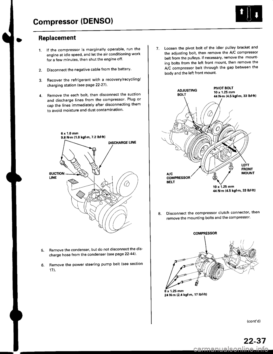
Remove the each bolt, then disconnect the suction
and discharge lines from the compressor' Plug or
cap the lines immediately after disconnecting them
to avoid moisture and dust contaminatlon.
6 x '1.0 mm9.8 N.m (1.0 kgf m,7.2 lbfft)
Remove the condenser, but do not disconnect the dis-
charge hose from the condenser (see page 22-441'
Remove the power steering pump belt (see sectron
17]-.
7. Loosen the pivot bolt of the idler pulley bracket and
the adjusting bolt. then remove the A,/C compressor
belt from the pulleys. lf necessary, remove the mount-
ing bolts from the left front mount. then remove the
fuC compressor belt through the gap between the
bodv and the left front mount.
'10 x 1,25 mm4,0 N.m (,1.5 kgf'm. 33 lbt ftl
Disconnect the compressor clutch connector, then
remove the mounting bolts and the compressor'
PIVOT BOLT10 x 1.25 mm4,1 N.m (4.5 kgt'm,33 lbfft)
COMPRESSOR
24 N.m (2.4 kgf m, 17 lbf ftl
(cont'd)
22-37
Page 1466 of 2189
Compressor (DENSO)
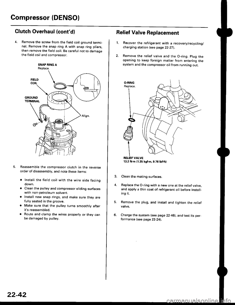
Clutch Overhaul (cont'd)
Remove the screw from the field coil ground termi-nal. Remove the snap ring A with snap ring pliers.
then remove the field coil. Be careful not to damaoethe field coil and compressor.
SNAP NING AReplace.
Reassemble the compressor clutch in the reverseorder of disassembly, and note these rrems:
o Install the field coil with the wire side facingdown.
a Clean the pulley and compressor sliding surfaceswith non-petroleum solvent.. Install new snap rings, and make sure thev arefully seated in the groove.
. Make sure that the pulley turns smoothly afterit's reassembled.
. Route and clamp the wires p.operly or they canbe damaged by pulley.
FIELOcorL
22-42
13.2 N.m 11.35 kgt m,9.76lbtttl
Relief Valve Replacement
L
4.
Recover the refrigerant with a recovery/recycling/charging station {see page 22-27),
Remove the relief valve and the O-ring. plug theopening to keep foreign matter from entering thesystem and the compressor oilfrom running out.
Clean the mating surfaces.
Replace the O-ring with a new one at the relief valve.and apply a thin coat of refrigerant oil before install-ing it.
Remove the plug, and install and tighten the reliefvatve.
Charge the system (see page 22-46), and test its per-formance (see page 22-24),
Page 1468 of 2189
Condenser
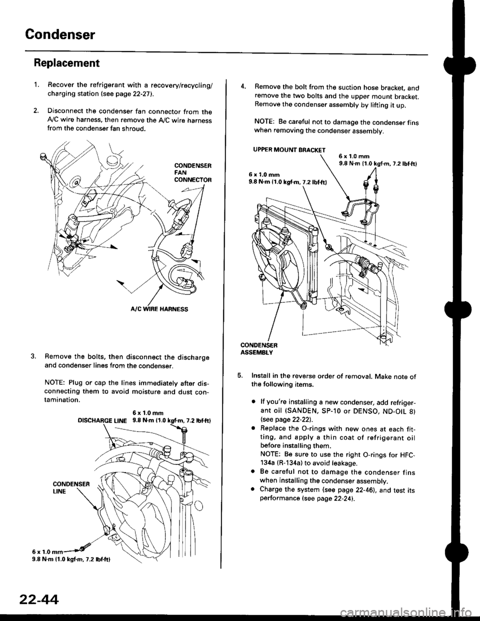
Replacement
1.Recover the refrigerant with a recovery/recycling/
charging station lsee page 22-271.
Disconnect the condenser fan connector from theAy'C wire harness, then remove the A,/C wire harnessfrom the condenser fan shroud.
Remove the bolts, then disconnect the dischargeand condenser lines from the condenser.
NOTE: Plug or cap the lines immediately after dis-connecting them to avoid moisture and dust con-tamination,
6r1.0
6x1.0mmolscHARGE L|NE 9.8 N.m 11.0
9.8 N.m 11.0 kgl.m, 7.2 lbf.ftl
22-44
4. Remove the bolt from the suction hose bracket, andremove the two bolts and the upper mount bracket.Remove the condenser assembly by lifting it up.
NOTE: Be careful not to damage the condenser finswhen removing the condenser assembly.
UPPER MOUNT BRACKET
5. Install in the reverse order of removal. Make note ofthe following items.
. lf you're installing a new condenser, add refriger-ant oil (SANDEN, SP-10 or DENSO, ND-O|L 8)
\see page 22-22l.-
. Replace the O-rings with new ones at each fit-ting, and apply a thin coat of refrigerant oilbefo.e installing them.
NOTE; Be sure to use the right O-rings for HFC,134a (R-134a) to avoid leakage.o Be careful not to damage the condenser finswhen installing the condenser assembly.. Charge the system (see page 22-46), and test itsperformance (see page 22-24i.
6x1.0mm9,8 N.m 11.0 kg{.m, 7.2lbtft}
6x1.0mm9.8 N.m 11.0 kst m, 7.2 lbf.ftl
Page 1469 of 2189
A/C System Service
Evacuation
Use only service equipment that is U L.-listed and is cer-
tified to meet the requirements oJ SAE J2210 to remove
HFC-134a (R-134a) from the air conditioner system'
CAUTION: Exposure to air conditioner reftig€lant and
lubricant vapor or misi can irrhaie eyes. noso and throat'
Avoid breathing the ail condhioner lefrigelant and lubri
cant vapor or mist.
lf accidental system discharge occurs, ventilate work
area before resuming servace.
R-134a service equipment or vehicle air conditioner sys-
tems should not be pressure tested or leak tested with
comDressed air.
!!@@ some mixtures of air and R-13'[8 haYo boon
ffiiE-n to be "ombustible at elovatod pressurcs and can
result in fire or explosion causing iniury or propsrtY
damag€. Never uso complsssod air to pre3surs tost R-
1344 ssrvico equipment or vehicle air conditioner sy3-
tems,
Additional health and safety information may be obtained
from the refrigerant and lubricant manuJacturers'
When an A,/C System has been opened to the atmo-
sphere, such as during installation or repair, it must
be evacuated using a R-134a refrigerant recovery/
recycling/charging station. (lf the system has been
open for several days, the receiver/dryer should be
replaced, and the system should be evacuated for
several hours.)
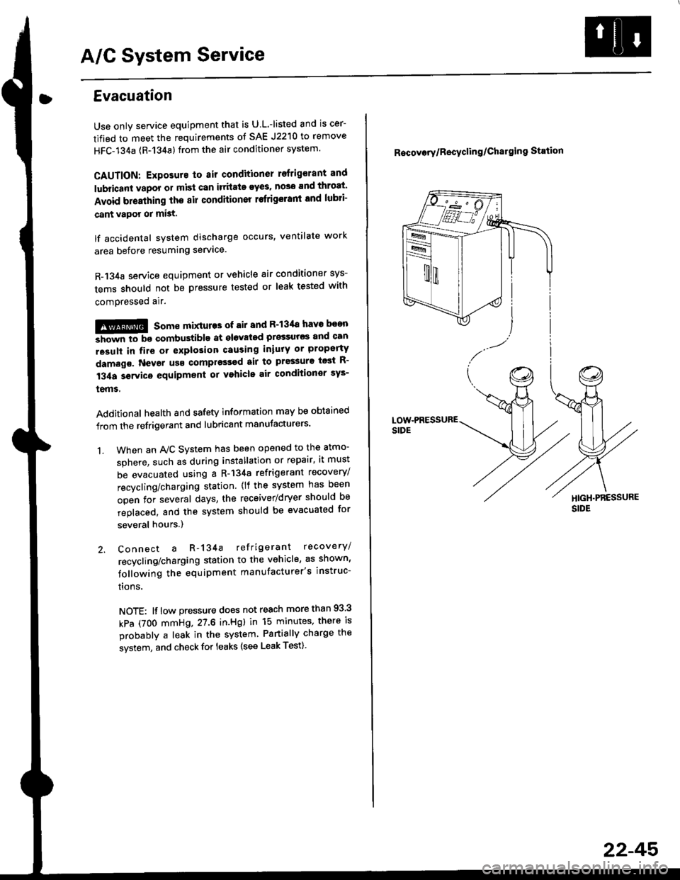
Connect a R-134a refrigerant recovery/
recycling/charging station to the vehicle, as shown'
following the equipment manufacturer's instruc-
trons.
NOTE: lf low pressure does not reach more than 93 3
kPa (7OO mmHg,27.6 in.Hgl in 15 minutes, there is
probably a leak in the system Partially charge the
system, and check for leaks (see Leak Test)
1.
R6covory/Recyclin g/Chal9ing Station
22-45'
Page 1470 of 2189
A/C System Service
Charging
Use only service equipment that is U.L.-listed and is cer-
tified to meet the requirements of SAE J2210 to remove
HFC-134a (R-134a) from the air conditioner system.
CAUTION: Exposure to air conditioner refrigerant and
lubricant vapor or mist can irritale eyes, nose and
throat. Avoid breathing the air conditioner retrigerant
and lubricant vaoor or mist,
lf accidental system discharge occurs, ventilate workarea before resuming service, Additional health and
safety information may be obtained from the refrigerant
and lubricant manufacturers.
Refrigerant capacityt 600 - 650 g 121.1 - 22.9 ozl
CAUnON: Do not overcharg€ the system; the comprcssor
will be damaged.
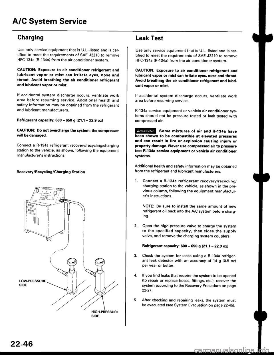
Connect a R-134a refrigerant recovery/recycling/charging
station to the vehicle, as shown, following the equipment
manufacturer's instructions.
Recovery/Recycling/Charging Station
22-46
Leak Test
Use only service equipment that is U.L,-listed and is cer-
tified to meet the requirements of SAE J2210 to remove
HFC-134a (R-134a) from the air conditioner system.
CAUTION: Exposure io air conditioner refrigerant and
lubricant vapot or mist can itritats eyes, no36 and thtoat.
Avoid breathing the air conditioner refrigeranl and lubri-
cant vapor or mist,
lf accidental system discharge occurs, ventilate workarea betore resuming service.
R-134a service equipment or vehicle air conditioner sys-
tems should not be pressure tested or leak tested with
comoressed air.
@ some mixtures of air and R-134a have
been shown to be combugtibls at elevatgd prossures
and can result in tire or explosion causing iniuly orplopgrty damage. Nev€r usc compre33od air to pressure
test R-13'la servica oquipment or yohiclo air conditionor
systems.
Additional health and safety information may be obtained
from the refrigerant and lubricant manufacturers.
1. Connect a R-134a refrigerant recove rylrecycling/
charging station to the vehicle, as shown in the pre-
vious column, following the equipment manufactur-
er's instructions.
NOTE; Be sure to install the same amount of new
refrigerant oil back into the A,/C system before charg-In9.
Open the high-pressure valve to charge the system
to the specified capacity, then close the supply
valve, and remove the charging system couplers.
Rofrigerant capacity: 600 - 650 g (21.1 - 22.9 oz)
Check the system for leaks using a R-134a refriger-
ant leak detector with an accuracy of 14 9 10.5 ozlper yea. or better.
lf you find leaks that require the system to be opened(to repair or replace hoses. fittings. etc.), recover the
system according to the Recovery Procedure on page
22-27.
After checking and repairing leaks. the system must
be evacuated (see System Evacuation on page 22-451.