2000 HONDA CIVIC low oil pressure
[x] Cancel search: low oil pressurePage 1075 of 2189
t
To STEERING GEARBOX
To STEERING GEAREOx
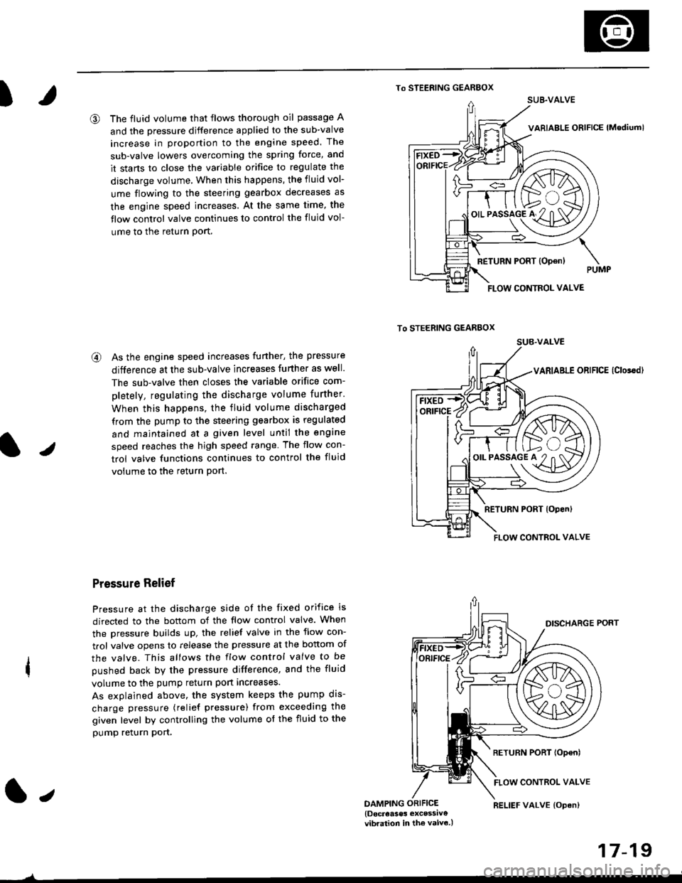
@ The fluid volume that flows thorough oil passage A
and the pressure djfference applied to the sub-valve
increase in proportion to the engine speed. The
sub-valve lowers overcoming the spring force, and
it stans to close the variable orifice to regulate the
discharge volume, When this happens, the fluid vol-
ume flowing to the steering gearbox decreases as
the engine speed increases. At the same time, the
flow control valve continues to control the fluid vol-
ume to the return Port,
@ As the engine speed increases funher, the pressure
difference at the sub-valve increases further as well.
The sub-valve then closes the variable orifice com-
pletely, regulating the discharge volume further.
When this happens, the fluid volume discharged
from the pump to the steering gearbox is regulated
and maintained at a given level until the engine
speed reaches the high speed range The flow con-
trol valve functions continues to control the fluid
volume to the return Port.
Pressure Relief
Pressure at the discharge side of the fixed orifice is
directed to the bottom of the flow control valve. When
the pressure builds up, the relief valve in the flow con-
trol valve opens to release the pressure at the bottom of
the valve. This allows the flow control valve to be
pushed back by the pressure difference, and the fluid
volume to the pump return port increases.
As explained above. the system keeps the pump dis-
charge pressure (relief pressure) from exceeding the
given level by controlling the volume of the fluid to the
pump relurn pon,
1.,DAMPING ORIFICE{Docreases excessiv€vibration in the valv6.)
17-19
)
RELIEF VALVE {Opan)
SUB.VALVE
FLOW CONTROL VALVE
/F ft>..\
'-€/K\A/A
o'.'to"5lo'#2"n af11\D7
FLOW CONTROL VALVE
Page 1081 of 2189
/
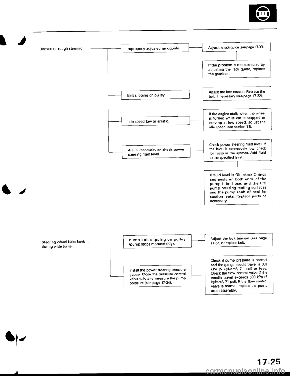
Uneven or rough steering
Steering wheel kicks back
during wide t!rns.
ll,
)
Adjust the rac* guide (see page 17-3).
lf the problem is not corrected bY
adjusting the rack guide, replace
the gearbox.
Adiust the belt tension. Feplace the
belt, il necessary (see Page 17 32).
lfthe engine stalls when the wheel
is turned while car is stopped or
moving at low speed, adjust the
idle spe€d (see section 11)
ldle speed low or erratic.
Check power sleering fluid level lf
the level is excessively low, check
lor leaks in the system. Add lluid
to the specified level.
Air in reservoir, or check Powersteering Iluid level.
lf ltuid level is OK, check O-rings
and seals on both ends of thepump inlet hose, and the P/Spump housing mating surfaces
and the pumP shaft oil seal for
suction leaks. RePlace Parts as
nocessary.
Adjust the belt tension (see Page17 32)or replace belt.Pump belt sliPPing on PLrlleY(pump stops momentarilY)
Check if pump press{rre is normal
and the gauge needle travel is 500
kPa (5 kgl/cm?, 7l Psi) or less.
Chock the flow control valve if the
needle travel exceeds 500 kPa (5
kgflcm'�, 71 Psi). l{ the flow control
valve is normal, replace the PumPas an assemoly.
Install the power steering pressure
gauge, Close the Pressure contrcl
valve fully and m6ssure the PumPpressure {s€e page 17-34}.
17 -25,
Page 1202 of 2189
L
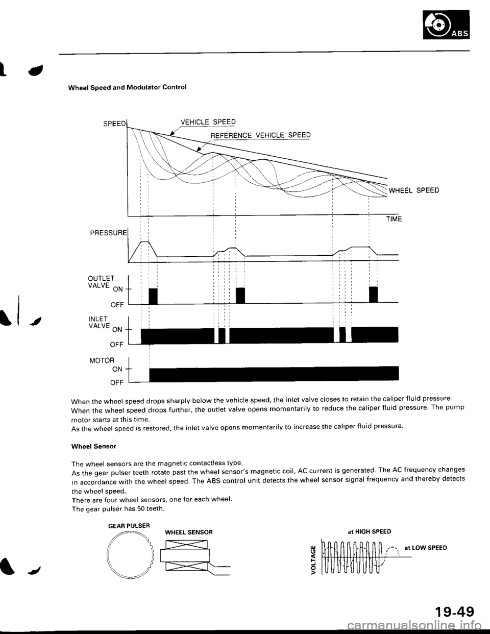
Wheel Soeed and Modulator Contlo
t
OUTLETVALVE ON
OFF
INLETVALVE ON
OFF
t\,40ToR
ON
OFF
when the wheel speed drops sharply below the vehicle speed, the inlet valve closes to retain the caliper fluid pressure
When the wheel speed drops further, the outlet valve opens momentarily to reduce the caliper fluid pressure. The pump
motor starts at this time.
As the wheel speed is restored, the inlet valve opens momentarily to increase the caliper fluid pressure.
Wheel SensoJ
The wheel sensors are the magnetic contactless type
As the gear pulser teeth rotate past the wheel sensor's magnetic coil, AC current is generated The AC frequency changes
in accordance with the wheel speed. The ABS control unit detects the wheel sensor signal frequency and thereby detects
the wheel speed.
There are four wheel sensors, one for each wheel
The gear pulser has 50 teeth.
EEL SPEED
at LOW SPEEDgl
=o
GEAR PULSEBWHEEL SENSOBat HIGH SPEED
/
19-49
Page 1429 of 2189
Description
Outline
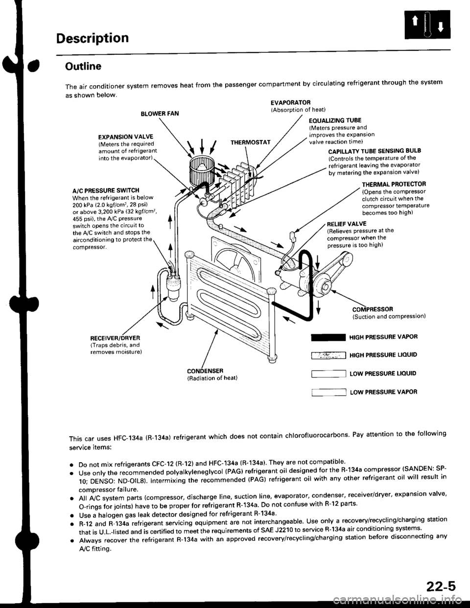
The air conditioner system removes heat from the passenger compartment by circulating refrigerant through the system
as shown below.
BLOWER FAN
EVAPORATOR(Absorption of heati
EOUALIZING TUBE(Meters pressure andimproves the expansionvalve reaction time)
into the evaporator)CAPILLATY TUBE SENSING BULB
lControls the temPerature of the
ref rigerant leaving the evaporator
by metering the expansion valve)
/\
THERMOSTAT
A/C PRESSURE SWITCH
When the refrigerant is below
200 kPa (2.0 kgtcm'�,28 Psi)or above 3,200 kPa 132 kgflcm',
455 psi), the Ay'C pressure
switch opens the circuit to
the A,/C switch and stops the
EXPANSION VALVE(Meters the requiredamount of refrigerant
airconditioning to Protect the
compressor.
RECEIVER/DRYER(Traps debris, andremoves morsturel
THERMAL PROTECTOR
{Opens the comPressorclutch circuit when the
compressor temPeraturebecomes too high)
RELIEF VALVE(Relieves pressure at the
compressor when thepressure is too high)
(Radiation of heat)
I
f-r-�-; I
(Suction and comPression,
HIGH PRESSURE VAPOR
HtGH PRESSUBE LIOUID
LOW PRESSURE LIOUID
This car uses HFC-134a (R-134a) refrigerant which does not contain chlorofluorocarbons Pay attention to the following
service items:
. Do not mix refrigerants CFC-12 (R-12) and HFC-134a (R-134a)' They are not compatible'
. Useonlythe recommended polyalkyieneglycol (PAG) refrigerant oil designedforthe R-134a compressor (SANDEN: SP-
10; DENSO: ND_OIL8). Intermixing ihe re-commended (pAG) refrigerant oil with any other refrigerant oil will result in
compressor failure.
. All A,,ic system parts {compressor, discharge line, suction line, evaporator, condenser, receiver/dryer, expansion valve'
O-rings for joints) have to be proper for refrigerant R- 134a Do not confuse with R-l2 parts'
. Use a halogen gas leak detector designed for refrigerant R-134a
. R-12 and R-134a refrigerant servacing equipment are not interchangeable. Use only a recovery/recycling/charging station
that is u,L.-listed and is certified to meet the requirements of sAE J2210 to service R-134a air conditioning systems'
. Always recover the refrigerant R-134a with an approved recovery/recycling/charging station before disconnecting any
A,/C fitting.
S]
22-5
Page 1446 of 2189
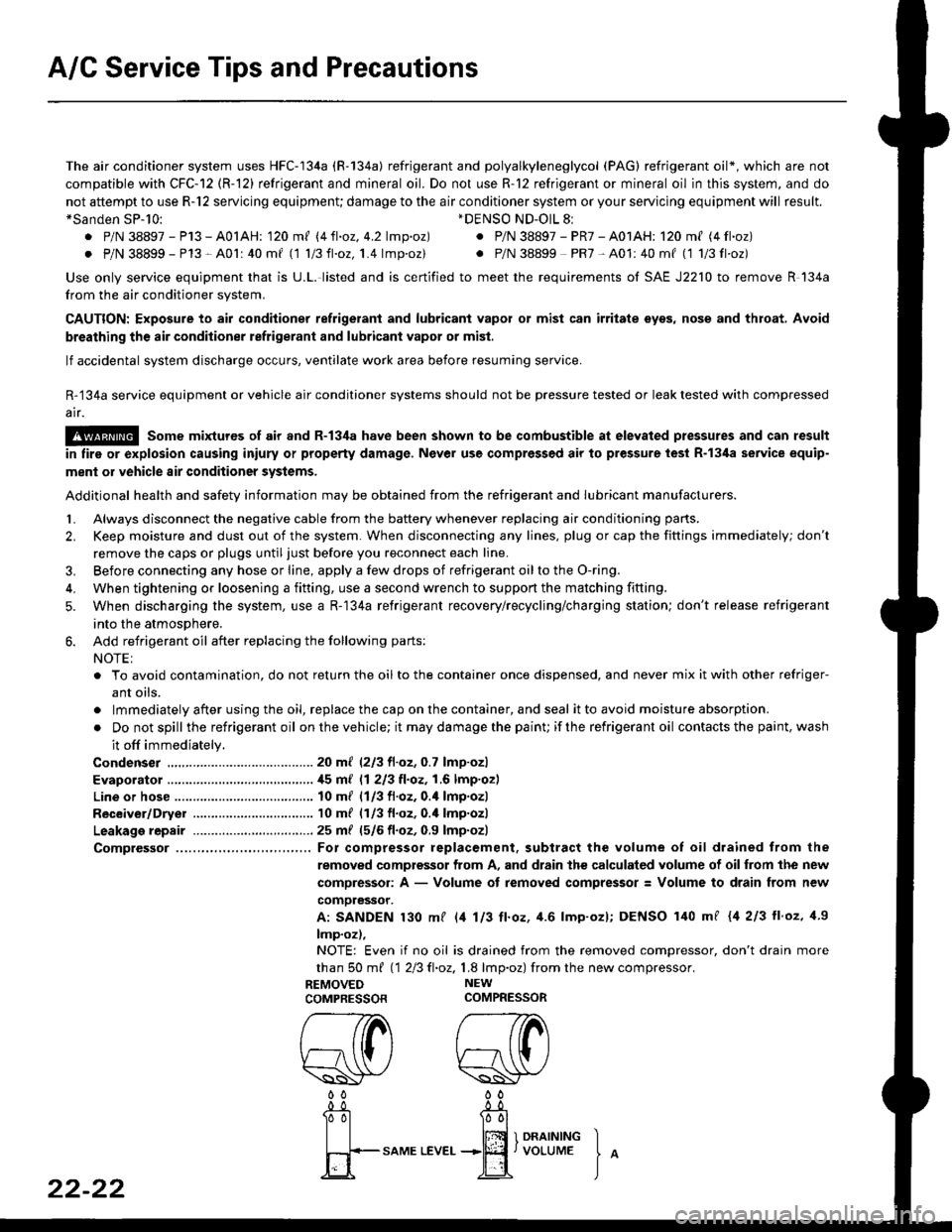
A/C Service Tips and Precautions
The air conditioner system uses HFC-134a (R-134a) refrigerant and polyalkyleneglycol (PAG) refrigerant oil*, which are not
compatible with CFC-12 (R-12) refrigerant and mineral oil. Do not use R-12 refrigerant or mineral oil in this system, and do
not attempt to use R-12 servicing equipmenU damage to the air conditioner system or your servicing equipment will result.*Sanden SP-10:
. P/N 38897 - P13 - A0lAH: 120 ml 14ll.oz, 4.2lmp.oz)
. P/N 38899 - P13 - A0l | 40 mf 11 1/3ll.oz,1.4 lmp'oz)
Use only service equipment that is U.L. listed and is certified to meet the requirements of SAE J2210 to remove R 134a
from the air conditioner system.
CAUTION: Exposure to air conditioner ref;ige;ant and lubricant vapol or mist can irritate syes, nose and throat, Avoid
breathing the air conditioner refrigerant and lubricant vapor or misl.
lf accidental system discharge occurs, ventilate work area before resuming service.
R-'134a service equipment or vehicle air conditioner systems should not be pressure tested or leak tested with compressed
ai.
!@@ some mixtures of air and R-t3ila have been shown to be combustible at elevated pressures and can result
in tire or explosion causing iniury or property damage. Never use compressed air lo pressure tesl R-134a service equip-
ment or vehicle 8ir conditioner systoms.
Additional health and safety information may be obtained from the refrigerant and Iubricant manufacturers.
L Always disconnect the negative cable from the battery whenever replacing air conditioning pans.
2. Keep moisture and dust out of the system. When disconnecting any lines, plug or cap the fittings immediately; don't
remove the caps or plugs until just before you reconnect each line.
3. Before connecting any hose or line, apply a few drops of refrigerant oilto the O-ring.
4, When tightening o. loosening a fitting, use a second wrench to support the matching fitting.
5. When discharging the system, use a R-134a refrigerant recovery/recycling/charging station; don't release refrigerant
into the atmosphere,
6. Add refrigerant oil after replacing the following parts:
NOTE:
. To avoid contamination, do not return the oil to the container once dispensed, and never mix it with other refriger-
ant oils.
. lmmediately after using the oil, replace the cap on the container, and seal it to avoid moisture absorption.
. Do not spill the refrigerant oil on the vehicle; it may damage the paint; if the refrigerant oil contacts the paint, wash
it off immediately.
Condenser .......2o ml (2/3 fl.oz, 0.7 lmp.ozl
Evaporator .,.,.,. i[5 m{ 11 213 tl.oz,1,6lmp.ozl
Line or hose ..... 10 mf (1/3 fl.oz, 0.4 lmp.ozl
Receiver/Dryer 10 m{ (1/3 fl.oz,0.'l lmp.ozl
Leakage repair 25 m{ (5/6 fl.oz, 0.9 lmp.ozl
Comptessor ... For compressor replacement. subtract the volume of oil drained trom the
removed compressor from A, and drain the calculated volume of oilfrom the new
compressor: A - Volume of removed compressor: Volume to drain from new
comoressor.
A: SANDEN 130 mf l/t 113 ll.oz, 4.6 lmp'ozl; DENSO 140 mf {4 213 ll'oz, 1.9
lmp.oz),
NOTE: Even if no oil is drained from the removed compressor, don't drain more
than S0 m{ 112Ell.oz,1.8 lmp.oz) fromthe new compressor.
REMOVED NEW
COMPRESSORCOMPRESSOR
*DENSO ND-OlL 8l
. P/N 38897 - PR7 - A01AH: 120 ml (4 fl.oz)
. P/N 38899 PR7-A01:40mf (1 1/3fl'oz)
rereW W0000
22-22
-0_!- -0_a
Tol l00l
| | lffi 1 onrrrutrc I
fi+-sAME
LEvEr...+jEf,voLUME
J
^
Page 1450 of 2189
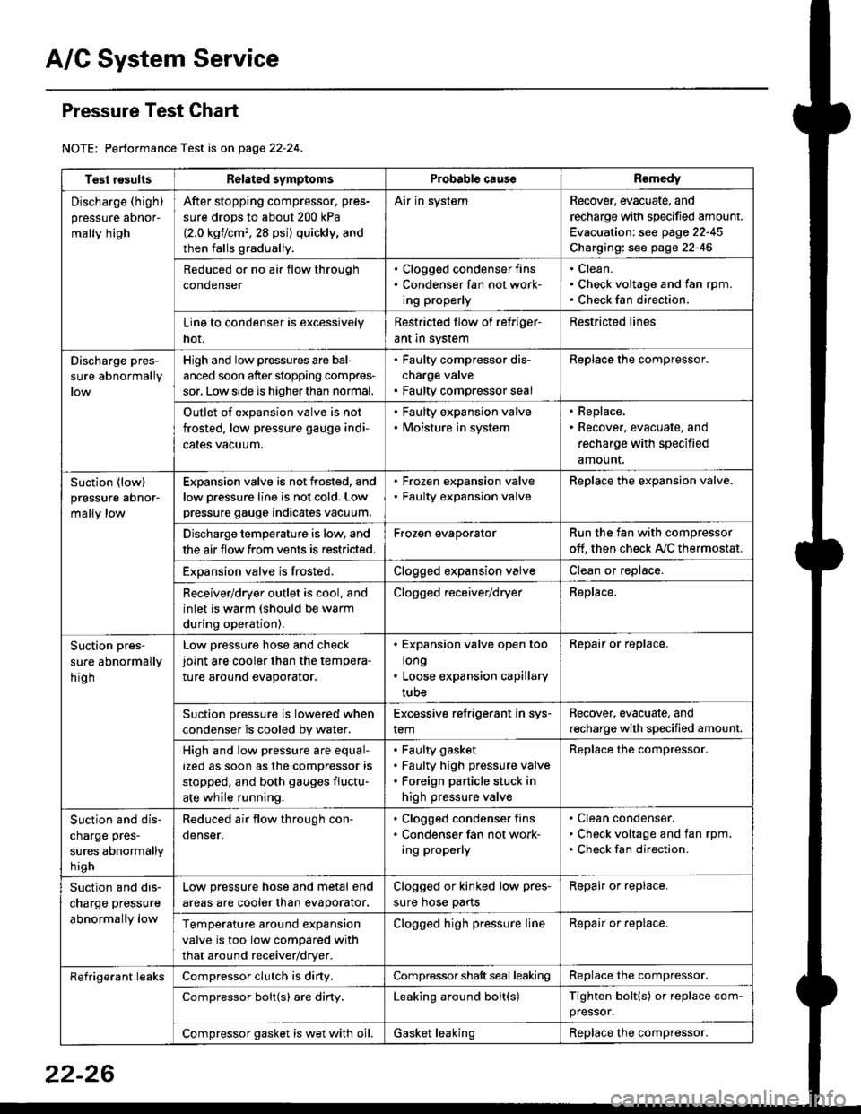
A/C System Service
Pressure Test Chart
NOTE: Performance Test is on page 22-24,
Test resultsRelated symptomsProbabl€ causeRemedy
Discharge (high)
pressure aDnor-
mally high
After stopping compressor. pres-
sure drops to about 200 kPa
{2.0 kgflcm,,28 psi) quickly, and
then falls gradually.
Air in systemRecover, evacuate, and
recharge with specified amount.
Evacuation: see page 22-45
Charging: see page 22-46
Reduced or no air flow through
condenser
. Clogged condenser fins. Condenser fan not work-
ing properly
Clean.
Check voltage and fan rpm.
Check fan direction.
Line to condenser is excessively
hot.
Restricted flow of refriger-
ant in system
Restricted lines
Discharge pres-
sure abnormally
High and low pressures are bal-
anced soon after stopping compres-
sor, Low side is higher than normal.
. Faulty compressor dis-
charge valve. Faulty compressor seal
Replace the compressor.
Outlet of expansion valve is not
frosted, low pressure gauge indi-
cales vacuum.
. Faulty expansion valve. Moisture in system
. Replace,. Recover, evacuate, and
recharge with specified
amount.
Suction (low)
pressure abnor-
mally low
Expansion valve is not frosted, and
low oressure line is not cold. Low
pressure gauge indicates vacuum.
. Frozen expansion valve. Faulty expansion valve
ReDlace the exoansion valve.
Discharge temperature is low. and
the air flow from vents is restricted.
Frozen evaporatorRun the fan with compressor
off. then check A,/C thermostat.
Exoansion valve is frosted.Clogged expansion valveClean or replace.
Receiver/dryer outlet is cool, and
inlet is warm (should be warm
during operation).
Clogged receiver/dryerReplace.
Suction pres-
sure abnormally
hig h
Low pressure hose and check
joint are cooler than the tempera-
ture around evaporator.
. Expansion valve open too
long. Loose expansion capillary
tube
Repair or replace.
Suction oressure is lowered when
condenser is cooled bv water.
Excessive refrigerant in sys-
tem
Recover. evacuate, and
recharge with specified amount.
High and low pressure are equal-
ized as soon as the compressor is
stopped, and both gauges fluctu-
ate while running.
Faulty gasket
Faulty high pressure valve
Foreign particle stuck in
high pressure valve
Replace the compressor.
Suction and dis-
charge pres-
sures abnormally
h igh
Reduced air flow through con-
denser.
. Clogged condenser fins. Condenser fan not work-
ing properly
Clean condenser.
Check voltage and fan rpm.
Check fan direction.
Suction and dis-
charge pressure
abnormally low
Low pressure hose and metal end
areas are cooler than evaporator.
Clogged or kinked low pres-
sure hose parts
Repair or replace.
Temperature around expansion
valve is too low compared with
that around receiver/dryer.
Clogged high pressure lineRepair or replace.
Refrigerant leaksCompressor clutch is diny,Compressor shaft seal leakingReplace the compressor.
Compressor bolt{s) are diny.Leaking around bolt(s)Tighten bolt(s) or replace com-
pressor.
Compressor gasket is wet with oil.Gasket leakingReplace the compressor.
22-26
Page 1451 of 2189
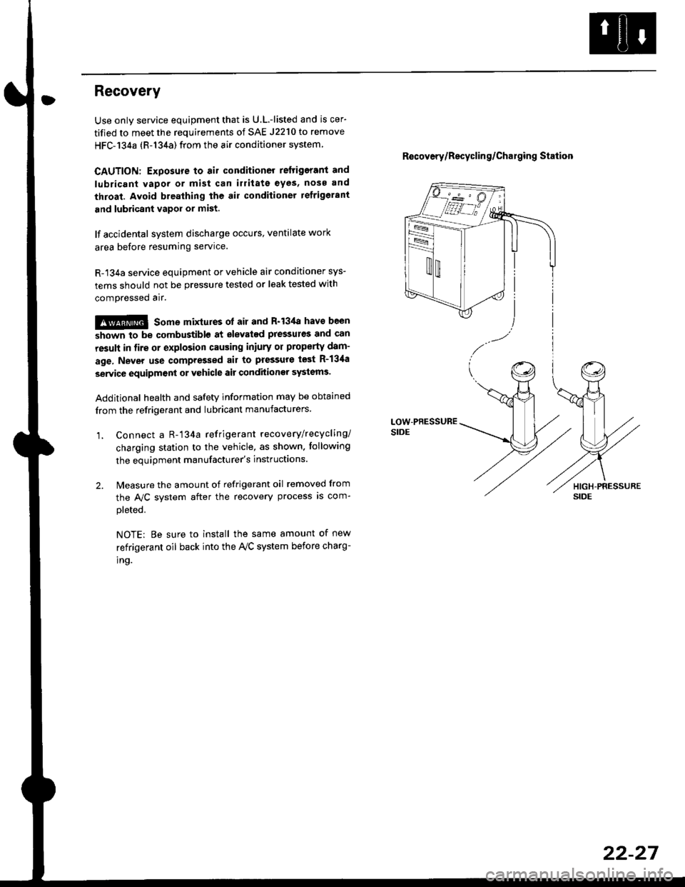
Recovery
Use only service equipment that is U.L.-listed and is cer-
tified to meet the requirements of SAE J2210 to remove
HFC-134a (R-134a) from the air conditioner system
CAUTION: Exposure to air conditioner relrigerant and
lubricant vapor or mist can illitate eyes, noss and
throat. Avoid breathing the ail conditioner refrigerant
and lubricant vapor or mist.
lf accidental system discharge occurs, ventilate work
area before resuming service.
R-134a service equipment or vehicle air conditioner sys-
tems should not be pressure tested or leak tested with
compressed air.
!@@ some mixtures ot air and R'13'[a havo been
strown to be combustiblg at elevated pressures and Gan
resuh in fire or explosion causing iniury or property dam-
age, Never use compressed air to pressure test R-134a
service equipment or vehicle air conditioner systems.
Additional health and safetv information may be obtained
from the refrigerant and lubricant manufacturers.
1, Connect a R-'134a refrigerant recove rylrecycling/
charging station to the vehicle, as shown. tollowing
the equipment manufacturer's instluctions.
2. Measure the amount of refrigerant oil removed from
the A/C svstem after the recovery process is com-
pleted.
NOTE: Be sure to install the same amount of new
refrigerant oil back into the Iy'C system before charg-
tno.
R€covery/Recyclin g/Cha19ing Station
22-27
Page 1464 of 2189
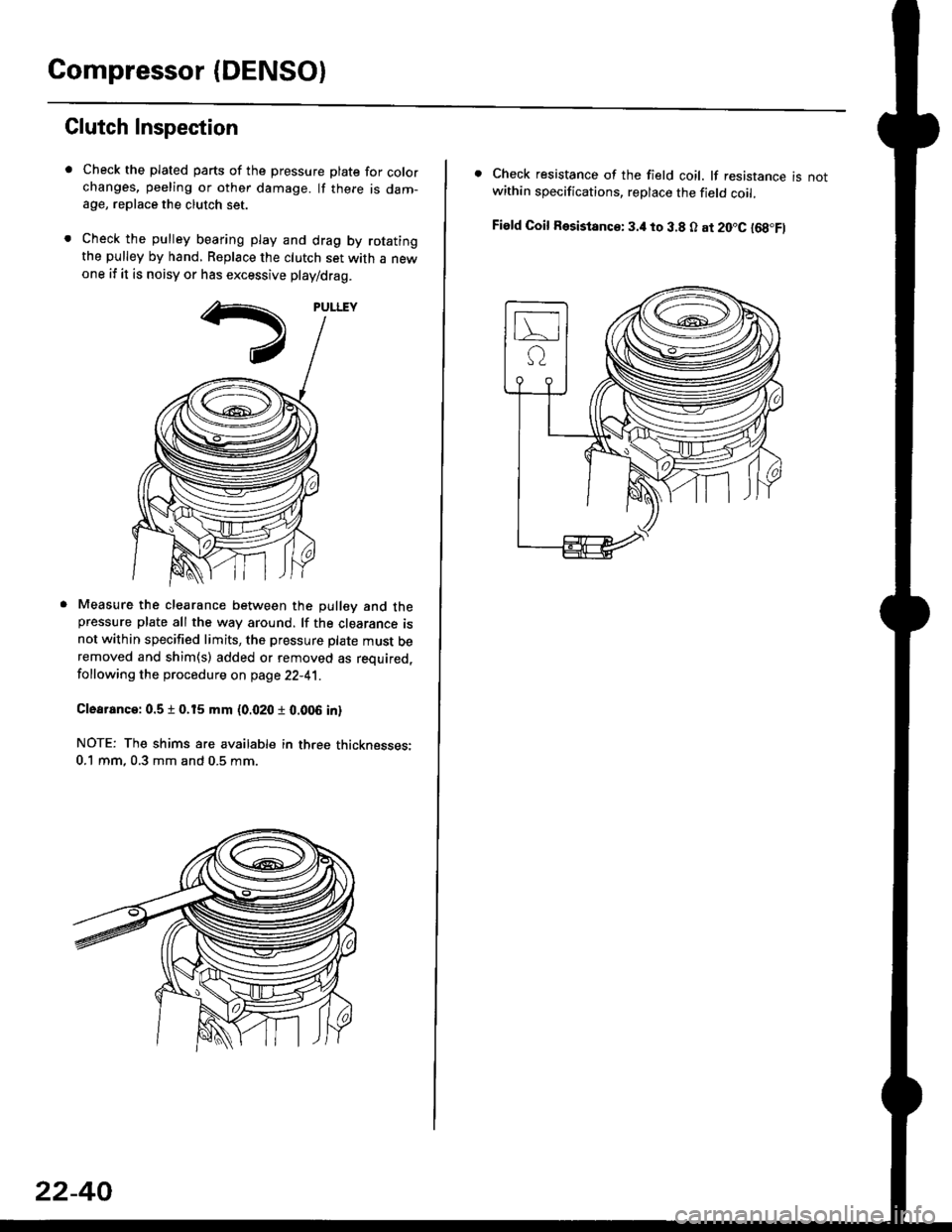
Compressor (DENSOI
Clutch Inspection
Check the plated parts of the pressure plate for colo.changes, peeling or other damage. lf there is dam-age, replace the clutch set.
Check the pulley bearing play and drag by rotatingthe pulley by hand, Replace the clutch set with a newone if it is noisy or has excessive play/drag.
Measure the clearance between the pullev and thepressure plate all the way around. lf the clearance isnot within specified limits, the pressure plate must beremoved and shim(s) added or removed as required,
following the procedure on page 22-41.
Clearanca:0.5 t 0.15 mm {0.020 r 0.006 in}
NOTE: The shims are availabte in three thicknesses:0.1 mm,0.3 mm and 0.5 mm.
22-40
. Check resistance of the field coil. lf resistance is notwithin specifications, replace the field coil.
Fiald Coil Resistanc€: 3.it to 3.8 O at 20.C l68.Fl