2000 HONDA CIVIC light
[x] Cancel search: lightPage 223 of 2189
CrankshaftOil Pan
Installation (cont'd)
NOTE:
. Apply a light coat of oil to the crankshaft and iothe lip of seal.. Use new O-rings and apply oil when installingthem.
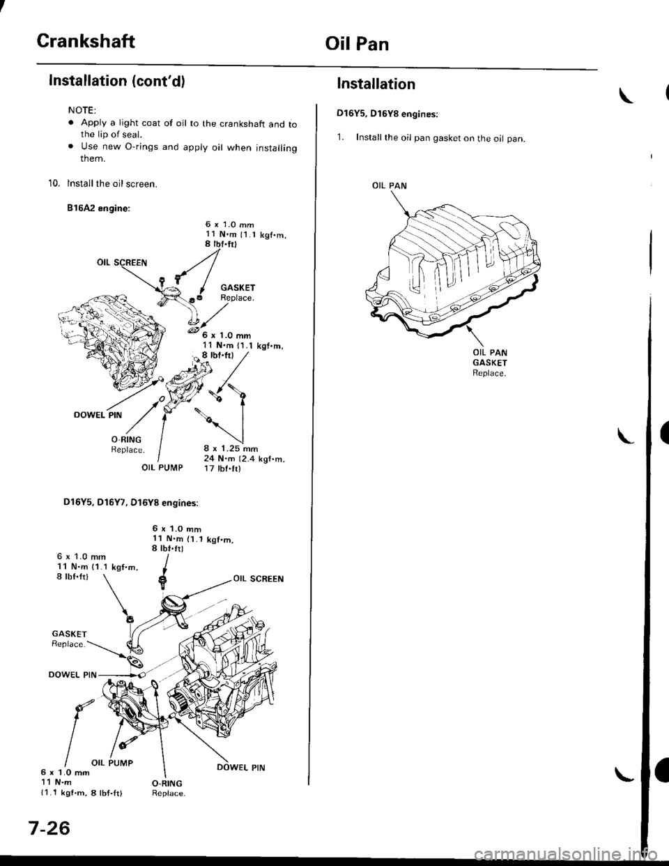
10. lnstallthe oil screen.
816A2 engine:
6 x 1.O mml l N'm (1 .1 kgl.m,8 tbt.Irl
,.//
{ / cor*rt(..ao Replace.
t(^^
11 N.m 11 .1 kgf.m,a lbl'ltl ,/.rB tbt4tl /
*P/
& ^/t
O.RINGReplace.
OtL PutitP
D16Y5, D16Y7, D16Y8 engines:
24 N.m (2.4 kgf.m,'17 lbl.fr)
kgf.m,
OIL SCREEN
6 x 1.0 mm1 1 N.m {1 .1 kgf.m,
6x1.0mm11 N.m {1.18 tbt.rr)
I
Ia lbf.fr)
DOWEL PIN
rT
lle/ OIL PUMP6 x 1.0 mm11 N.ml l.1 kgf'm, a lbf.frl
7-26
Installation
D16Y5, Dl6Yg engines:
1. Install the oil pan gasket on the oil pan.
OIL PANGASKETReplace.
OIL PAN
I
Page 226 of 2189

Oil Seals
lnstallation
NOTE:
. Engine removal is not required.
. The crankshaft oil seal housing should be dry.
Apply a light coat of grease to the crankshaft and to
the lips of the seals.
1. Using the special tool, drive in the timing pulley-
end seal until the driver bottoms against the oil
pump.
When the seal is in place, clean any excess grease
off the crankshaft and check that the oil seal lip is
not distorted.
07947 -S800200
lnstall seal with thepart number sadefacing out.
I
2. Measure the flvwheel-end seal thickness and the oil
seal housing depth. Using the special tool. drive the
flywheel-end seal into the rear cover to the point
where the clearance between the bottom of the oil
seal and the right side cover is 0.5 - 0.8 mm (0.02 -
0.03 in) (see page 7-23).
NOTE: Align the hole in the driver attachment with
the Din on the crankshaft.
DRIVER ATTACHMENT0794a-s800101lnslall seal with thepart number sidefacing out.
DRIVER07749-0010000
7 -29
Page 234 of 2189

Oil Filter
Replacement
After the engine has been run, the exhaust pipe willbe hot; be careful when working around ihe exhaustpipe.
Be careful when loosening the drain bolt whils theengine is hot. Burns can resuh because the oil tem-peratu16 is very high.
Remove the oil filter with the oil filter wrencn.
Inspect the threads and rubber seal on the new filter.Wipe off the seat on the engine block, then apply alight coat of oil to the new filter,s rubber seal.
NOTE: Use onty fitters with a built-in bypass sys,tem.
Apply oil to rubber sealbefore installing.
l.
Inspect threads andrubber seal surface.
8-8
Install the oil filter by hand.
After the rubber seal seats, tighten the oil filter clock_wise with the oil filter wrench.
Tighten: 7/8 tu.n clockwise.
Tightening tolque: 22 N.m (2.2 kgt.m, 16lbf.ft)
OIL FILTER WRENCH07912 - 6110001
Page 240 of 2189
Oil Pump
RemovaUlnspection/lnstallation (cont'dl
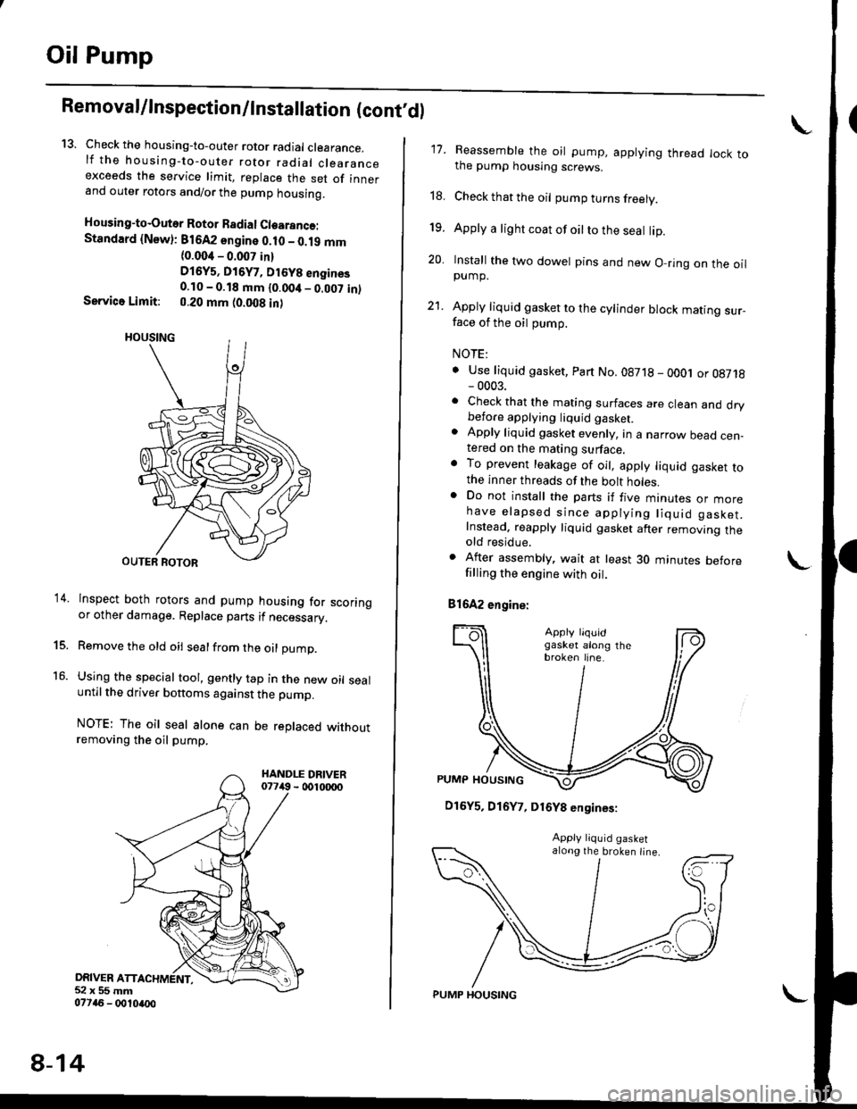
13. Check the housing-to-outer rotor radial clearance.lf the housing-to-outer rotor radial clearanceexceeds the service limit, replace the set of innerand outer rotors and/or the pump housing.
Housing-to-Outer Rotor Badial Clearanco:Standard {Newl: 816A2 sngine 0.10 - 0.19 mm(0.004 - 0.007 in)
D16y5, Di6y7, Dt6y8 engines0.10 - 0.18 mm {0.00it _ 0.007 in)Service Limit: 0.20 mm (0.008 in)
lnspect both rotors and pump housing for scoringor other damage. Replace parts if necessary.
Remove the old oil sealfrom the oil pump.
Using the special tool, gently tap in the new oil sealuntil the driver bottoms against the pump.
NOTE: The oil seal alone can be replaced withoutremoving the oil pump.
DRIVER ATT52x55mm077a6 - 0010ao0
14.
15.
16.
8-14
PUMP HOUSING
17. Reassemble the oil pump, applying thread lock tothe pump housing screws.
18. Check that the oil pump turns freely.
19. Apply a light coat of oilto the seal lip.
20. Install the two dowel pins and new O-ring on the oilpump.
21. Apply liquid gasket to the cylinder block mating sur_face of the oil pump.
NOTE:
. Use liquid gasket, Part No.08718 - oOOj or 08718- 0003.. Check that the mating surfaces are clean and drybefore applying liquid gaskel. Apply liquid gasket evenly, in a narrow bead cen-tered on the mating surface.o To prevent leakage of oil, apply liquid gasket tothe inner threads of the bolt holes.. Do not install the parts if five mtnures or morehave elapsed since applying liquid gasket.Instead. reapply liquid gasket after removing theold residue.
. After assembly, wait at least 30 minutes beforefilling the engine with oil.
81642 engine:
\
D16Y5, D16Y7, D16Y8 engines:
along the broken line.
Page 253 of 2189

TWCHO2S
Inspection
l. Using a flashlight, make a visual check for plugging,
melting and cracking of the catalyst.
D16Y5, D16Y7 engines:
816A2, D16Y8 engines:
-\6{-)\
lT
a
A
FLASHLIGI{T
9-12
Replacement
Primary HO2S:
1. Remove the primary HO2S.
D16Y5, D15Y7 engines:
a. Disconnect the primary HO2S connector, thenremove the cover.
8 x'1.25 mm24 N.m {2.4 kgl.m,
PRIMARY H02SCONNECTOR
b. Remove the primary HO2S.
| \l ,l(
I bK/l
l llw.
/
(
PBIMARY HO2S44 N m (4.5 kgf.m, 33 tbI.ft)
Page 353 of 2189
Troubleshooting
Troubleshooting Procedures (cont,dl
CAUTION:
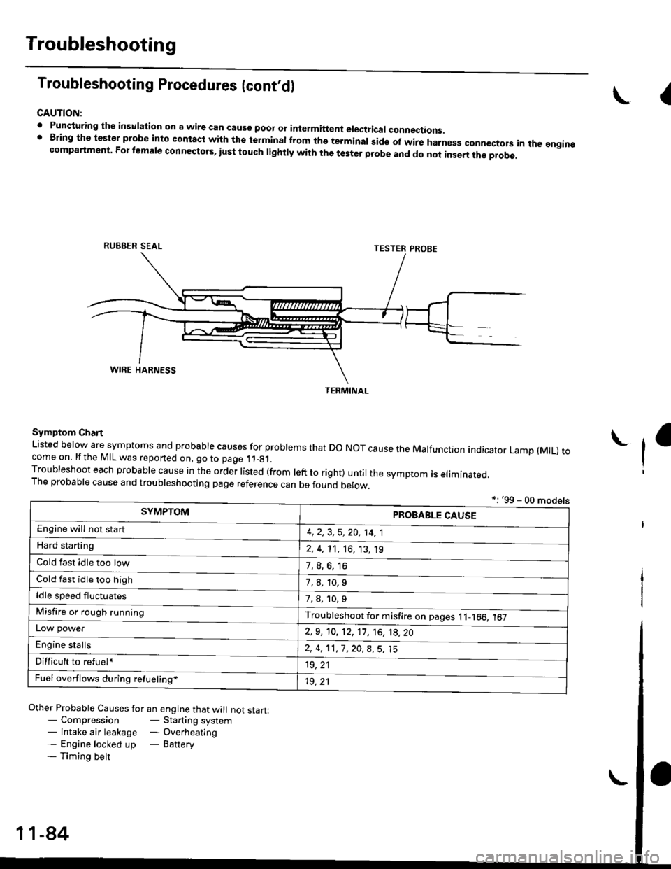
. Punqturing ihe insulation on a wirs can cause poor or intermiftent electricar connections.I Bring the test€r probe into contacl with the terminatlrom the terminal side of wire harnesg conncctors in the gngin€compartment. For temale connectors, iust touch lightly with the tester probe and do not inse.t the probe.
\I
RUBBER SEAL
Other Probable Causes for an engine that will not start:- Compression- Starting system- lntake air leakage - Overheating- Engine locked up - Battery- Timing belt
TESTER PROBE
Symptom Chart
Listed below are symptoms and probable causes for problems that Do NoT cause the Malfunction indicator Lamp (MlL) tocome on. lfthe MIL was reported on, go to page 11_81.Troubleshoot each probabre cause in the order risted (from reft to right) untir the symptom is eriminated.The probable cause and troubleshooting page reference can be found berow.
L
*: '99 - 00 models
TERMINAL
SYMPTOMPROBABLE CAUSE
4,2,3, 5,20, 14, 1
2, 4, 11, 16, 13, 't9
?, s^6. 16
1,8,10.9
Engine will not sta rt
Hard starting
Cold fast idle too low
Cold fast idle too high
ldle speed fluctuates7,8, 10.9
Troubleshoot for misfire on pages l1-166, 167Misfire or rough running
LOW power
E"g|* "t"lb
2,9, 10, 12, 11, 16, 't8,20
2,4,11,7,20,8,5,15
't9, 21
1r, ,1
Difficult to refuel*
Fuel overflows during refueling*
11-84
Page 358 of 2189
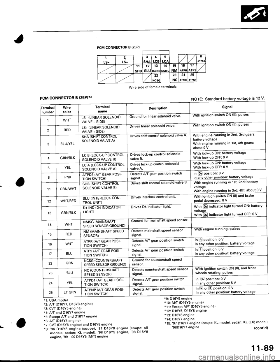
PCM CONNECTOR B {25P)
Wire side of {emale terminals
CONNECTOR B (25P)',
*1i USA model*2: A/T (D16Y7, Dl6Yg engine)*3: CVT (D16Y5 engine)*4: M and Dl6Y7 engane*5: Except A.rT and 016Y7 engine*6: A,/T (D16Y8 engine)*7r CVT (D16Y5 engine) and D16Y8 engine*8: '96 D16Y8 engine (coupe),'97 D16Y8
models, sedan: KL model),'98 Dt6Y5
engine,'99 00 Dl6Y5 1M/Ti engine
*9: D16Y5 engine*10: M/T (D16Y5 engine)*11: Except M/T {D16YS engine}*12i D16Y5, D16Y8 engine* 13: D16Y8 engine*14: D16Y7 engine*15: '97 Dl6YTengine (coupe: KL model, sedan: KL (LX) model)''98D16Y7 engine (cont,d)engine (coupe: allengine,'98 D16Y8
FCMNOTE: Standard battery voltage is 12 v'
erminalTnumoer
Wirecotol
TerminalnameDescriptionSignal
1LS_ (LINEAR SOLENOID
VALVE - SIDE)
Ground for linear solenoid valveWii-ignnion switctr oN {ll}: pulses
2REDLS+ (LINEAR SOLENOIDVALVE + SIDE)
-Drii6l linear solenoid valveWith ignilion switch uN (lll: pulses
3BLU/YEL
SHA {SHIFT CONTROLSOLENOID VALVE A)
-Drives shift control solenoid valve AWith engine running in 2nd,3rd gears:
battery voltageWith engine running in 1st,4th gears:
about 0 V
4GRN/BLKLC B (LOCK'UP CONTROL
SOLENOID VALVE B}Drives lock up control solenoid
valve B.
With lock-up ONI battery voltage
With lock-up OFF:0 v
5YELLC A (LOCK.UP CONTROLSOLENOID VALVE A)Drives lock up controlsolenoidWith lock-uP ON: baftery voltage
With lock-up OFFi 0 V
8PNKATPD3 (NT GEAR POSI.
TION SWITCHi
Detects Py'T gear Position switch
signal.
In [D31 position: 0 V
ln ;y other position: battery voltage
1lGRN^lr'HT
SHB (SHIFT CONTROLSOLENOID VALVE B)DnGs shift conttol solenoid valve BWith engine running in 1st,2nd: battery
vo|taqeWith;ngine running in 3rd,4th: about 0 V
12WHT/REDSLU (INTERLOCK CON
TBOL UNIT)
-DlivEilite'lock control,rnit.With ignition switch ON (ll) and brake
pedal depressed: 0 V
13GRN/BLK
D4 IND (D4 INDICATORLIGHT)
Drives D4 indicator light.With Pll indicator lrght turneo urr: oarterv
voltaoeWith ld indicator light turned OFF: 0 v
14WHTNMSG {MAINSHAFTSPEED SENSOR GROUND)
GZiiI'for mainshaft speed sensol
With engine running: Pulses
In E position: 0VIn any other position: battery voltage
REDNM {MAINSHAFT SPEED
SENSOR)
Detects mainshaft speed sensor
srgnal.
ATPR {M GEAR POSI
TION SWITCH)
Detects M gear Position switch
signal
't1BLUATP2 {A/T GEAR POSITION SWITCH)
Detects A/T gear Position switch
signal.
In E position: 0VIn any other position: battery voltage
22GRNNCSG (COUNTERSHAFT
SPEED SENSOR GROUND)Ground for countershaft speed
sensor.
23BLUNC (COUNTERSHAFT
SPEED SENSOR)
Detects countershaft speed sensor
signal.
Vvith ignition switch ON (ll), and front
wheels rotating: Pulses
24YELATPD4 {M GEAF POSI-
TION SWITCH)
Detects M gear Position switch
signal.
ln E position:0 VIn any other position: 5 V
25LT GRNATPNP (A"/T GEAR POSITION SWITCH)
Detects A/T gear Position switch
srgnal,
In E orE position:0 V
In any other position: battery voltage
!a
11-89
Page 360 of 2189
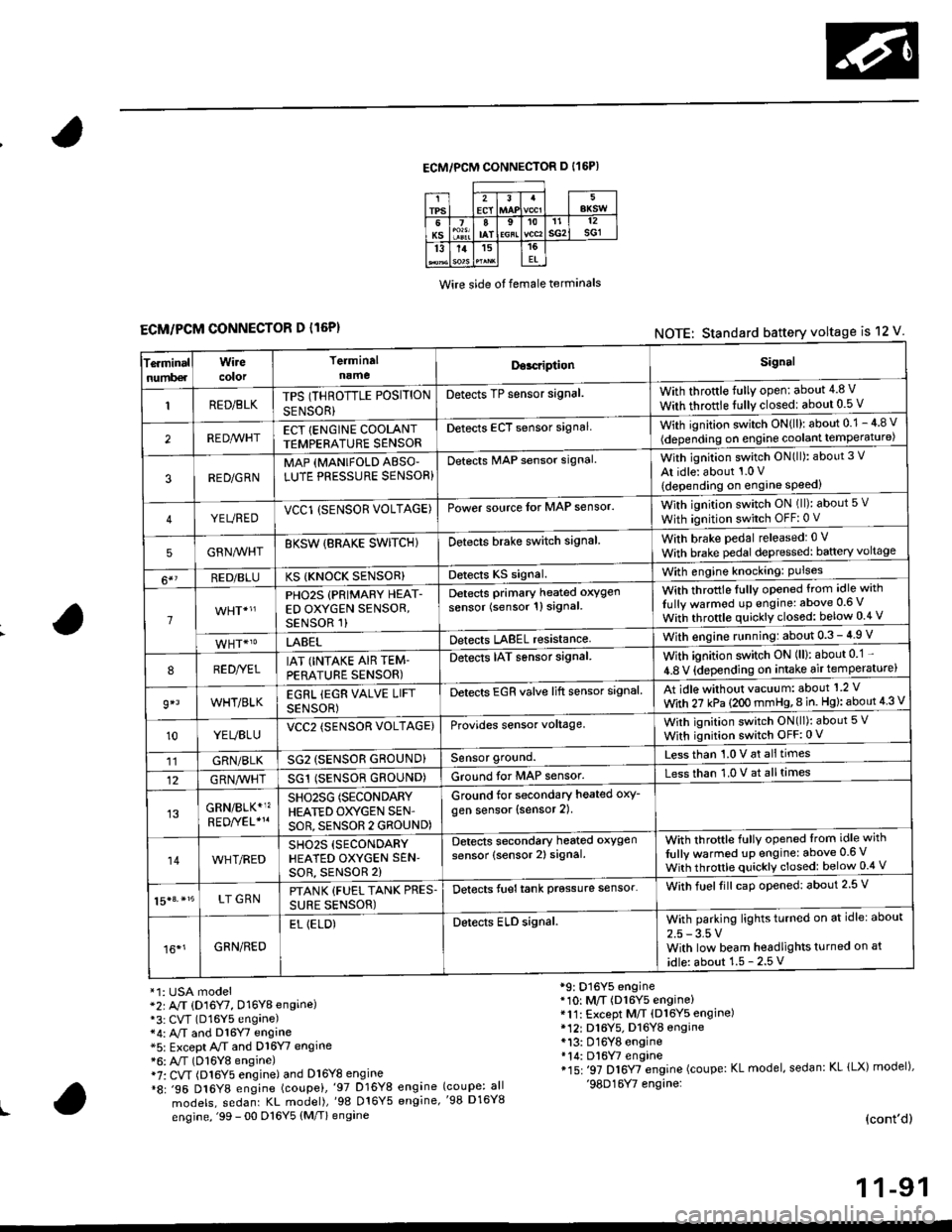
ECM/PCM CONNECTOR D I16P)
Wire side ot female terminals
ECM/PCM CONNECTOR D l16P)NOTE: Standard battery voltage is 12 V
Te.minalnumb€r
Wirecolor
Terminaln!meDor.riptionSignal
RED/BLKTPS (THROTTLE POSITION
SENSOR}
Detects TP sensor signal.With throttle fully open: about 4.8 V
With throttle fully closedl about 0.5 V
REDA/VHTECT {ENGINE COOLANTTEMPERATURE SENSORDetects ECT sensor signalWith ignition switch ON{ll): about 0.1 - 4 8 v
(depending on engine coolant lempe ratu re)
3RED/G RNMAP {MANIFOLD ABSO'LUTE PRESSURE SENSOR}Detects MAP sensor signal.With ignition switch ON(ll): about 3 V
At idle: about 1.0 V
{depending on engine speed)
YEUREDVCCl (SENSOR VOLTAGE)Power source lor MAP sensor.With ignition switch ON (ll): about 5 v
With ignition switch OFF: 0 V
5GRNMHTBKSW {BRAKE SWITCHIDetects brake switch signalWith brake pedal released: 0 v
With brake pedal depressed: baftery voltage
6*?RED/BLUKS {KNOCK SENSOR}Detects KS signal.With engine knocking: Pulses
1
PHO2S (PRIMARY HEAT-ED OXYGEN SENSOR,SENSOR 1)
Detects Primary heated oxygen
sensor (sensor 1l signal
With throttle fullv opened from idle with
Iully warmod up engine: above 0.6 V
With throttle quickly closed: below 0.4 v
LABELDetects LABEL resistanceWith engine r!nning:about 0.3 - 4.9 V
8RED//ELIAT (INTAKE AIR TEM-PERATURE SENSOR)
Detects IAT sensor signal.With ignition switch ON (ll): about 0 1 -
4.8 V {depending on intake air temperature)
9*lWHT/BLKEGRL iEGR VALVE LIFT
SENSOR)
Detects EGR valve lift sensor signalAt idle without vacuum: about'1 2 V
With 27 kPa (2OO mmHg,8 in. Hg): about 4 3 V
10YEUBLUVCC2 (SENSOR VOLTAGE)Provides sensor voltage,With ignition switch ON(ll): about 5 V
With ignition switch OFF:0 V
11GRN/BLKSG2 (SENSOR GROUND}Sensor ground.Less than 1.0 V at alltimes
12G RN,4/1r'HTSG1 (SENSOR GROUND)Ground for MAP sensor.Less than 1.0 V at alltimes
GRN/BLK*1?SHO25G (SECONDARY
HEATED OXYGEN SEN'
SOR, SENSOR 2 GROUND)
Ground for secondary heated oxy-
gen sensor (sensor 2).
14WHT/REDSH02S (SECONDARY
HEATED OXYGEN SEN'soR, sENsoR 2)
Detects secondary heated oxygen
sensor (sensor 2) signal.With throftle fully opened lrom idle with
fully warmed up engine: above 0.6 V
With throttle quickly closed: below 0.4 V
15|3. *15LT GRNPTANK {FUEL TANK PRES.
SURE SENSOR)
Detects fueltank prgssure sensor'With fuelfill caD opened: about 2.5 V
16*1GRN/RED
EL (ELD)Detects ELD signal.With parking lights turned on at idle: about
2.5 - 3.5 VWith low beam headlights turned on at
idle: about 1.5 - 2.5 V
*1: USA model*2r A/T (D16Y7, D16Y8 engine)*3: CVT (D16Y5 engane)*4: A,/T and Dl6Y7 engine*5: Except A/T and D16Y7 engine*6: A"/T (D16Y8 engine)i7: CVT (Dl6Y5 engine) and Dl6Y8 engine*8: .96 D16Y8 engine (coupei,'97 D16Y8 engine
models, sedanr KL model),'98 016Y5 engine,
engine, '99 - 00 D16Y5 (M/T) engine
*9: D16Y5 engine*10: M/T (D16Y5 engine)*11: Except M/T (Dl6Y5 engine)* 12r D16Y5. D16YB engine*13: D16Y8 engine*14: Dl6W engine*15: '97 D16Y7 engine (coupe: KL model, sedan: KL lLX) model),'98D16Y7 engine:(coupe: all'98 D16Y8
(cont'd)
1 1-91