Page 1573 of 2189
lgnition System
-Circuit Diagram: '96 - 97 models
.i-
8LU
I
nBLU BLU I
tl
lnI TESTI TACHOMETEF\-7 CONNECTOR
TACHOMETERTCM (CW)
J-) {sh,eldinsr't I
tfYEL BBN/BLK
+l
I:
G101
$t+++
UNDER HOOD FUSE/ RELAY 8OX
BLh TEL YEL GBN
BLKlYEL
IAl
BLK/YEL YELIGFN
IGN]TIONCOL
TDCrTop dead cenlerCKP: Crankshall postionCYP Cylnder poslon
TDC]CKP]CYP SENSoR
" *]BLU'*2 WHI BLU
IGNITION CONIROLMODULE (CM)
/ Has b'r ll n\I iorse I
rUSE FE-AV BO}
*u r-. .-*---{<9ot # u,,."r. | |
\j/ El v
tl
23-103
Page 1604 of 2189
Gauge Assembly
Circuit Diagram (cont'dl
MATFUNCTIONINOICATOR
(M r)
WASHERLEVELSWITCHTclosed :Floatdownltopen Floal up .l
PNK
BLK
T
G401G402
GRN/ORN
I
ECM/PCM
ENGINEorLPRESSURESWITCHfcbsed Enqine
BLU/BLK YEURED
HI
'f''#lu""',.'f
--
RED/BLU
| ffitt'*'
IV
tl
tl
REDi BLU
I o, u,,,
/h,, SEii
Y rtt'J"T,r.0,.*"0
I
topen Buchred
BLK
T
G552
Page 1703 of 2189
Driver's Window Motor Test
Motor Test:
l. Remove the driver's door panel (see section 20).
Terminal side of male terminals
Disconnect the 4P connector from the motor.
Test the motor in each direction by connecting bat-
tery power and ground according to the table.
CAUTION: When th€ molor stops running, discon-
n€ct one lead immediat€ly.
4. lf the motor does not run or fails to run smoothlv.
reDlace it.
3.
l.,,
Terminal
;."t1."
-_l\1
UPo@
DOWNoo
Puls€r Test:
5. Connect the test leads of an analog ohmmeter to the
No. 3 and No. 4 terminals.
6. Run the motor by connecting power and ground to
the No. 1 and No.2 terminals. The ohmmeter needle
should move back and forth alternately.
23-233
Page 1704 of 2189
Power Windows
Passenger's Window Motor Test
Front:
1. Remove the passenger's door panel (see section
20t.
2. Disconnect the 2P connsctor from the window
moIor.
2P CONNECTOR
\
Terminal side ot msleterminals
3. Check window motor operation by connecting power
and ground according to the table.
CAUTION: When the motor stops running. dbcon-
nest ono load immadiatoly.
4. lf the motor doas not run or fails to run smoothly.
replace it.
Terminal
;;,r";--lI
UP@o
DOWN@
23-234
Re!r:
1. Remove the passenger's door panel {see section
20).
2. Disconnect the 2P connectof from the window
motor.
NOTE: The illustration shows the right rear window
motor; the left rear window motor is symmetrical.
2P CONNECTOR
3. Check window motor operation by connecting power
and ground according to the table.
GAUTION: Whon the motor ctops running, discon-
nact one lead immodiatoly.
4. lJ the moto. does not run or fails to run smoothly.
rcDlace it,
Terminal
DI;t;;---l
UPo@
DOWN@
Page 1748 of 2189

Preca utions/Procedures
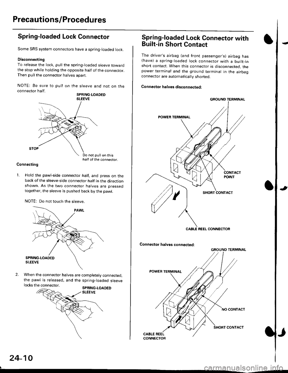
Spring-loaded Lock Connector
Some SRS system connectors have a spring-loaded lock.
Disconnecting
To release the lock, pull the spring-loaded sleeve towardthe stop while holding the opposite half of the connecror.Then pull the connector halves apart.
NOTE: Be sure to pull
connector half.
on the sleeve and not on the
SPRING-LOADEOSLEEVE
Do not pull on thishalf of the connector.
Connecting
1. Hold the pawl-side connector half, and press on theback of the sleeve-side connector half in the directionshown. As the two connector halves are pressed
together, the sleeve is pushed back by the pawl.
NOTE: Do not touch the sleeve.
When the connector halves are completely connected,the pawl is released, and the spring-loaded sleevelocks the connector.SPRING.LOADEDSLEEVE
24-10
Spring-loaded Lock Connector with
Built-in Short Contact
The driver's ajrbag (and front passenger,s) airbag has(have) a spring-loaded lock connector with a builr-inshort contact. When this connector is disconnected, thepower terminal and the ground terminal in the airbaaconnector are automatically shoned.
Connector halves disconnected:
SHORT CONTACT
Conneqtor halves connected:
GROUND TERMINAL
CABLE REEL CONNECTOR
GROUND TERMINAL
Page 1750 of 2189

Precautions/Procedu res
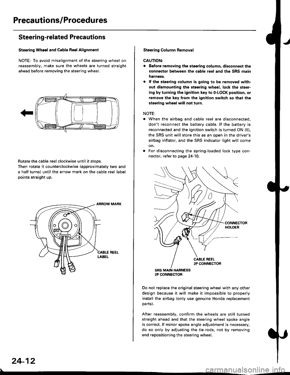
Steering-related Precautions
Stesring Wheel and Cable Reol Alignment
NOTE: To avoid misalignment of the steering wheel on
reassembly, make sure the wheels are turned straight
ahead before removing the steering wheel.
Rotate the cable reel clockwise until it stops.
Then rotate it counterclockwise {approximately two and
a half turns) until the arrow mark on the cable reel label
points straight up.
24-12
:l
St€€rin9 Column Removal
CAUTION:
. Eefore removing thg stggring column. disconnect the
connsstor bqtween the cable r€el and th€ SRS msin
harness.
. lf the stoering column is going to be romoved with-
out dismounting th6 stoering wheel, lock the steer-
ing by turning the ignition key to o-LOCK position, or
remove the key trom the ignition switch so that the
steering wheel will not turn.
NOTE:
When the airbag and cable reel are disconnected,
don't reconnect the battery cable. lf the battery is
reconnected and the ignition switch is turned ON (ll),
the SRS unit will store this as an open in the driver's
airbag inflator, and the SRS indicator light will come
on.
For disconnecting the spring-loaded lock type con-
nector, refer to page 24-'10.
SRS MAIN HARNESS2P CONNECTOR
Do not replace the original steering wheel with any other
design because it will make it impossible to properly
install the airbag (only use genuine Honda replacement
parts).
After reassembly, confirm the wheels are still turned
straight ahead and that the steering wheel spoke angle
is correct. lf minor spoke angle adjustment is necessary,
do so only by adjusting the tie-rods, not by removing
and repositioning the steering wheel.
Page 1795 of 2189
)From page 24-56
Check lor a short to ground in tha SRS main haino$:
1. Disconnect th€ battery negative cable. then disconnect
the positive cable, and wait for three minutes
2. Disconnect the driver's airbag 2P connector from the
cable reel 2P connector'3. Disconnect the SRS main harness 18P connector from
the sRS unit.4. Remove the special tool (2 0) from the SRS main harness
2P connector,5. Check resistance b€tween the No. 10 terminal ol the SRS
main harness 18P connector and ground, and between
the No. 14 terminal ot the SRS main harnoss 18P connec
tor and ground. There should be 1 N/10 or more'
k tho rod.tanco .3 3pocified?
YESNO
Faulty SRS unit; topl.co the SRS unit (seo page 24-761'
Short to giound in the SRS msin hamets; replacc th€ SBS
main harno33.
SRS UNlT
SRS MAIN HARNESS18P CONNECTOR
O l,t
24-57
Page 1812 of 2189

Cable Reel
Replacement (cont'd)
11.
NOTE:
. Before installing the steering wheel, the front
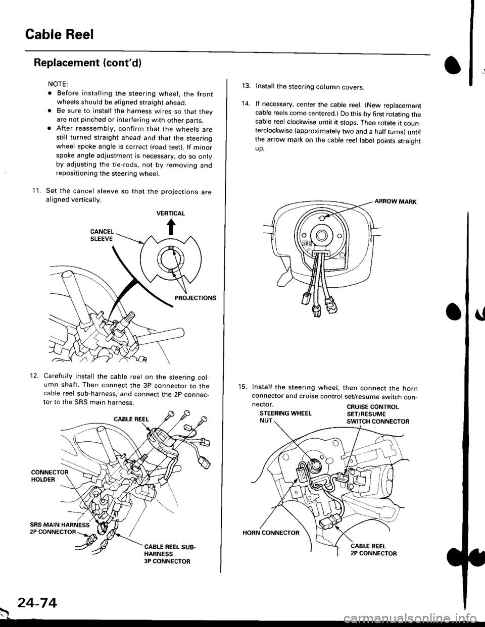
wheels should be aligned straight ahead.. Be sure to install the harness wires so that theyare not pinched or interfering with other parts.. After reassembly. confirm that the wheels arestill turned straight ahead and that the steeringwheel spoke angle is correct (road test). lf minor
spoke angle adjustment is necessary, do so onlyby adjusting the tie-rods, not by removing andrepositioning the steering wheel.
Set the cancel sleeve so that the projections arealigned venically.
PROJECTIONS
12. Carefully install the cable reel on the steering column shaft. Then connect the 3p connector to thecable reel sub-harness, and connect the 2p connec-tor to the SRS main harness.
. 24-74
Install the steering column covers.
lf necessary, center the cable reel. {New replacementcable reels come centered.) Do this by first rotating thecable reel clockwise until it stops. Then rotate tt counterclockwise (approximately two and a half turns) untilthe arrow mark on the cable reel label points straightup.
ARROW MARK
15. lnstall the sleering wheel, then connect the hornconneclor and cruise control sevresume switch con
14.
neclor.
STEERING WHEELCRUISE CONTROLSET/RESUM€