2000 HONDA CIVIC Top
[x] Cancel search: TopPage 2008 of 2189
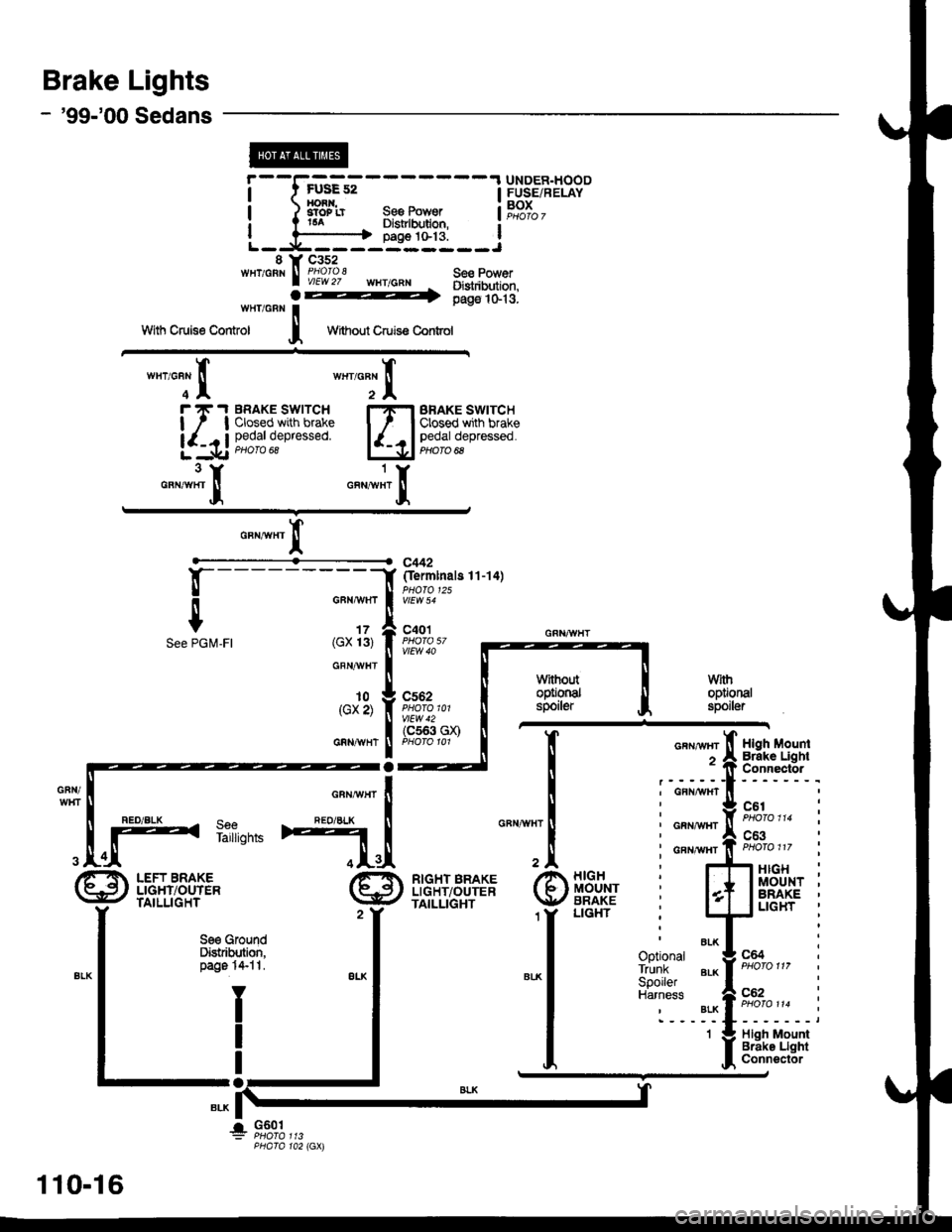
Brake Lights
- '99100 Sedans
s Y c3s2wHT/cBN I Ploroz' wHrrGRNo-l.
'_-._-_:---- UNDER.HOODt-u!E az I ErreE/oEr AvI FUSE/RELAYxonn,aToP rrt6aSso PowerDistrlbdlon,a?,oJ.,
| ?--'-----------t oaoe tG13. IL--:t------------J
Se€ PowerOigtribution,pags 1G13.wfrr/GBN iWith Cruise Control I
!--
$PGI\,4-FI
Without Cruis€ Contd
BRAKE SWITCHClosed with brakepedal depressed.PHOTO 8
o"na", I
--f (fermtnals 1'l-'14)
o""-", I ff,o*tuo. t"
,o*11, I Fol%' -,, - v{w, GR{GX 131 I PrOrO 5/ ----
o"n*"t I ll
! tl wrhoutrn ! n
*"*",1 if;#,,o1 |
-l-
__""*!m4",;,"' l| [
4;[
vfithoplionalspoiter
,.Fr[ RtcHT BRAKE /t rllcH
LE€,, ffL',61g." \9/ $"'f,iJ2Y 1Y LIGHr
S€€ GroundDist bution,page 1+1t.
I
I
Io
G601
110-16
!
Page 2018 of 2189
Power Windows (contd)
- How the Circuit Works
CAUTION: You could iniure your arms, hands, or
fingers if you unintentionally switch the driver's
window to "automatic down" while working in
that door with the power on. Disconnect the
window switch conneclot or the battery when
working in the driver's door.
System Description
The operation of the power windows is controlled by
the main switch in the power window master switch.
When the main switch is in OFF, only the driver's door
window can be opened or closed. With the main
switch ON, all windows can be ooened or closed
either by swtches in the master panel, or swttches in
the doors. The driver's window switch also has an
automatic down mode which is tumed on by pushing
the switch down to its second oosition.
The power windows are driven by reversible motors.
Each motor is protect€d by a built-in circuit breaker.
lf the window switch is held on too long (with the
window obstructed, or after the window is fully up or
down), the circuit breaker opens the circuit. The
circuit breaker resets automaticallv as it cools.
Driver's Window
With the ignition switch in ON, voltage is provided to
the coil of the power window relay through fus€ 24.
The contacts of the power window relay close, and
voltage is applied to the driver's switch. When you
push the power window master switch to UP, voltage
is applied to the driver's window motor. (The motor's
ground path is back through the master power
window switch.) The driver's window motor then
drives the window up. When you push the switch to
DOWN, voltage is applied in the opposite direction
and the motor drives the window down.
Automatic Down (Driver's Window)
With the ignition switch in ON or START, voltage is
applied to the coil of the power window relay. The
contacts of the power window relay close and
voltage is applied lo the power window master
switch. When you push the driveas switch to the
AUTO DOWN position, voltage is applied through
the driver's switch to the driver's window motor. The
control unit receives pulses at the pulser input while
the motor is running. When the window is fully
down, the motor stops, and pulses are no longer
generated by the pulser. This is sensed by the
control unit at the pulser input, and voltage is no
longer applied to the driver's window motor.
Passenger Windows
With the ignition switch in ON, voltage is applied to
the coil of the power window relay through fuse 24.
The contacts of the power window relay then close,
applying voltage to the individual window switches
and the power window master switch. With the
master panel main switch ON, the passenger
windows can be ooerated from the individual
window switches or from tho master panel switches.
When you push the front passengsr's window
switch to UP, voltage is applied to the f ront
passenger's window motor. (The motor is grounded
through the contacts in the front passenger's
window switch and the oower window master
switch.) The window moves up as long as you hold
the switch in the UP position. lf you push the switch
to DOWN, voltage is applied in th€ opposite
direction to the front passenger's window motor, and
the window movss down as long as you hold the
switch in the DOWN Dosition. The window switches
in the other doors operate similarly.
When you push the front passenger's switch in the
master panel to UP, voltage is applied through the
front passenger's window switch contacts to the
front passengefs window motor. (The motor is
grounded through the contacts in the front
passenger's window switch and the power window
master switch.) The window moves up as long as
you hold the switch in the UP position. lf you push
the switch to DOWN, voltage is applied in the
opposite direction to lhe front passenger's window
motor, and the window moves down as long as you
hold the switch in the DOWN position. The other
passenger window switches in the master panel
operate similarly.
Refer to the Service Manual (Section 23, Electrical)
for specific tests or troubleshooting procedures.
120-4
Page 2027 of 2189
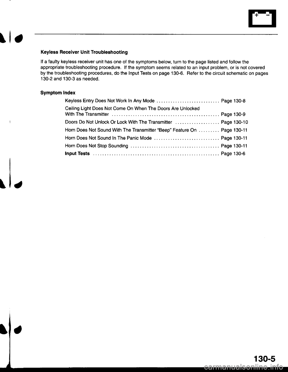
Keyless Receiver Unit Troubleshooting
lf a faulty keyless receiver unit has one of the symptoms below, turn to the page listed and follow the
appropriate troubleshooting procedure. lf the symptom seems related to an input problem, or is not covered
by the troubleshooting procedures, do the Input Tests on page 130-6. Refer to the circuit schematic on pages
1 30-2 and 130-3 as needed.
Symptom Index
Keyless Entry Does Not Work In Any Mode
Ceiling Light Does Not Come On When The Doors Are Unlocked
WithTheTransmitter ....
Doors Do Not Unlock Or Lock With The Transmitter . . . .
Horn Does Not Sound With The Transmitter "Beeo" Feature On
Horn Does Not Stop Sounding .......
Input Tests
Page 130-8
Page 130-9
Page 130-1 0
Page 130-11
Page 130-11
Page 130-11
Page 130-6
.1,
Page 2033 of 2189
a
Horn Does Not Sound In The Panic
Mode Or With The Transmitter "Beep"
Feature On
NOTE: The transmitter has a Beep On/Off feature.
Refer to page 130-4 for how to tum the beep on or
off.
1. Does the horn sound when the HORN button is
oressed?
Yes - Go to the next steD.
No - Repair the horn circuit.
2. Does the transmittor LED come on when any of
the buttons are pressed?
Yes - Go to the next step.
No - Check the transmitter battery then retest.
ll the beep feature still does not work, go
to the next steo.
3. Recheck with a known good transmitter
reprogrammed to the vehicle. Does the system
work properly in all modes?
Yes - Replace and program the transmitter,
then retest. Use the procedure on page
1 30-4 f or transmitter programming.
No - Go to the next step.
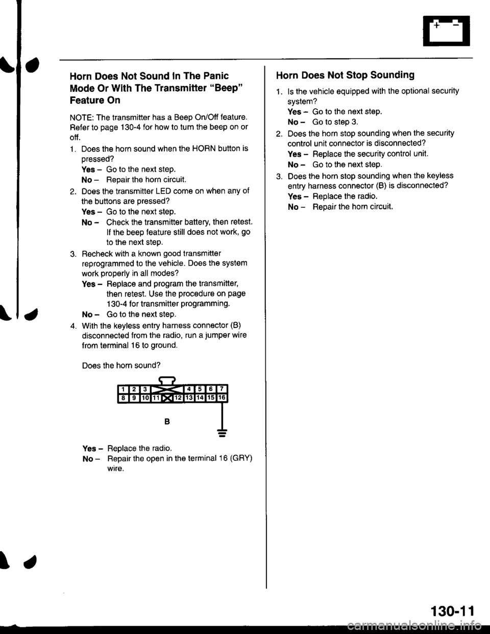
4. With the keyless entry harness connector (B)
disconnected from the radio, run a.iumper wire
f rom terminal 16 to ground.
Does the horn sound?
Yes - Reglace the radio.
No - Repair the open in the terminal 16 (GRY)
wire.
\
Horn Does Not Stop Sounding
1. ls the vehicle equipped with the optional security
system?
Yes - Go to the next step.
No - Go to step 3.
Do€s the horn stop sounding when the security
control unit connector is disconnected?
Yes - Replace the security control unit.
No- Go to the next step.
Does the horn stop sounding when the keyless
entry harness connector (B) is disconnected?
Yes - Reolace the radio.
No - Reoair the hom circuit.
130-11
Page 2037 of 2189
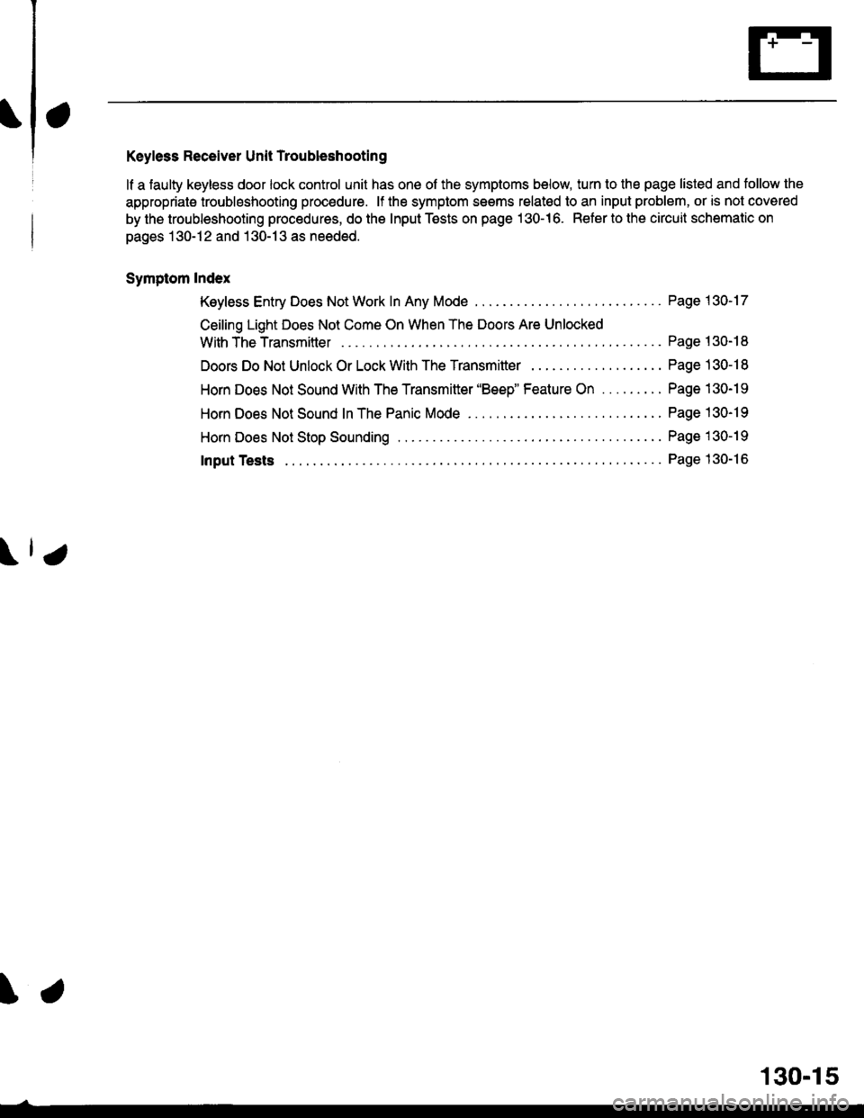
Keyless Receiver Unit Troubleshooting
lf a faulty keyless door lock control unit has one of the symptoms below, turn to the page listed and tollow the
appropriate troubleshooting procedure. lf the symptom seems relatod to an input problem, or is not covered
by the troubleshooting procedures, do the Input Tests on page 130-16. Refer to the circuit schematic on
pages 130-12 and 130-13 as needed.
Symptom Index
Keyless Entry Does Not Work In Any Mode
Ceiling Light Does Not Come On When The Doors Are Unlocked
With TheTransmitter ....
Doors Do Not Unlock Or Lock With The Transmitter . .
Horn Does Not Sound With The Transmitter 'Beep" Feature On .........
Horn Does Not Sound In The Panic Mode ..
HornDoes NotStopSounding ...............
Page 1 30-17
Page 130- 18
Page 130-1 I
Page 130-19
Page 130-19
Page 1 30-19
Page 130-16Input Tests
\.
130-15
Page 2041 of 2189
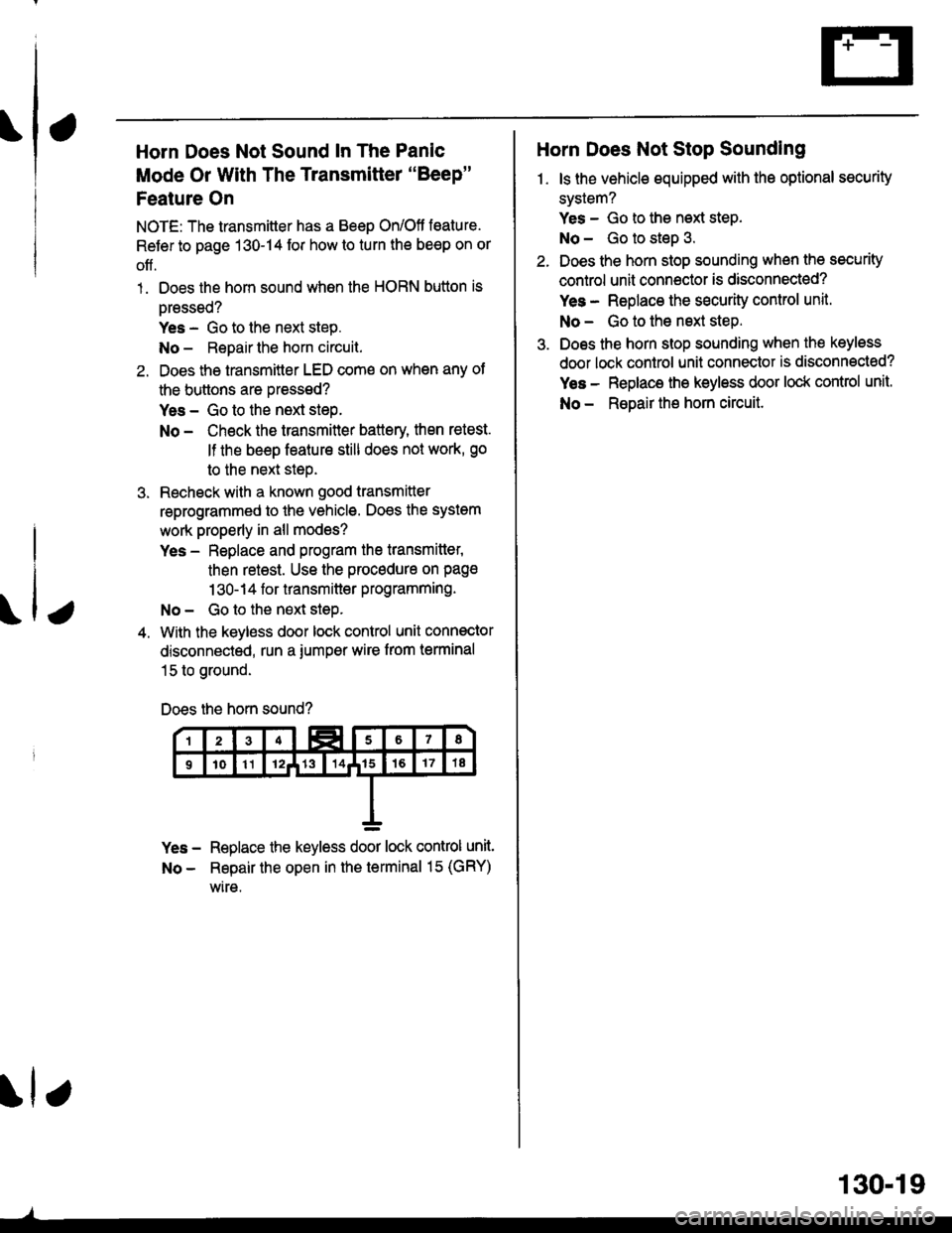
Horn Does Not Sound In The Panic
Mode Or With The Transmitter "Beep"
Feature On
NOTE: The transmitter has a Beep On/Ott toature.
Refer to page 130-14 for how lo turn the be€p on or
off.
1. Does the horn sound whon the HORN button is
oressed?
Yes - Go to the next step.
No - Repair the horn circuit.
2. Does the transmitter LED come on when any of
the buttons are Dressed?
Yes - Go to the next steP.
No - Check the transmitter battery, then retest.
lf the beep feature still does not work, go
to the next steo.
3. Recheck with a known good transmitter
reprogrammed to the vehicle. Does the system
work properly in all modes?
Yes - Replace and program the transmitter,
then retest. Use the procadure on pag€
1 30-1 4 for transmitter programming.
No - Go to the neLt siep.
4. With the keyless door lock control unit connector
disconnected, run a iumper wire from terminal
15 to ground.
Does the horn sound?
Yes - Replace the keyless door lock control unit.
No - Repair the open in th€ terminal 15 (GRY)
wire.
\lr
130.19
Horn Does Not Stop Sounding
1. ls the vehicle equipped with the optional security
system?
Yes - Go to the next step.
No - Go to steD 3.
Does the horn stop sounding when the security
control unit connoctor is disconnected?
Yes - Replace the sEcurity control unit.
No - Go to the nsxt step.
Does the horn stop sounding when the keyless
door lock control unit connector is disconnected?
Yes - Replace the keyless door lock control unit.
No - ReDair the horn circuit.
Page 2055 of 2189
How the Circuit Works
Arming the Security System
The security system can be armed:
r By pressing the remote control LOCK button
(if equipped)
. 20 seconds atter closing all doors (C)UDX only)
Arming with the Transmitter
The security system can be armed by removing the
ignition key from the ignition switch, closing all
doors and the trunk, and pressing the LOCK button
on the transmitter. When you arm the system in this
way, the remote control LED comes on, the status
LED flashes once per second, the parking lights
flash once. the doors lock. and the horn sounds
once if the beeo sound mode is on.
Passive Arming (CX and Dx only)
When you turn the ignition to OFF, remove the
ignition key from the ignition switch, and close all
the doors and the trunk; the system will
automatically arm itself 20 seconds after the trunk
or last door is closed. When you arm the system
this way, the status LED tlashes 4 times per second
during the exit delay time, and once per second
after the system is armed; the parking lights will
flash once to confirm that the system is armed.
Triggering the Alarm
Atter you've armed the system, it will trigger the
alarm if any door or the trunldhatch is opened. lf the
battery is disconnected when the system is armed or
in the alarm mode, reconnecting it will immediately
trigger the alarm. When the alarm is triggered, the
following will occur for 30 seconds:
. the horn sounds
o the parking lights flash once per second
. the status LED flashes hvice oer second
. the starter is disabled
After 30 seconds, the alarm will stop and the
system will rearm. Pressing the transmitter
UNLOCK button will disarm the svstem.
tlr
133-13
Disarming the System without the Remote
Transmitter (HX, LX, and EX)
You can disarm the system by turning the ignition
switch to ON (ll) and pressing the disarm/valet
switch on the right side ol the stereo tuner face. The
disarm switch will also disarm the svstem after the
system has been triggered.
Disarming the System with the Remote
Transmitter (Hx, Lx, Ex, DX-V, and Si)
Pressing the transmitter UNLOCK button will disarm
the system. The parking lights llash t\ivice if the
alarm has not been tnggered. The parking lights
flash three times if the alarm has been triggered.
The driver's door will unlock. lf you press the unlock
button twice, it will unlock all doors. lf a door is not
opened within 30 seconds, the system will lock all
doors and rearm.
Disarming the System (CX and DX only)
lf the system arms itself, there is a 20 second delay
after you open a door before the alarm will trigger.
To disarm the system in this mode, simply turn the
ignition switch to the ON position
ldentitying Tripped Sensors
The system identifies which sensor trips the alarm
by flashing the status LED. To display the trip
sensor flash code, press the disarm/valet switch 3
times within 5 seconds after the system has been
disarmed. The status sensor will blink according to
the followino codes:
SensorsNumber of Flashes
Door
TrunldHatch
System Switches
1 blink, pause, repeat
2 blinks, pause, repeat
3 blinks, pause, repeat
For further operating instructions, see the security
syslem owner's manual.
(cont'd)
Page 2087 of 2189

37. Top Right Side of D16Y7 Engine
Component Location
J\
40. Front of D16Y5 Engine (D1685/D16Y7 Similar)\,
38. Top Center of Engine (except Dl685)41. Front of Dl6Y5 Engine (DI685/D16Y7 Similar)
39. Right Rear of Engine Compartment42. Front of Dl6Y8 Engine ('96-'98)
201 -6
t