2000 HONDA CIVIC ACC unit
[x] Cancel search: ACC unitPage 1142 of 2189
Front Damper
Disassembly/lnspection
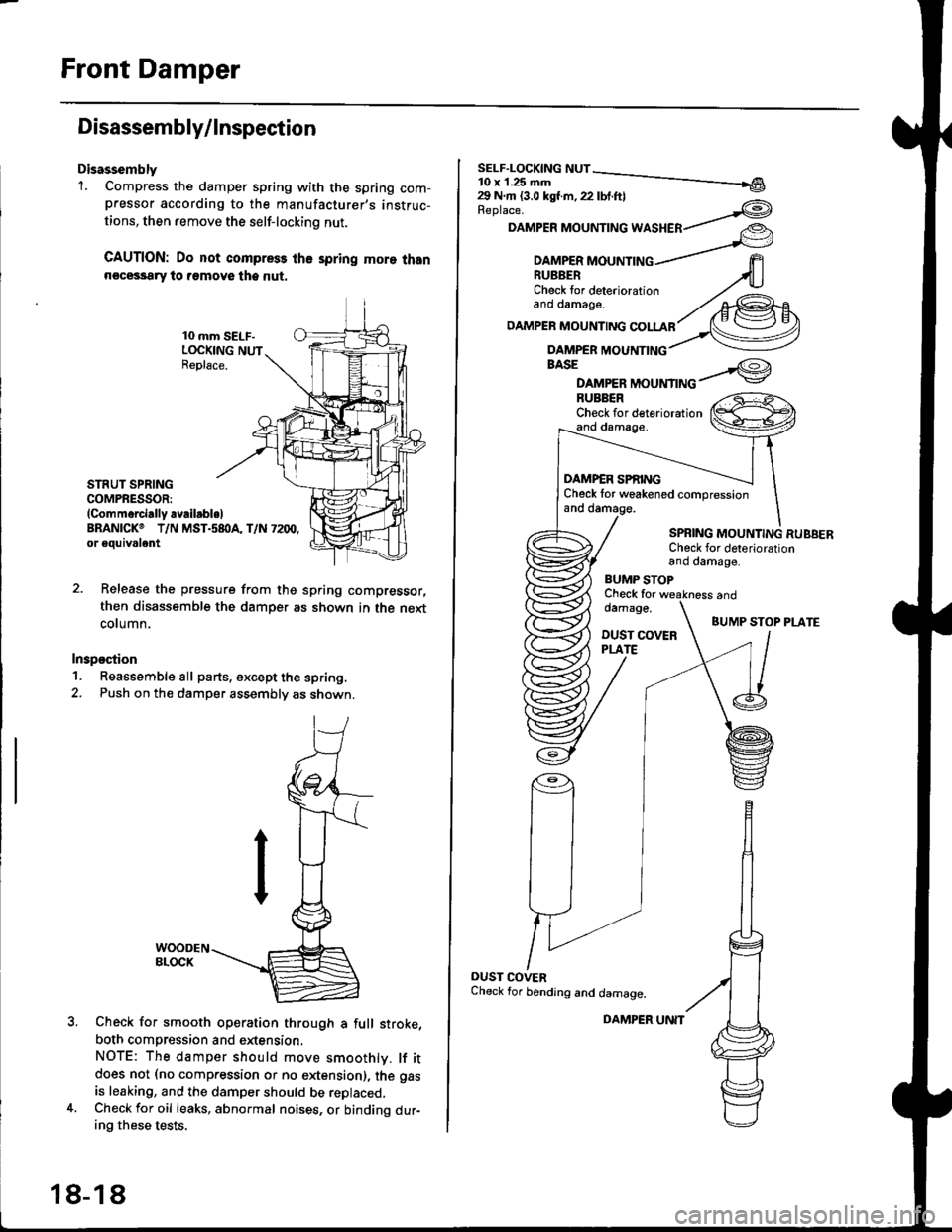
Disassembly'1. Compress the damper spring with the spring com-pressor according to the manufacturer,s instruc-
tions, then remove the self-lockino nut.
CAUTION: Do not compress the spring more thann€cessary to remove the nut.
10 mm SELF-LOCKING NUTReplace.
STRUT SPRINGCOMPRESSOR:(Commerci.lly availabl.lBRANICKO T/N MST.s8I}A, T/N 7200,or eouivalent
Release the pressure from thg spring compressor,
then disassemble the damper as shown in the next
column.
Inspostion
1. Reassemble all parts, except the spring.
2. Push on th€ damper assembly as shown.
Check for smooth operation through a full stroke,
both compression and extension,
NOTE: The damper should move smoothlv. lf itdoes not (no compression or no extension), the gas
is leaking, and the damper should be replaced.Check for oil leaks, abnormal noises, or binding dur-ing these tests.
18-18
DAMPER UNIT
Replace.
DAMPER MOUNTING WASHER
BASE
DAMPER MOUNTINGBUBBERCheck for deteriorationand damage.
DAMP€R SPf,INGCheck tor weakened compressionand damage.
SPBING MOUNTING RUBBERCheck for deteriorationand damage,
BUMP STOPCheck fordamage.
DUST COVERPLATE
and
BUMP STOP PLATE
OUST COVERCheck for bending and damage.
Page 1149 of 2189
T
11.
1)
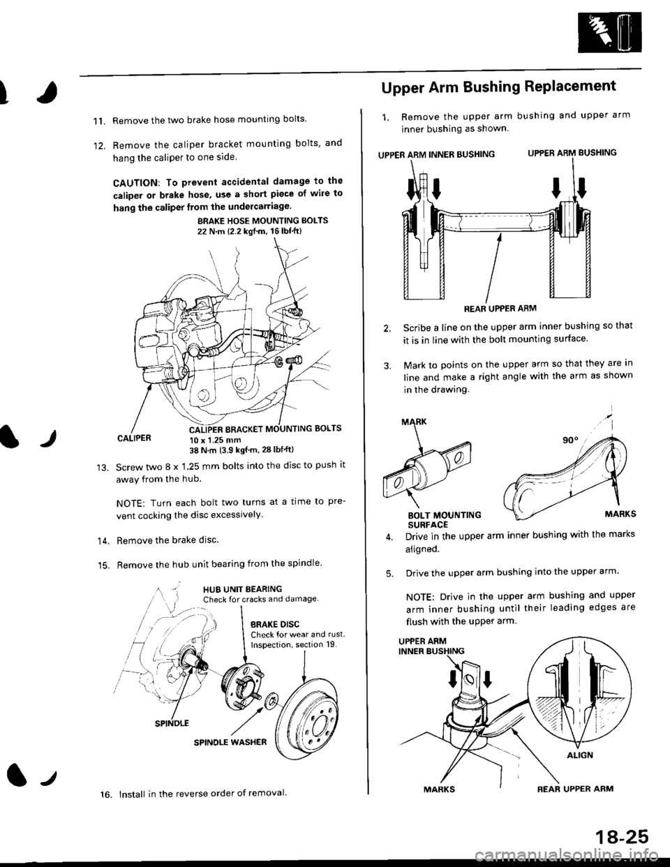
Remove the two brake hose mounting bolts
Remove the caliper b.acket mounting bolts, and
hang the caliPer to one side
CAUTION: To prevent accidental damage to the
caliper or brake hose, use a short piece of wile to
hang the caliper from the undercarriage.
BRAKE HOSE MOUNTING BOLTS
22 N'm {2.2 kgf'm, 16lbt"ft}
CALIPER 10 x 1.25 mm38 N'm (3.9 kgf'm, 28 lbf'ftl
Screw two 8 x 1.25 mm bolts into the disc to push it
away from the hub.
NOTE: Turn each bolt two turns at a time to pre-
vent cocking the disc excessively.
Remove the brake disc.
Remove the hub unit bearing from the spindle
SPINOLE WAS}IER
lr
14.
15.
lt
16. lnstall in the reverse order of removal.
1A-25
Upper Arm Bushing RePlacement
1. Remove the upper arm bushing and upper arm
jnner bushing as shown
UPPER ARM INNER BUSHING UPPER ARM BUSHING
REAR UPPER ARM
Scribe a line on the upper arm inner bushing so that
it is in line with the bolt mounting surface
Mark to points on the upper arm so that they are In
line and make a right angle with the arm as shown
in the drawing.
BOLT MOUNTINGSURFACE
Drive in the upper arm inner bushing with the marks
aligned.
Drive the upper arm bushing into the upper arm
NOTE: Drive in the upper arm bushing and upper
arm inner bushing until their leading edges are
flush with the uPPer arm
ttI
5.
UPPER ARM
Page 1202 of 2189
L
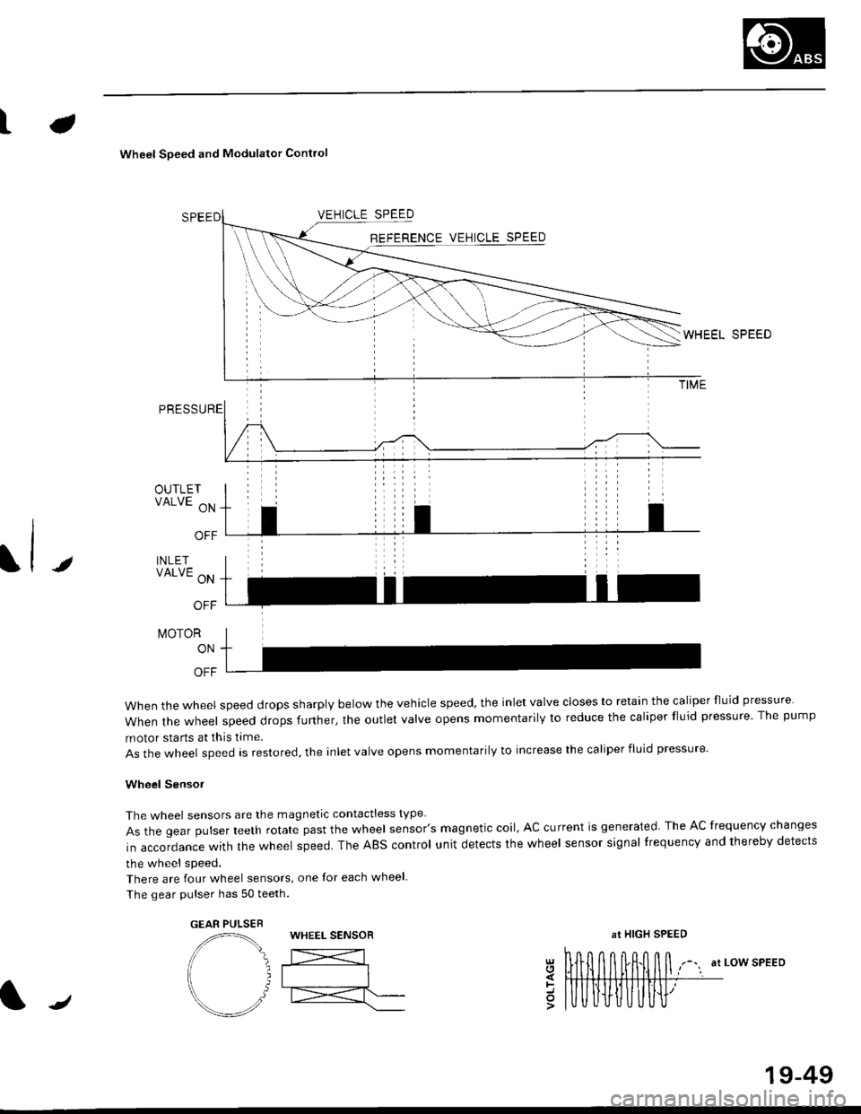
Wheel Soeed and Modulator Contlo
t
OUTLETVALVE ON
OFF
INLETVALVE ON
OFF
t\,40ToR
ON
OFF
when the wheel speed drops sharply below the vehicle speed, the inlet valve closes to retain the caliper fluid pressure
When the wheel speed drops further, the outlet valve opens momentarily to reduce the caliper fluid pressure. The pump
motor starts at this time.
As the wheel speed is restored, the inlet valve opens momentarily to increase the caliper fluid pressure.
Wheel SensoJ
The wheel sensors are the magnetic contactless type
As the gear pulser teeth rotate past the wheel sensor's magnetic coil, AC current is generated The AC frequency changes
in accordance with the wheel speed. The ABS control unit detects the wheel sensor signal frequency and thereby detects
the wheel speed.
There are four wheel sensors, one for each wheel
The gear pulser has 50 teeth.
EEL SPEED
at LOW SPEEDgl
=o
GEAR PULSEBWHEEL SENSOBat HIGH SPEED
/
19-49
Page 1208 of 2189
tJ
t\
Kickback
1. The motor operates when the ABS is functioning, and the fluid in the reservoir is forced out to the master cylinder
causing kickback at the brake pedal.
2. TheABScontrol unit operates the solenoid valve when the brake pedal is released afterthe initial diagnosis Youmay
hear the faint solenoid valve operation sound at this time. but it is normal.
Pump Motor
1. The pump motor operates when the ABS is functioning
2. The ABS control unit checks the pump motor operation during acceleration. You may hear the faint operation sound
at this time. but it is normal.
Brake Fluid Replacament/Air Blsading
1. Brake fluid replacement and air bleeding procedures are the same as for conventional brakes
Troubleshooting
1. The troubleshooting flowcharts explain the procedures on the assumption that the cause of the problem is still pre-
sent and the ABS indicator light is still on.
Note that troubleshooting following the flowchart when the ABS indicator light does not come on can result in incor-
rect judgment.
2. Ouestion the customer about the conditions when the problem occurred, and try to reproduce the same conditions
for troubleshooting.
self,diagnosis is made at various times such as the initial diagnosis, except ABS control. during ABS control, during
acceleraiion, during the specified vehicle speed, etc. Therefore, the symptom cannot be checked unless the check
conditions match with the problem conditions
3. When the ABS indicator light does not come on during the test drive, but the troubleshooting is performed based on
the DTC, check for the loose connectors. poor contact of the terminals, etc, before troubleshooting.
4. After troubleshooting, erase the DTC and test-drive the car. Be sure that the ABS indicator light does not come on.
5. The connector illustrations show the female connectors with a single outline and the male connectors with a double
ouflrne.
6. The connector terminal cavities containing female terminals are always numbered by looking at the connector from
the wire side. and the cavities containing male terminals are always numbered by looking at the connector from the
terminal side.
r'
19-55
Page 1210 of 2189
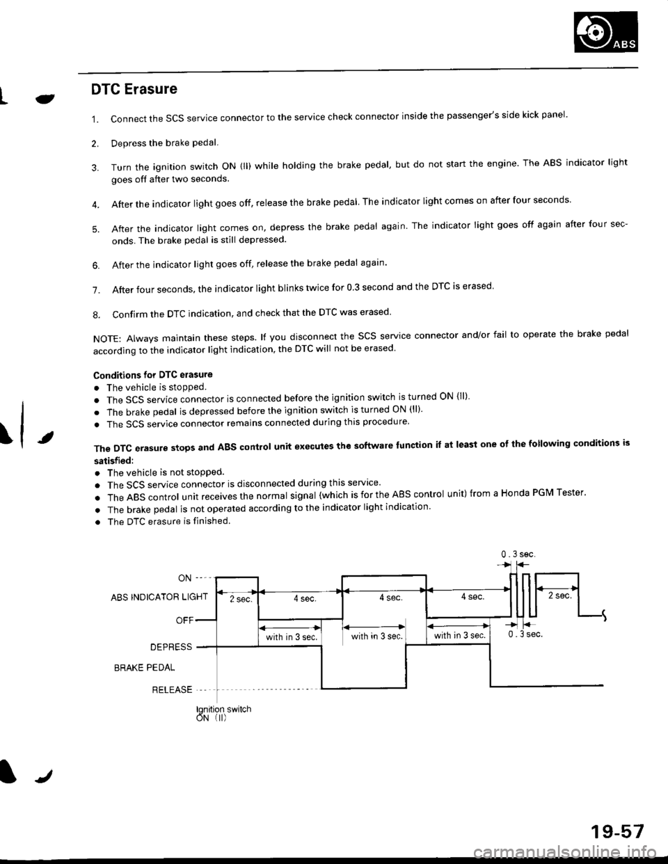
LJDTG Erasure
1.
2.
Connect the SCS service connector to the service check connector inside the passenger's side kick panel.
Depress the brake pedal.
Turn the ignition switch oN (ll) while holding the brake pedal, but do not start the engine. The ABS indicator light
goes off after two seconds.
After the indicator light goes off, release the brake pedal The indicator lightcomeson after four seconds
After the indicator light comes on, depress the brake pedal again. The indicator light goes off again after four sec-
onds. The brake pedal is still depressed.
4.
5.
\t
6. After the jndicator light goes off, release the brake pedal again'
7. After four seconds, the indicator light blinks twice for 0 3 second and the DTC is erased
8. Confirm the DTC indication, and check that the DTC was erased
NOTE: Always maintain these steps. lf you disconnect the scs service connector and/or fail to operate the brake pedal
according to the indicator light indication, the DTC will not be erased
Conditions for DTC erasure
o The vehicle is stopped.
. The SCS service connector is connected before the ignition switch is turned ON {ll)
. The brake pedal is depressed before the ignition switch is turned ON (ll)'
. The SCS service connector remains connected during this procedure
The DTC erasure stops and ABS control unit executes the software lunction it at least one ot the following conditions is
satisfied:
o The vehicle is not stopped.
. The SCS service connector is disconnected during this servace'
.TheABscontro|unitreceivesthenormaIsigna|(whichisfortheAEscontro|unit)fromaHondaPGMTester'
. The brake pedal is not operated according to the indicator light indication
. The DTC erasure is finished
ABS INDICATOR LIGHT
OFF
DEPRESS
BRAKE PEDAL
RELEASE
0.3sec
lqnition switchoN (I)
J
19-57
Page 1509 of 2189
D
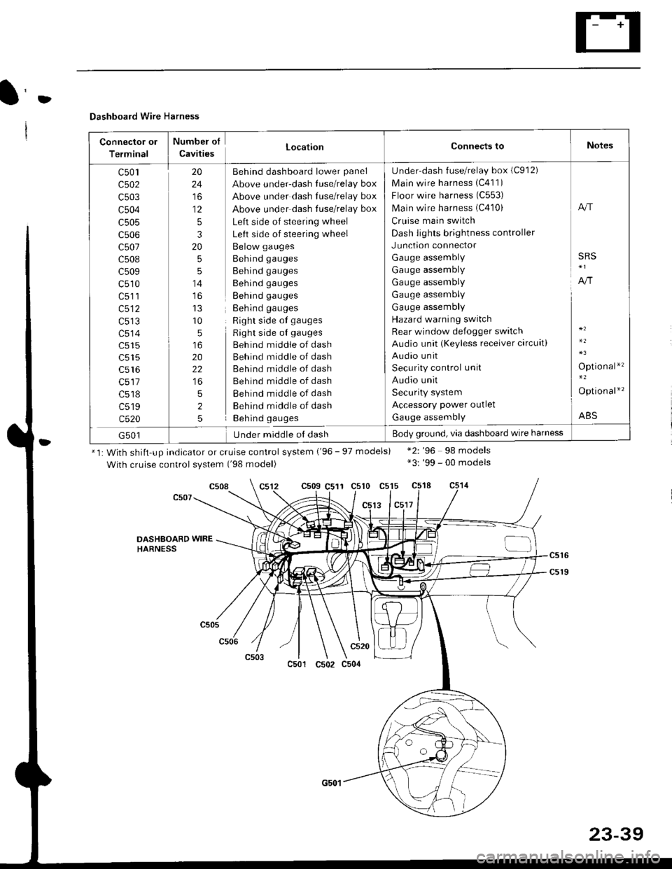
Dashboard Wire Harness
Connector ol
Terminal
Numbel of
CavitiesLocationConnects toNotes
c501
c502
c503
c504
c505
c507
c508
c509
c510
c513
c514
c515
c516
c518
c519
c520
20
24
to
12
5
3
20
5
5
14
r0
5
20
22
5
2
5
Behind dashboard lower panel
Above under-dash luse/relay box
Above under dash Iuse/relay box
Above under dash tuse/relay box
Left side of steering wheel
Left side of steering wheel
Below gauges
Behind gauges
Behind gauges
Behind gauges
Behind gauges
Behind gauges
Right side ot gauges
Right side oI gauges
Beh ind middle of dash
Behind middle of dash
Behind middle of dash
Behind middle of dash
Behind middle of dash
Behind middle of dash
Behind gauges
Under-dash {use/relay box (C912)
Main wire harness 1C411)
Floor wire harness (C553)
Main wire harness (C410)
Cruise main switch
Dash lights brightness controller
Junction connector
Gauge assembly
Gauge assembly
Gauge assembly
Gauge assembly
Gauge assembly
Hazard warning switch
Rear window defogger switch
Audio unit (Keyless receiver circuit)
Audio unit
Security control unit
Audio unit
Security system
Accessory power outlet
Gauge assembly
A"r
SRS
A,/r
Optio nal*'�
Option al*'�
ABS
G501Under middle ol dashBody ground, via dashboard wire harness
*1: With shiit-up indicator or cruise control system ('96 - 97 models)
With cruise control system ('98 model)
c509 C511 c510 c515
13 lc5l7
*2: '96 98 models*3: '99 - 00 models
c508
DASHSOARD WIREHARNESS
c501
c520
c502 c504
23-39
Page 1535 of 2189
lr-
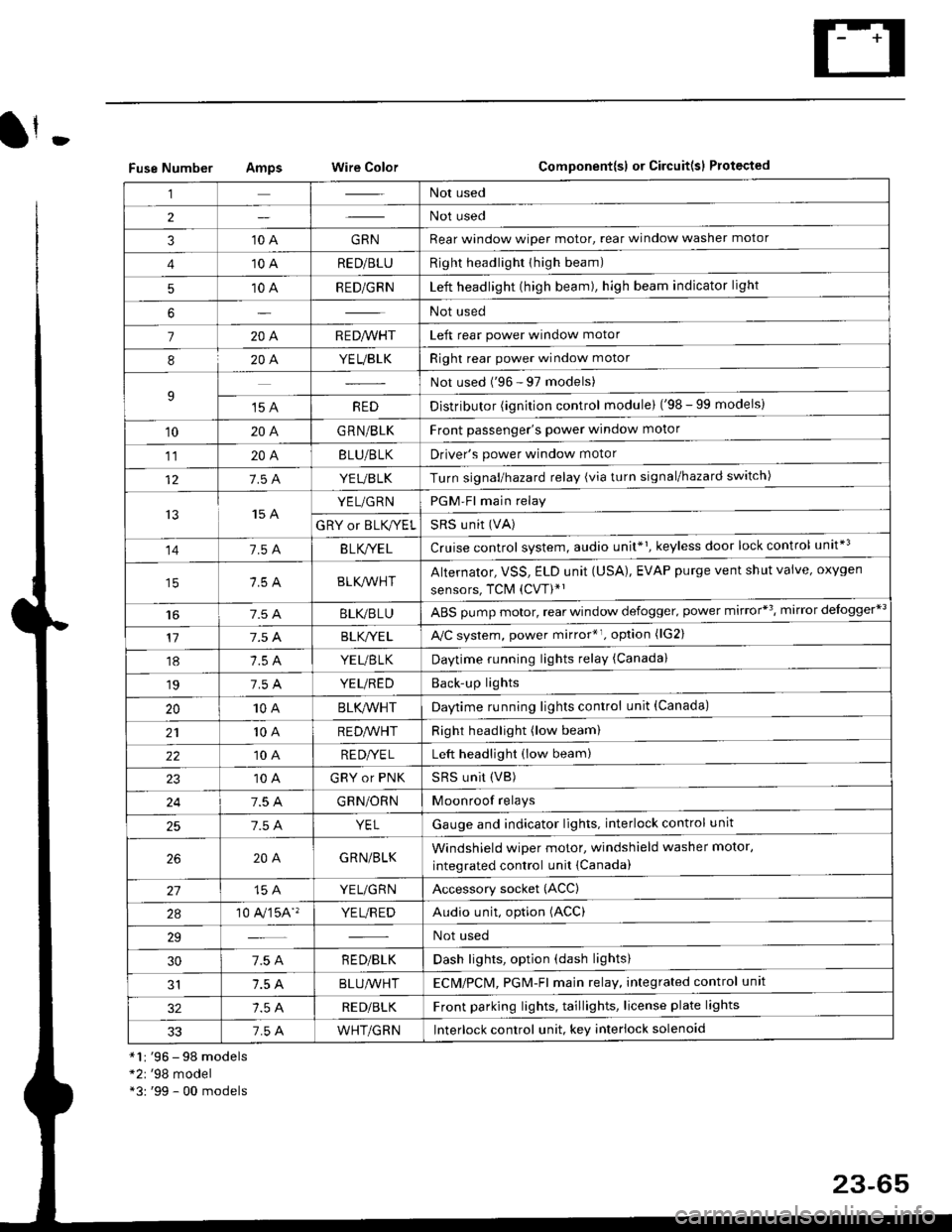
Fuse NumberAmpswire ColorComponent{sl or Circuit(sl Protected
*1r '96 - 98 models*2r '98 model*3: '99 - 00 models
,lNot used
2Not used
310 AGRNRear window wioer motor, rear window washer motor
410 ARED/BLURight headlighr thigh beam)
510 ARED/GRNLeft headlight (high beam), high beam indicator light
6Not used
7204R E D/VVHTLeft rear power window motor
820A.YEUBLKRight rear power window motor
9Not used ('96 - 97 models)
't5 AREDDistributor (ignition control module) ('98 - 99 models)
10204G RN/BLKFront passenger's power window motor
1120ABLU/BLKDriver's power window motor
127.5 AYEUBLKTurn signal/hazard relay (via turn signal/hazard switch)
t515 AYEL/GRNPGM-Fl main relay
GRY or BLK,^/ELSRS u nit (VA)
141.54B LK/YE LCruise control system, audio unit*1, keyless door lock control unit*3
BLK/lr'r'HTAlternator, VSS, ELD unit (USA), EVAP purge vent shut valve, oxygen
sensors, TCM (CVT)*'
t6BLI(,/BLUABS pump motor, rear window defogger. power mirror*3, mirror delogger*3
177.5 ABLK,/YE LA,/C system, power mirror*r. option (lG2)
18YEUBTKDaytime running lights relay (Canada)
197.5 AYEUREDBack'up lights
2010ABLK/VVHTDaytime running lights control unit (Canada)
2110 AREDA/VHTRight headlight (low beam)
2210 ARE DI/E LLeft headlight (low beam)
10 AGRY or PNKSRS UNit (VB)
247.5 AGRN/ORNMoonroof relays
257.5 AYELGauge and indicator lights. interlock control unit
204GRN/BLKWindshield wiper motor, windshield washer motor,
integrated control unit {Canada)
15 AYEL/GRNAccessory socket (ACC)
2a10 A,/'�]5A''YE L/R EDAudio unit, option (ACC)
29Not used
307.5 AR ED/BLKDash lights, option (dash lights)
1.5 ABLUA/VHTECM/PCl\4, PGM-Fl majn relay, integrated control unit
RED/BLKFront parking lights, taillights, license plate lights
337.5 AWHT/GRNlnterlock control unit. key interlock solenoid
23-65
Page 1539 of 2189
t
BLI(BLU - ABS controlunit
r 96'9€ models: 99 modol: GRY (96-97 models: GRN (9&00 models
Rear window d8loloer swilch indicalo. l€ht
::: ) mirroa d€loQor r?Hrgn, Ma miror i;logger sYritch)
Miror dolog06r $ tdr indicalor lighl'2
191 ) oo*e, ri,,o, "qraor',hEn, ivra pow mircr sMdr
odional conna.ior 1lG2)
*2*3
REAR WINDOW DEFOGGER RELAY{Via Gar wndow deloggot sw ch)fro page 23-71 )
N0.42 (40A)FUSE(Frofir page 23.67)
WHTi BLK
t
lFusdrelay bor socl(el)WHT/BLK
I
V
fro page 23'70)
Ipag6 23-0o
. BLOWER MOTOR FELAY. CONDETISER FAN RETAY. ,VC COMPRESSORCLWCH RELAY. NAONTOR FAN RELAY0o pag€ 2368)
12)Heal€r conlrol Pan6l,ryC her|lDshlMode conlrol molorReorolalion conlol molorAow€r molor iEh aelay
YEUBLK -
YEUGRN -
:rl l^r A k/YF l -
B./"|YEL - Ctr|s€ conlrcl Jn (Via main swildr)
l- C'uEe ma'4 swildr 'ndicalot lEhlL Audio unil (K€y oss rece'ver drol4)
BLKryEL - Kevless door tock conlroi unit
UNDER.DASH FUSE/RELAY BOX
N0.16 (7.5A)
(To page 23'70)
No.l2 (7.5A)
N0.13 (15A)
N0.14 (7.54)
IGN TION SWITCH
BA1 ;.'
1 '.._ ACC
q, (/vrr - |.fi II ::: I mrcr mircr aqua|ol'r
F DAY'IME FUNNING LIGHISvELrtsLK -113> CONTFOL UN|T (Ceneda)t'- (f o We 23-71)
,F1J- ,n*,"',
'96-97 mod6ls
""j
'98-99 models
GRN -
GRN _
Rear window washer molof
Rear window wiper molor
Turn srgnal/hazard relay(Viaswilch)
PGM-Flmain relay
SRS unii (VA)
(cont'd)
23-69