2000 HONDA CIVIC Ignition system
[x] Cancel search: Ignition systemPage 555 of 2189

Emission Control System
(From page 11 285)
Check lor an op€n in the wire{PCS line}:1. Turn the ignition switch OFF.2, Reconnect the 2P connector lothe EVAP purge control sole-noid valve.3. Turn the ignition switch ON (lll.4. Measure vo ltage betweenECM/PCM connector terminals415 and A]0.
Repai. op€n in the wire bGtweenthe EVAP purge control solenoidvalve and the ECM/PCM {A151.
Substitute a known-good ECM/PCM and retest. tf sympiom/indi-cation goes away, replac6 theoriginal ECM/PCM.
Evaporative Emission (EVAPI Controls (cont'd)
(From page 11'285)
(To page 'l1 287)
\.
ECM/PCM CONNECTOR A {32P}
PCS{RED/YEL)
PGl
{BLK)
Wire side oftemaleterminals
EVAP BYPASSSOLENOID VALVE
O.RINGBeplace.
PUMP/GAUGE,0 - 30 in.HgA973X -
041 -
xxxxx
EVAP TWO WAY VALVE
EVAP IWO WAY
Check the EVAP two way valvo:See EVAP two way valve test (seepage 11'294).
Replace tho EVAP two way valve.
Check the EVAP bypr$ 3olenoid
1. Disconnect the vacuum hosefrom the EVAP two way valveand connect a vacuum pumpto the hose.2. Turn the ignition switch ON lll).3. Apply vacuum to the hose.Check tor a short in the wire{2WBS linel:Disconnect the 2P connector fromthe EVAP bypass solenoid valve.Does the valve hold vacuum?
Repair short in the wire betwe€nEVAP bypass sol€noid valve andrhe ECM/PCM lA28).
Does the valve hold vacuum?
11-286
Page 557 of 2189
Emission Control System
Evaporative Emission {EVAP) Controls (cont'dl
\J
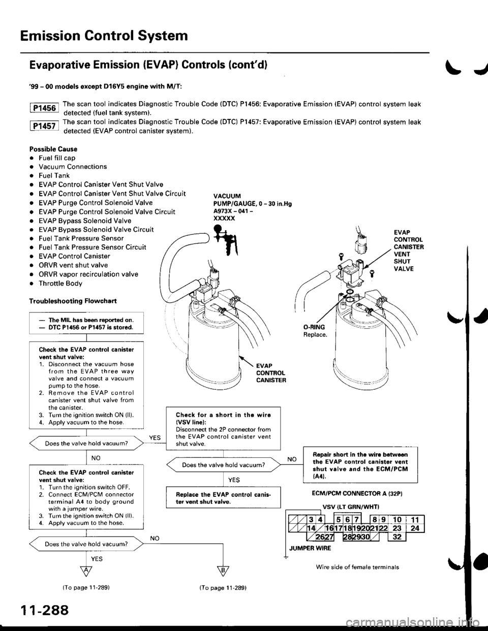
tF1456-l
tP14sz-l
EVAPCONTROLCANISTERVENTSHUTVALVE
O.RINGReplace.
EVAPCONTROLCANISTER
ECM/PCM CONNECTOR A I32PI
(To page 11'289)
'99 - 00 modols except Dl6Y5 engine with M/T:
The scan tool indicates Diagnostic Trouble Code (DTC) P1456: Evaporative Emission (EVAP) control system leak
detected (fuel tank svstem).
The scan tool indicates Diagnostic Trouble Code (DTC) P1457: Evaporative Emission (EVAP) control system leak
detected (EVAP control canister system).
Possible Cause
. Fuel fill cap
. Vacuum Connections
. FuelTank
. EVAP Control Canister Vent Shut Valve
. EVAP Control Canister Vent Shut Valve Circuit
. EVAP Purge Control Solenoid Valve
o EVAP Purge Control Solenoid Valve Circuit
. EVAP Bypass Solenoid Valve
0 -30 in,Hg
. EVAP Bypass Solenoid Valve Circuit
. Fuel Tank Pressure Sensor
. Fuel Tank Pressure Sensor Circuir
. EVAP Control Canister
. ORVR vent shut valve
. ORVR vapor recirculation valve
. Throttle Body
Troubleshooting Flowchart
VACUUMPUMP/GAUGE,A973X - oal -
xxxxx
T-t
t\
The MIL has been reported on.DTC P1456 o. P1457 is stored.
Check the EVAP cont.ol canistervent shul valve:1. Disconnect the vacuum hosefrom the EVAP three wayvalve and connect a vacuumpump to the hose.2. Remove the EVAP controlcanister vent shut valve fromtne canrster.3. Turn the ignition switch ON (ll).
4. Apply vacuum to the hose.Check for a short in the wiro(VSV linel:Disconnect the 2P connector fromthe EVAP control canister ventDoes the vaive hold vacuum?
RoDair 3hort in the wire botwe€nthe EVAP control canilter ventshut valve and the ECM/PCM{A4t.
Does the valve hold vacuum?Check the EVAP cont.ol canisterv€nl shut valve:1. Turn the ignition switch OFF.2. Connect ECM/PCM connectorterminal A4 to body groundwith a jumper wire.3. Turn the ignition switch ON (ll).
4. Apply vacuum to the hose.
Reolace the EVAP control canis-ter veni shut valve.
Does the valve hold vacuum?
Wire side of female terminals
11-288
lTo page 11-289)
Page 559 of 2189

Emission Control System
Ch€ck the EVAP purge controlsolenoid valv6:1. Disconnect the 2P connectorfrom the EVAP purge controlsolenoid valve.2. Ouickly raise the engine speedto 3,000 rpm.
Insped vacuum hose routing.lf OK. roplace the EVAP purge
control solonoid valve.
Chock tor r short in the wir€
{PCS line):1. Turn the ignition switch OFF.2. Disconnect ECM/PCM connec-tor A (32P).
3- Check tor continuity betweenthe EVAP purge control sole-noid valve 2P connector termi-nal No. 2 and body ground.
Check the vacuum when hot:1. Turn the ignition switch OFF.2. Block the rear wheels and setthe parking brake.3. Jack up the lront of the vehi-cle and support it with safetystands.4. Start the engine. Hold theengine at 3,000 rpm with noload (in Park or neutrali until
the radiator fan comes on, thenlet it idle.5. Check for vacuum at the vac-uum hose with transmissionin gear (A/T in E position,
lvl/T in 1st gear) after startingthe engine.6. Ouickly raise the engine speedto 3,000 rpm.
Rooair shoft in the wire belwegnthe EVAP pulg6 control solenoidvalvs and tho ECM/PCM {A61.ls there continuity?
Substitute a known-good ECM/PCM and rech6ck. lt 3ymptom/indicrtion 90e3 rway, r6plac6 th€o.iginal ECM/FCM.
Check th€ EVAP purge controlsolenoid valve:1. Turn the;gnition switch OFF.2. Disconnect the 2P connectorfrom the EVAP purge controlsolenoid valve and warm itup to normal operating tem-perature again if necessary.3. Start the engine.4- At the harness side, measurevoltage between the EVAPpurge control solenoid valve2P connector terminal No. 1and No.2 with the transmis-sion in gear {A/T in E posi-tion, M/T in lst geari.
In3pect vacuum hoae routing.lf OK, repl.ce EVAP purge con-trol solonoid valve.ls there battery voltage?
Chock for an open in the wire(lG1 lina):At the harnoss side, measure volt-age beNveen the EVAP purge con-trol solenoid valve 2P connectorterminal No. 1 and body ground.
Repair open in the wire b€lwe€nEVAP purge contrl 3olenoid valv6and lhe No. 15 ALTERNATOR SPSENSOR 17.5 A, fu3e.
ls there battery voltage?
Evaporative Emission (EVAPI Controls (cont'dl
(From page 11-289)
(To page 11-291)
11-290
IJ
EVAP PURGE CONTROL SOLENOIDVALVE 2P CONNECTOR IC114I
PCS
IRED/YEL)
temaletermrnars
of
PCS(RED/YEL)
tGlIBLK/YEL)
{To page 11 291)
Page 561 of 2189

Emission Control System
Evaporative Emission (EVAPI Gontrols (cont'd)EVAP BYPASSSOLENOID VALVEY
(From page l1'291)
Check for a short in the wire{2WBS linel:Disconnect the 2P connector {romthe EVAP bypass solenoid valve.
Does the valve hold vacuum?
Repair short in the wire betweenEVAP bypass solenoid velve andrhe ECM/PCM {A3).
Ooes the valve hold vacuum?
Check the EVAP bvpr$ 3olenoid
1. Turn the ignition switch OFF.2. Connect ECM/PCM connectorterminal A3 and body groundwith a jumper wire.3. Turn the ignition switch ON (ll).Ch€ck lor an op.n in the wirellcl linol:1. Turn the ignition switch OFF.2. Disconnect the 2P connectorfrom the EVAP bypass sole-noid valve.3. Turn the ignition switch ON (lll.
4, Measure voltage between theEVAP bypass solenoid valve2P connector terminal No. 1and body ground.
Does the valve hold vacuum?
Repair open in the wir6 b€tw€€nEVAP purg6 control 3olanoid valveand the No. 15 ALTERNATOR SPSENSOR {7.5 A) Iuse.
Wire side ol female terminals
EVAP SYPASS SOLENOIOVALVE 2P CONNECTOR IC793}
tG1{BLK/WHT)
Wire side offemaleterminals
{To page 11 293)
11-292
(To page 11 293i
Page 720 of 2189
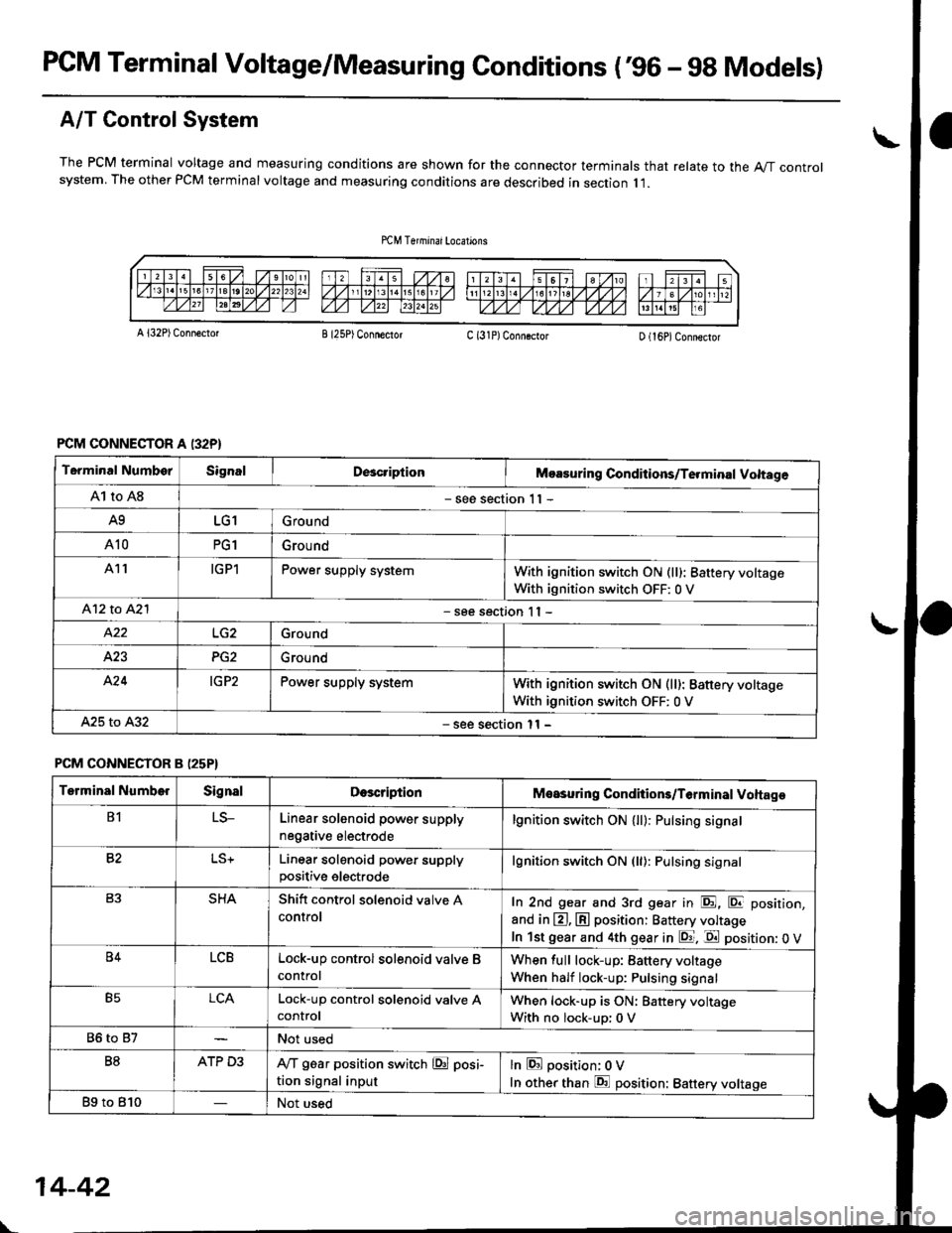
PCM Terminal Voltage/Measuring Gonditions ('96 - 9g Models)
A/T Control System
The PCM terminal voltage and measuring conditions are shown for the connector terminals that relate to the A"/T controlsystem. The other PCM terminal voltage and measuring conditions are described in section I l.
A l32P) Conn€ctotB I25P) ConnectorC (31P)ConngctorD (16P)Connector
PCM CONNECTOR A I32P}
Terminal NumborSignalDcacriptionMoasuring Conditions/Te.minal Voltage
A1 to A8- see section 1 I -
A9LG1Ground
A10PG1Grou nd
A11IGPlPower supply systemWith ignition switch ON (ll): 8attery voltage
With ignition switch OFF: 0 V
412 to A2l- see section I I -
Ground
423PG2Ground
A'24IG P2Power supply systemWith ignition switch ON (ll): Battery voltage
With ignition switch OFF: 0 V
A25 to A32- see section l1 -
PCM CONNECTOR B (25P}
Terminal NumberSignalDescriptionMeasuring Conditions/T6rminal Voltage
B1LS-Linear solenoid power supply
negative electrode
lgnition switch ON (ll): Pulsing signa.
82Linear solenoid power supplypositive electrode
lgnition switch ON (ll): Pulsing signal
SHAShitt control solenoid valve A
controlIn 2nd gear and 3rd gear in E, E position,
and in @, @ position: Battery voltage
In lst gear and 4th gear in E. E position: 0 V
B4LCBLock-up control solenoid valve B
control
When full lock-up: Battery voltage
When half lock-up: Pulsing signal
B5LCALock-up control sol€noid valve AcontrolWhen lock-up is ON: Battery voltage
With no lock-up: 0 V
86 to 87Not used
B8ATP D3IVT g6ar position switch @ posi-
tion signal input
lnEposition; OV
In other than E position: Battery voltage
Bg to 810Not used
\-
14-42
Page 721 of 2189
I
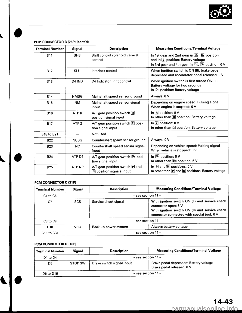
PCM CONNECTOR B {25P1 {cont'dl
Terminal NumberSignalDescriptionMeasuring Conditions/Terminal Vohage
811SHBShift control solenoid valve B
control
In 1st gear and 2nd gear in -q1, q11 position,
and in E] position: Battery voltage
In 3rd gear and 4th gear in lD.J, [Dr- position: 0 V
B't2SLUInterlock controlWhen ignition switch is ON (ll), brake pedal
deoressed and accelerator Dedal released: 0 V
813D4 INDD4 Indicator light controlWhen ignition switch is first turned ON (ll):
Battery voltage for two seconds
In E position: Baftery voltage
B't 4NMSGMainshaft speed sensor groundAlways: 0 V
E tcNMMainshaft speed sensor signal
input
Depending on engine speed: Pulsing signal
When engine is stopped: 0 V
816ATP RAy'T gear position switch Eposition signal input
InE position: 0V
In other than E position: Battery voltage
817ATP 2A/T gear position switch E posi-
tion signal input
InE position: 0V
In orher than E position: Battery voltage
818 to 821Not used
s22NCSGCountershatt speed sensor groundAlwaysr 0 V
B�23NCCountershaft speed sensor signal
input
Depending on vehicle speed: Pulsing signal
When vehicle is stopped: 0 V
B�24ATP D4Ay'T gear position switch lor posi-
tion signal input
InEposition:0V
In other than 6 position: 5 V
ATP NPA,/T gear position switch E and
N position signals input
InE and E positions: 0V
In otherthan E and N] positions: Battery voltage
PCM CONNECTOR C {31P)
Terminal NumberSignalDescriptionMeasuring Conditions/Terminal Voltage
Cl to C6- see section 11 -
c1Service check signalWith ignition switch ON (ll) and service check
connector oDen; 5 V
With ignition switch ON (ll) and service check
connector connected with sDecial tool: 0 V
C8 to Cg- see section 11 -
c10VBUBack-up power systemAlways battery voltage
C11 to C31- see section '11 -
PCM CONNECTOR D (16P}
Terminal NumberSignalDescriptionMeasuring Conditions/Terminal Voltage
Dl to D4- see section 11 -
D5STOP SWBrake switch signal inputBrake pedal depressed: Battery voltage
Brake pedal released: 0 V
D6 to D16- see section 1 l -
14-43
Page 724 of 2189
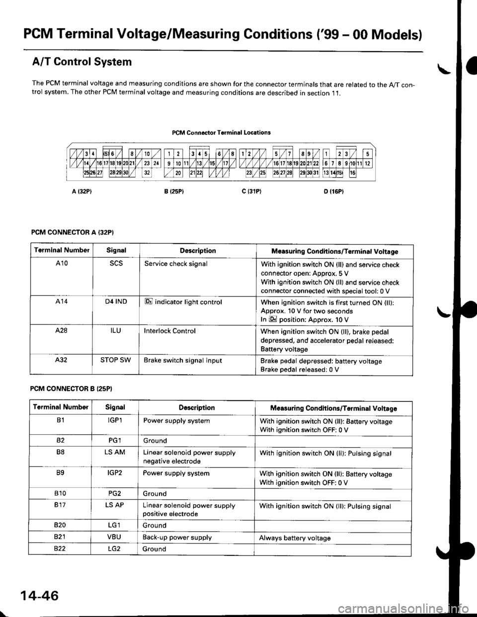
PCM Terminal Voltage/Measuring Conditions ('99 - 00 Models)
A/T Control System
The PCM terminal voltage and measuring condjtions are shown for the connector terminals that are related to the A//T con-trol system, The other PCM terminal voltage and measuring conditions are described in section ,11.
PCM Connoctor Tgrminrl Locations
PCM CONNECTOR A {32PI
PCM CONNECTOR 8 (25P}
Terminal NumbelSignalDescriptionM€asuring Conditions/Terminal Voltage
A105L5Service check signalWith ignition switch ON (ll) and service check
connector open: Approx, 5 V
With ignition switch ON (ll) and service check
connector connected with sDecial tool: 0 V
A14D4 INDE indicator light controlWhen ignition switch is first turned ON (ll):
ApDrox. 10 V for two seconds
In E position: Approx. 1O V
428ILUInterlock ControlWhen ignition switch ON (ll), brake pedal
depressed, and accelerator pedal rereaseo:
Battery voltage
A.32STOP SWBrake switch signal inputBrake pedal depressed: battery voltage
Brake oedal released:0 V
Terminal NumberSignalDescdptionMeasuring Condhions/Torminal Voltag6
B1!GP1Power supply systemWith ignition switch ON (ll): Battery voltage
With ignition switch OFF: 0 V
PGlGround
B8LS AMLinear solenoid power supply
negative electrode
With ignition switch ON (ll): Pulsing signal
B9IG P2Power supply systemWith ignition switch ON (ll): Baftery voltage
With ignition switch OFF: 0 V
810PG2G rou nd
917LS APLinear solenoid power supplypositive electrode
With ignition switch ON (ll): Pulsing signal
B�20Ground
VBUBack-up power supplyAlways battery voltage
822Ground
\
14-46
Page 726 of 2189
Troubleshootin g Procedures
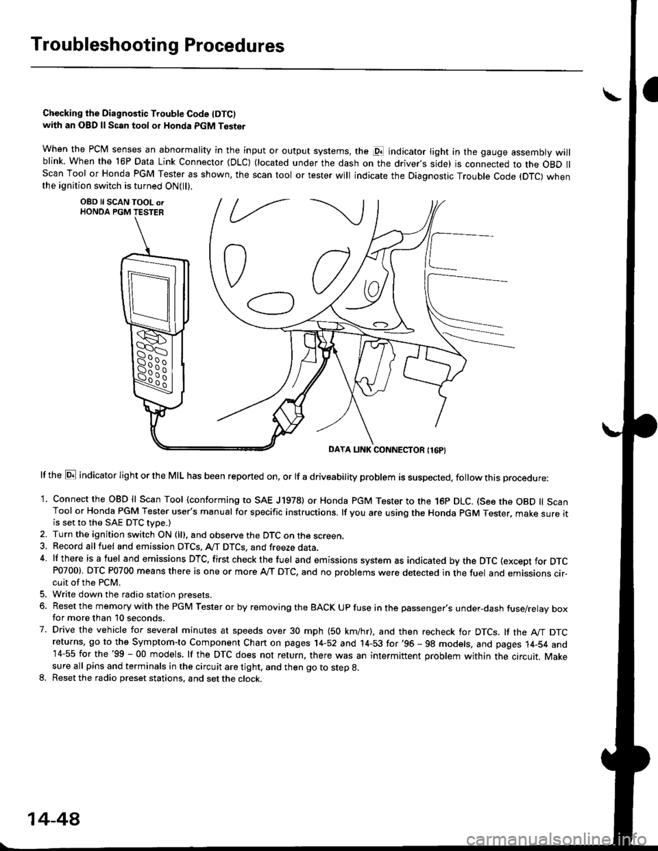
Chccking the Diagnostic Trouble Code IDTC)with an OBD ll Scan tool or Honda PGM Tester
when the PCM senses an abnormality in the input or output systems, the pl indicator light in the gauge assembly willblink. When the 16P Data Link Connector (DLC) (located under the dash on the driver,s side) is connected to the OBD llScan Tool or Honda PGM Tester as shown, the scan tool or tester will indicate the Diagnostic Trouble Code (DTC) whenthe ignition switch is turned ON{ll).
lf the El indicator light or the MIL has been reported on, or lf a driveability problem is suspected, follow this procedure:
1. Connect the OBD ll Scan Tool (conforming to SAE J19781 or Honda PGM Tester to rhe 16p DLC. (See the OBD ll ScanTool or Honda PGM Tester user's manual for specific instructions. lf you are using the Honda PGM Tester, make sure itis set to the SAE DTC type.)
2. Turn the ignition switch ON (lll, and observe the DTC on the screen,3, Record all fuel and emission DTCS, A/T DTCS, and freeze data.4 lf there is a fuel and emissions DTC, first checkthe fuel and emissions system as indicated bythe DTC (except for DTCP0700). DTC P0700 means there is one or more A,/T DTC, and no problems were detected in the fuel and emissions cir-cuit of the PCM.
5. Write down the radio station oresets.
6. Reset the memory with the PGM Tester or by removing the BACK UP fuse in the passenger's under-dash fuse/relay boxfor more than 10 seconds.
7. Drive the vehicle for several minutes at speeds over 30 mph (50 km/hr), and then recheck for DTCS. lf the A"/T DTCreturns, go to the Symptom-to Component Chart on pages 14-52 and 14-53 for'96 - 98 models, and pages 14-54 and14-55 for the'99 - 00 models, lf the DTC does not return, there was an intermittent problem within the circuit. Makesure all pins and terminals in the circuit are tight, and then go to step g.
8. Reset the radio preset stations, and set the clock.
OBD ll SCAN TOOL orHONDA PGM TESTER
DAYA LINK CONNECTOR {16P}
14-44