2000 FORD F150 reset
[x] Cancel search: resetPage 172 of 280

Installing the snowplow
Removing the blocker beam without installing snowplow
attachment hardware may affect air bag deployment in a crash.
Do not operate the truck unless either the blocker beam or snowplow
attachment hardware is installed on the vehicle.
Read the following instructions before installing a snowplow:
²Front GAWR must not exceed 63% of the GVW. Add ballast weight to
the back of the vehicle, if necessary. Refer to the Safety Compliance
Certification Label to find Front GAWR.
²The Front Axle Accessory Reserve Capacity and the Total Accessory
Reserve Capacity listed on the bottom right of the Safety Compliance
Certification Label will determine whether or not the addition of a
snowplow will overload your vehicle.
²The weight of the snowplow and supporting components distributed to
the front axle must not exceed the front accessory reserve capacity.
²The total weight of the snowplow and aftermarket equipment must
not exceed the Total Accessory Reserve Capacity.
²The weight of the installed snowplow and aftermarket equipment must
not load the vehicle beyond the GAWR (front/rear) and GVWR listed
on the Safety Compliance Certification Label.
²The total weight of the snowplow and aftermarket equipment must be
considered part of the payload and must not exceed the Gross
Combined Weight Rating (GCWR) for towing.
²Federal and most local regulations require additional exterior lamps
for snowplow-equipped vehicles. Consult your dealer for additional
information.
²After installing a snowplow to the vehicle, ensure the vehicle's front
toe alignment and front ride height are within specification (reset if
required). These specifications are located in the vehicle's Workshop
Manual. Adherence to the toe, tire pressures and ride height
specification is important for proper tire wear, ride, handling and
headlight aim. Also, maintain the engine oil and transmission fluid
change intervals following the severe duty schedule.
Do not exceed the GVWR or the GAWR specified on the
certification label.
Driving
172
Page 173 of 280

Removing snowplow
Read the following instructions before removing a snowplow:
²After removing a snowplow from the vehicle, ensure the vehicle's front
toe alignment and front ride height are within specification (reset if
required). These specifications are located in the vehicle's Workshop
Manual. Adherence to the toe and ride height specification is
important for proper tire wear, ride, handling and headlight aim.
Snowplowing with your air bag equipped vehicle
Your vehicle is equipped with driver
and passenger air bags. The air bags
are designed to deploy in a collision
with a solid barrier at a range of 13
to 23 km/h (8 to 14 mph) or a
parked car at a range of 25 to 45
km/h (16 to 28 mph).
Careless or high speed driving while plowing snow which results in
vehicle decelerations equivalent to or greater than the air bag
deployment impact speeds listed above can deploy the air bag. Such
driving also increases the risk of accidents.
All occupants of the vehicle, including the driver, should always
properly wear their safety belts, even when an air bag SRS is
provided.
Never remove or defeat the ªtripping mechanismsº designed into the
snow removal equipment by its manufacturer. Doing so may cause
damage to the vehicle and the snow removal equipment as well as
possible air bag deployment.
Do not attempt to service, repair, or modify the Air Bag
Supplemental Restraint System or its fuses. See your Ford or
Lincoln Mercury dealer.
Driving
173
Page 176 of 280

Roadside coverage beyond basic warranty
In the United States, you may purchase additional roadside assistance
coverage beyond this period through the Ford Auto Club by contacting
your Ford or Lincoln Mercury dealer.
Similarly in Canada, you may purchase additional coverage beyond the
basic coverage period by consulting the Ford Roadside Assistance Club
brochure or by calling 1±877±294±CLUB (1±877±294±2582).
HAZARD FLASHER
Use only in an emergency to warn traffic of vehicle breakdown,
approaching danger, etc. The hazard flashers can be operated when the
ignition is off.
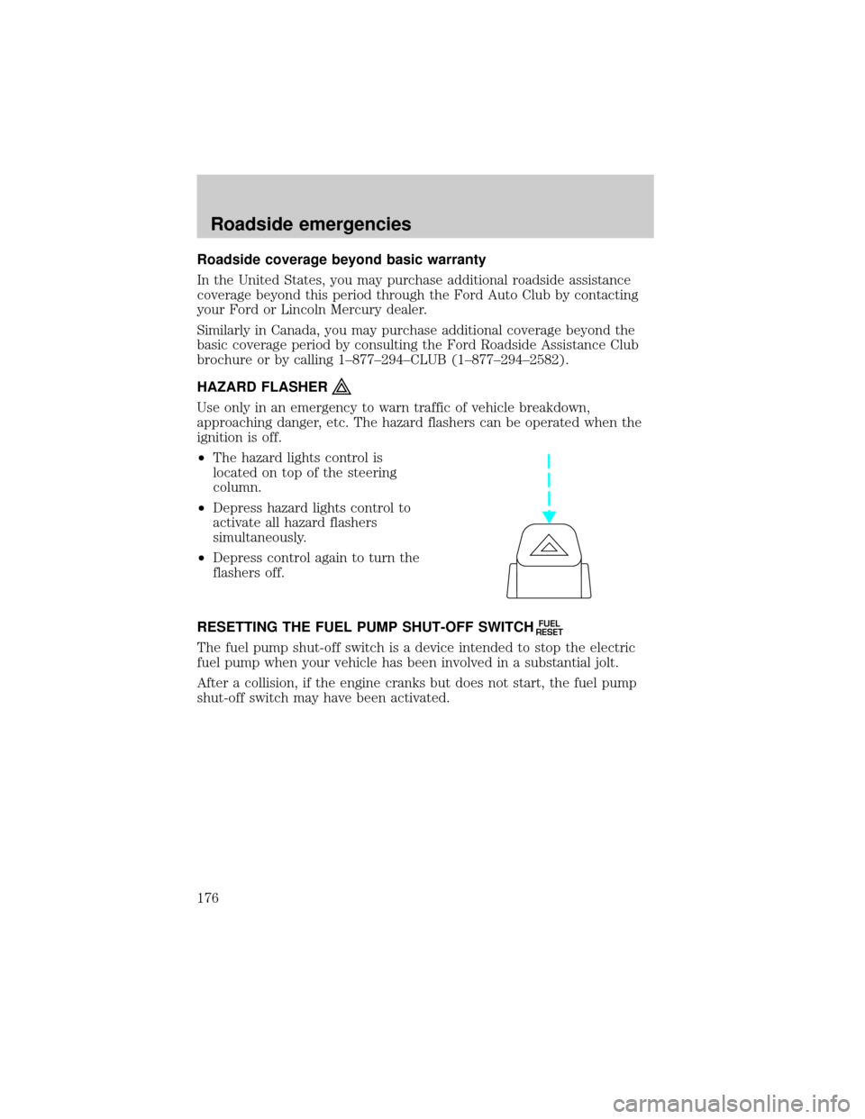
²The hazard lights control is
located on top of the steering
column.
²Depress hazard lights control to
activate all hazard flashers
simultaneously.
²Depress control again to turn the
flashers off.
RESETTING THE FUEL PUMP SHUT-OFF SWITCH
FUEL
RESET
The fuel pump shut-off switch is a device intended to stop the electric
fuel pump when your vehicle has been involved in a substantial jolt.
After a collision, if the engine cranks but does not start, the fuel pump
shut-off switch may have been activated.
Roadside emergencies
176
Page 177 of 280

The fuel pump shut-off switch is
located in the passenger's foot well,
by the kick panel.
Use the following procedure to reset the fuel pump shut-off switch.
1. Turn the ignition to the OFF position.
2. Check the fuel system for leaks.
3. If no fuel leak is apparent, reset the fuel pump shut-off switch by
pushing in on the reset button.
4. Turn the ignition to the ON position. Pause for a few seconds and
return the key to the OFF position.
5. Make a further check for leaks in the fuel system.
FUSES AND RELAYS
Fuses
If electrical components in the
vehicle are not working, a fuse may
have blown. Blown fuses are
identified by a broken wire within
the fuse. Check the appropriate
fuses before replacing any electrical
components.
15
Roadside emergencies
177
Page 211 of 280

Vehicles driven year-round in non-extreme climates should use a 50/50
mixture of engine coolant and distilled water for optimum cooling system
and engine protection.
What you should know about fail-safe cooling (if equipped)
If the engine coolant supply is depleted, this feature allows the vehicle to
be driven temporarily before incremental component damage is incurred.
The ªfail-safeº distance depends on ambient temperatures, vehicle load
and terrain.
How fail-safe cooling works
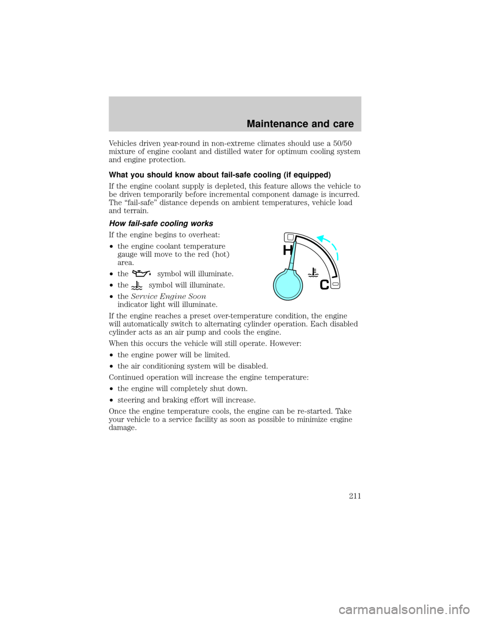
If the engine begins to overheat:
²the engine coolant temperature
gauge will move to the red (hot)
area.
²the
symbol will illuminate.
²the
symbol will illuminate.
²theService Engine Soon
indicator light will illuminate.
If the engine reaches a preset over-temperature condition, the engine
will automatically switch to alternating cylinder operation. Each disabled
cylinder acts as an air pump and cools the engine.
When this occurs the vehicle will still operate. However:
²the engine power will be limited.
²the air conditioning system will be disabled.
Continued operation will increase the engine temperature:
²the engine will completely shut down.
²steering and braking effort will increase.
Once the engine temperature cools, the engine can be re-started. Take
your vehicle to a service facility as soon as possible to minimize engine
damage.C
H
Maintenance and care
211
Page 220 of 280

²The vehicle may need to be driven 16 km (10 miles) or more to
relearn the idle and fuel trim strategy.
²If you do not allow the engine to relearn its idle trim, the idle
quality of your vehicle may be adversely affected until the idle
trim is eventually relearned.
If the battery has been disconnected or a new battery has been installed,
the clock and the preset radio stations must be reset once the battery is
reconnected.
²Always dispose of automotive
batteries in a responsible manner.
Follow your local authorized
standards for disposal. Call your
local authorized recycling center
to find out more about recycling
automotive batteries.
AIR FILTER MAINTENANCE
Refer to the scheduled maintenance guide for the appropriate intervals
for changing the air filter element.
When changing the air filter element, use only the Motorcraft air filter
element listed. Refer toMotorcraft Part Numbersin theCapacities and
specificationschapter.
Do not start your engine with the air cleaner removed and do
not remove it while the engine is running.
LEAD
RETURN
RECYCLE
Maintenance and care
220
Page 236 of 280

Do not make any unauthorized changes to your vehicle or engine. By
law, vehicle owners and anyone who manufactures, repairs, services,
sells, leases, trades vehicles, or supervises a fleet of vehicles are not
permitted to intentionally remove an emission control device or prevent
it from working. Information about your vehicle's emission system is on
the Vehicle Emission Control Information Decal located on or near the
engine. This decal identifies engine displacement and gives some tune up
specifications.
Please consult your ªWarranty Guideº for complete emission warranty
information.
Readiness for Inspection/Maintenance (I/M) testing
In some localities, it may be a legal requirement to pass an I/M test of
the on-board diagnostics system. If your ªCheck Engine/Service Engine
Soonº light is on, refer to the description in theWarning Lights and
Chimessection of theInstrumentationchapter. Your vehicle may not
pass the I/M test with the ªCheck Engine/Service Engine Soonº light on.
If the vehicle's powertrain system or its battery has just been serviced,
the on-board diagnostics system is reset to a ªnot ready for I/M testº
condition. To ready the on-board diagnostics system for I/M testing, a
minimum of 30 minutes of city and highway driving is necessary as
described below:
²First, at least 10 minutes of driving on an expressway or highway.
²Next, at least 20 minutes driving in stop-and-go, city-type traffic with
at least four idle periods.
Allow the vehicle to sit for at least eight hours without starting the
engine. Then, start the engine and complete the above driving cycle. The
engine must warm up to its normal operating temperature. Once started,
do not turn off the engine until the above driving cycle is complete.
BULBS
Replacing exterior bulbs
Check the operation of the following lamps frequently:
²Headlamps
²Foglamps (if equipped)
²High-mount brakelamp
²Brakelamps
Maintenance and care
236