2000 DODGE NEON hood open
[x] Cancel search: hood openPage 663 of 1285
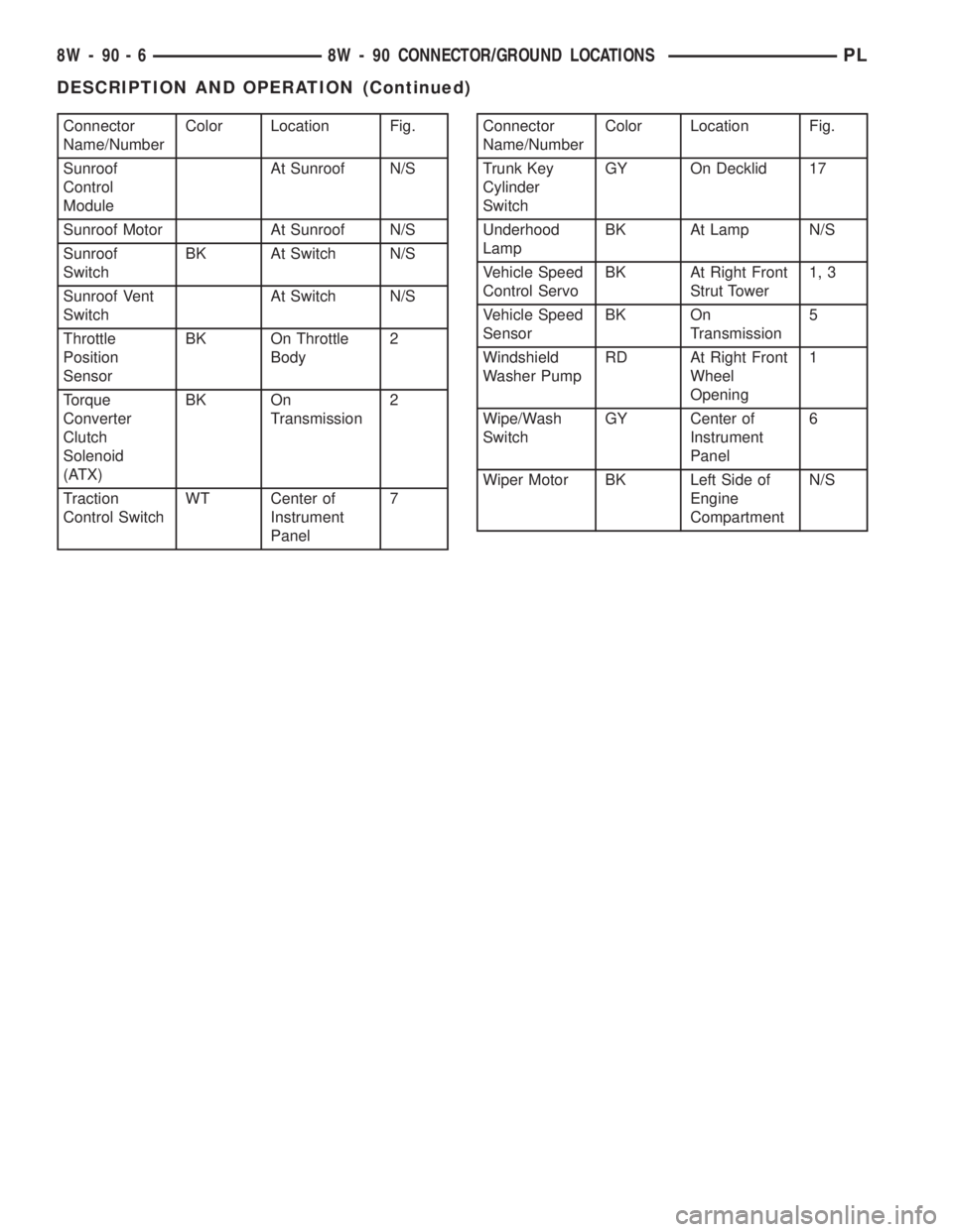
Connector
Name/NumberColor Location Fig.
Sunroof
Control
ModuleAt Sunroof N/S
Sunroof Motor At Sunroof N/S
Sunroof
SwitchBK At Switch N/S
Sunroof Vent
SwitchAt Switch N/S
Throttle
Position
SensorBK On Throttle
Body2
Torque
Converter
Clutch
Solenoid
(ATX)BK On
Transmission2
Traction
Control SwitchWT Center of
Instrument
Panel7Connector
Name/NumberColor Location Fig.
Trunk Key
Cylinder
SwitchGY On Decklid 17
Underhood
LampBK At Lamp N/S
Vehicle Speed
Control ServoBK At Right Front
Strut Tower1, 3
Vehicle Speed
SensorBK On
Transmission5
Windshield
Washer PumpRD At Right Front
Wheel
Opening1
Wipe/Wash
SwitchGY Center of
Instrument
Panel6
Wiper Motor BK Left Side of
Engine
CompartmentN/S
8W - 90 - 6 8W - 90 CONNECTOR/GROUND LOCATIONSPL
DESCRIPTION AND OPERATION (Continued)
Page 680 of 1285
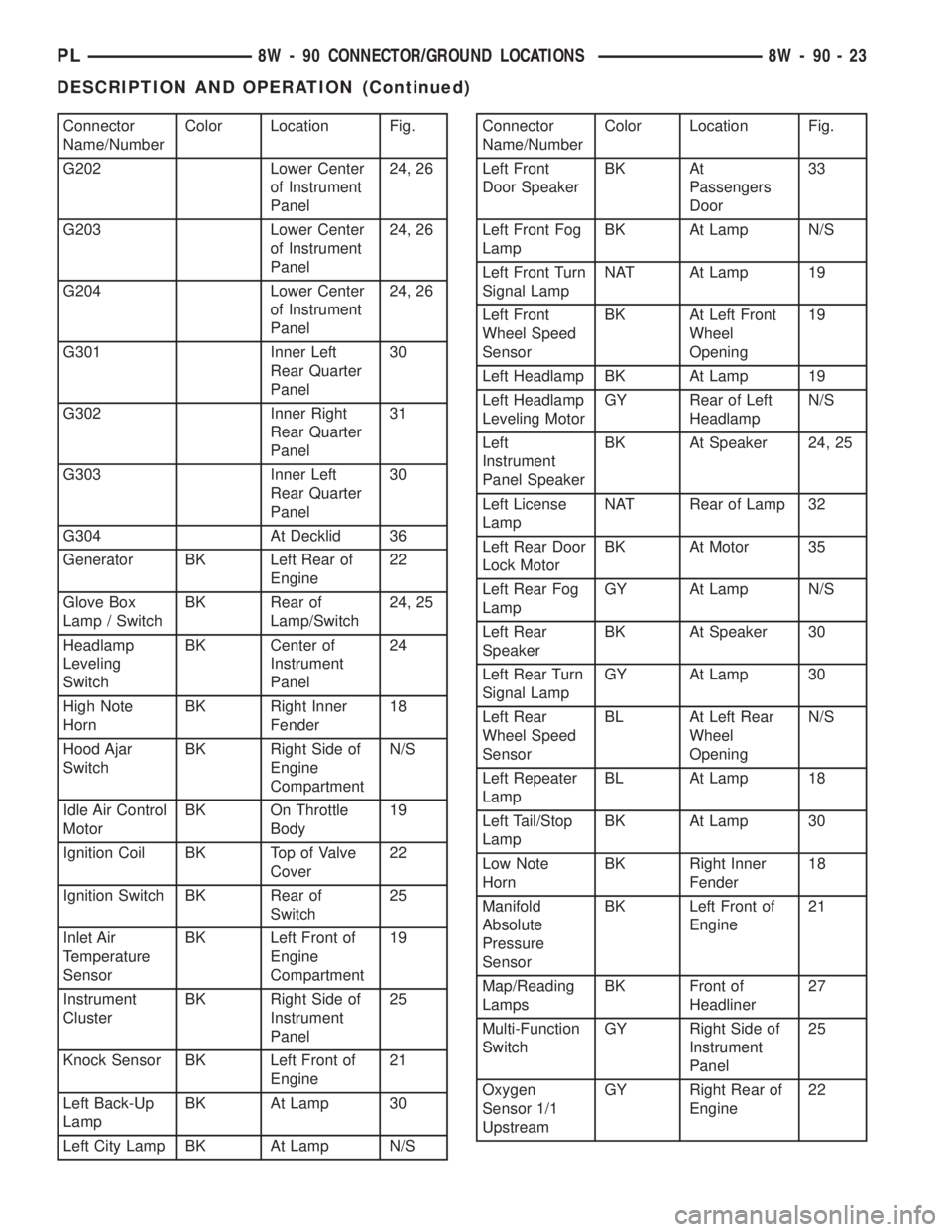
Connector
Name/NumberColor Location Fig.
G202 Lower Center
of Instrument
Panel24, 26
G203 Lower Center
of Instrument
Panel24, 26
G204 Lower Center
of Instrument
Panel24, 26
G301 Inner Left
Rear Quarter
Panel30
G302 Inner Right
Rear Quarter
Panel31
G303 Inner Left
Rear Quarter
Panel30
G304 At Decklid 36
Generator BK Left Rear of
Engine22
Glove Box
Lamp / SwitchBK Rear of
Lamp/Switch24, 25
Headlamp
Leveling
SwitchBK Center of
Instrument
Panel24
High Note
HornBK Right Inner
Fender18
Hood Ajar
SwitchBK Right Side of
Engine
CompartmentN/S
Idle Air Control
MotorBK On Throttle
Body19
Ignition Coil BK Top of Valve
Cover22
Ignition Switch BK Rear of
Switch25
Inlet Air
Temperature
SensorBK Left Front of
Engine
Compartment19
Instrument
ClusterBK Right Side of
Instrument
Panel25
Knock Sensor BK Left Front of
Engine21
Left Back-Up
LampBK At Lamp 30
Left City Lamp BK At Lamp N/SConnector
Name/NumberColor Location Fig.
Left Front
Door SpeakerBK At
Passengers
Door33
Left Front Fog
LampBK At Lamp N/S
Left Front Turn
Signal LampNAT At Lamp 19
Left Front
Wheel Speed
SensorBK At Left Front
Wheel
Opening19
Left Headlamp BK At Lamp 19
Left Headlamp
Leveling MotorGY Rear of Left
HeadlampN/S
Left
Instrument
Panel SpeakerBK At Speaker 24, 25
Left License
LampNAT Rear of Lamp 32
Left Rear Door
Lock MotorBK At Motor 35
Left Rear Fog
LampGY At Lamp N/S
Left Rear
SpeakerBK At Speaker 30
Left Rear Turn
Signal LampGY At Lamp 30
Left Rear
Wheel Speed
SensorBL At Left Rear
Wheel
OpeningN/S
Left Repeater
LampBL At Lamp 18
Left Tail/Stop
LampBK At Lamp 30
Low Note
HornBK Right Inner
Fender18
Manifold
Absolute
Pressure
SensorBK Left Front of
Engine21
Map/Reading
LampsBK Front of
Headliner27
Multi-Function
SwitchGY Right Side of
Instrument
Panel25
Oxygen
Sensor 1/1
UpstreamGY Right Rear of
Engine22
PL8W - 90 CONNECTOR/GROUND LOCATIONS 8W - 90 - 23
DESCRIPTION AND OPERATION (Continued)
Page 682 of 1285
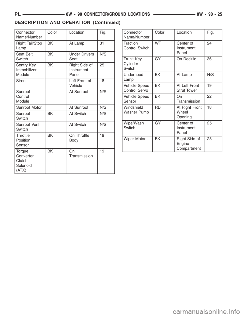
Connector
Name/NumberColor Location Fig.
Right Tail/Stop
LampBK At Lamp 31
Seat Belt
SwitchBK Under Drivers
SeatN/S
Sentry Key
Immobilizer
ModuleBK Right Side of
Instrument
Panel25
Siren Left Front of
Vehicle18
Sunroof
Control
ModuleAt Sunroof N/S
Sunroof Motor At Sunroof N/S
Sunroof
SwitchBK At Switch N/S
Sunroof Vent
SwitchAt Switch N/S
Throttle
Position
SensorBK On Throttle
Body19
Torque
Converter
Clutch
Solenoid
(ATX)BK On
Transmission19Connector
Name/NumberColor Location Fig.
Traction
Control SwitchWT Center of
Instrument
Panel24
Trunk Key
Cylinder
SwitchGY On Decklid 36
Underhood
LampBK At Lamp N/S
Vehicle Speed
Control ServoBK At Left Front
Strut Tower19
Vehicle Speed
SensorBK On
Transmission22
Windshield
Washer PumpRD At Right Front
Wheel
Opening18
Wipe/Wash
SwitchGY Center of
Instrument
Panel25
Wiper Motor BK Right Side of
Engine
Compartment23
PL8W - 90 CONNECTOR/GROUND LOCATIONS 8W - 90 - 25
DESCRIPTION AND OPERATION (Continued)
Page 997 of 1285
PARK/NEUTRAL STARTING AND BACK-UP
LAMP SWITCH
TEST
The park/neutral starting switch is the center ter-
minal of the three terminal switch. It provides
ground for the starter solenoid circuit through the
selector lever in PARK and NEUTRAL positions only.
(1) To test switch, remove wiring connector from
switch and test for continuity between center pin of
switch and transaxle case. Continuity should exist
only when transaxle is in PARK or NEUTRAL.
(2) Check gearshift cable adjustment before replac-
ing a switch that tests bad.
REMOVAL
(1) Unscrew switch from transaxle case allowing
fluid to drain into a container. Move selector lever to
PARK, then to NEUTRAL position, and inspect to see
the switch operating lever fingers are centered in
switch opening.
INSTALLATION
(1) Screw the switch with a new seal into tran-
saxle case and tighten to 33 N´m (24 ft. lbs.). Retest
switch with the test lamp.
(2) Add fluid to transaxle to bring up to proper
level.
(3) The back-up lamp switch circuit is through the
two outside terminals of the three terminal switch.
(4) To test switch, remove wiring connector from
switch and test for continuity between the two out-
side pins.
(5) Continuity should exist only with transaxle in
REVERSE position.
(6) No continuity should exist from either pin to
the case.
TRANSAXLE AND TORQUE CONVERTER
REMOVAL
(1) Raise hood.
(2) Disconnect both battery cables, remove battery
hold down clamp and bolt, and remove battery.
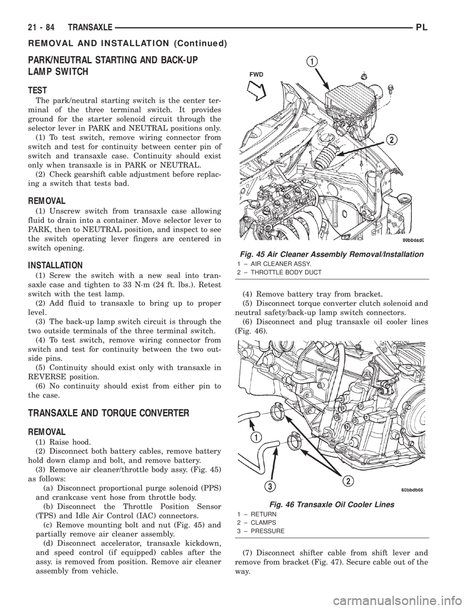
(3) Remove air cleaner/throttle body assy. (Fig. 45)
as follows:
(a) Disconnect proportional purge solenoid (PPS)
and crankcase vent hose from throttle body.
(b) Disconnect the Throttle Position Sensor
(TPS) and Idle Air Control (IAC) connectors.
(c) Remove mounting bolt and nut (Fig. 45) and
partially remove air cleaner assembly.
(d) Disconnect accelerator, transaxle kickdown,
and speed control (if equipped) cables after the
assy. is removed from position. Remove air cleaner
assembly from vehicle.(4) Remove battery tray from bracket.
(5) Disconnect torque converter clutch solenoid and
neutral safety/back-up lamp switch connectors.
(6) Disconnect and plug transaxle oil cooler lines
(Fig. 46).
(7) Disconnect shifter cable from shift lever and
remove from bracket (Fig. 47). Secure cable out of the
way.
Fig. 45 Air Cleaner Assembly Removal/Installation
1 ± AIR CLEANER ASSY.
2 ± THROTTLE BODY DUCT
Fig. 46 Transaxle Oil Cooler Lines
1 ± RETURN
2 ± CLAMPS
3 ± PRESSURE
21 - 84 TRANSAXLEPL
REMOVAL AND INSTALLATION (Continued)
Page 1122 of 1285
(4) Place protective covers over instrument panel
and hood.
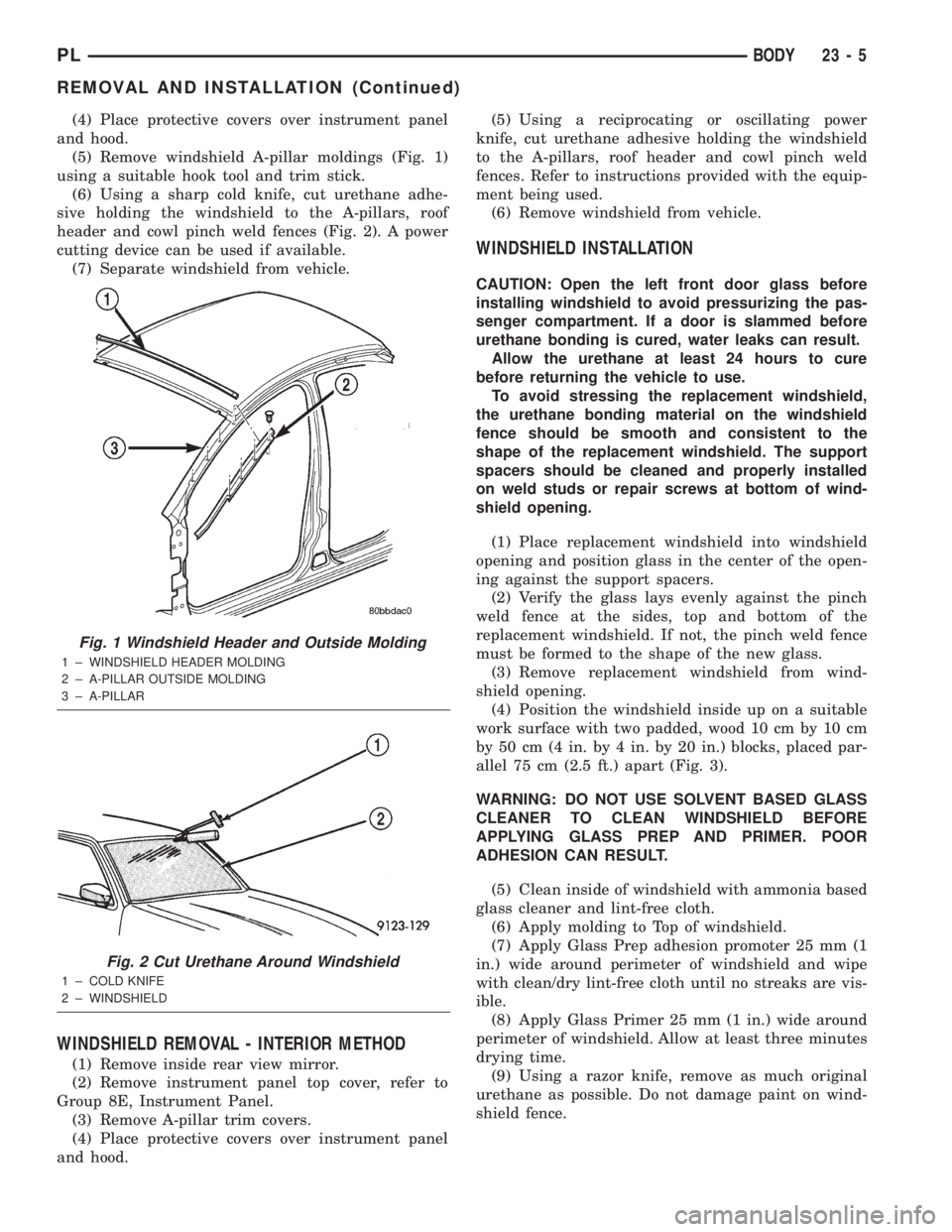
(5) Remove windshield A-pillar moldings (Fig. 1)
using a suitable hook tool and trim stick.
(6) Using a sharp cold knife, cut urethane adhe-
sive holding the windshield to the A-pillars, roof
header and cowl pinch weld fences (Fig. 2). A power
cutting device can be used if available.
(7) Separate windshield from vehicle.
WINDSHIELD REMOVAL - INTERIOR METHOD
(1) Remove inside rear view mirror.
(2) Remove instrument panel top cover, refer to
Group 8E, Instrument Panel.
(3) Remove A-pillar trim covers.
(4) Place protective covers over instrument panel
and hood.(5) Using a reciprocating or oscillating power
knife, cut urethane adhesive holding the windshield
to the A-pillars, roof header and cowl pinch weld
fences. Refer to instructions provided with the equip-
ment being used.
(6) Remove windshield from vehicle.
WINDSHIELD INSTALLATION
CAUTION: Open the left front door glass before
installing windshield to avoid pressurizing the pas-
senger compartment. If a door is slammed before
urethane bonding is cured, water leaks can result.
Allow the urethane at least 24 hours to cure
before returning the vehicle to use.
To avoid stressing the replacement windshield,
the urethane bonding material on the windshield
fence should be smooth and consistent to the
shape of the replacement windshield. The support
spacers should be cleaned and properly installed
on weld studs or repair screws at bottom of wind-
shield opening.
(1) Place replacement windshield into windshield
opening and position glass in the center of the open-
ing against the support spacers.
(2) Verify the glass lays evenly against the pinch
weld fence at the sides, top and bottom of the
replacement windshield. If not, the pinch weld fence
must be formed to the shape of the new glass.
(3) Remove replacement windshield from wind-
shield opening.
(4) Position the windshield inside up on a suitable
work surface with two padded, wood 10 cm by 10 cm
by 50 cm (4 in. by 4 in. by 20 in.) blocks, placed par-
allel 75 cm (2.5 ft.) apart (Fig. 3).
WARNING: DO NOT USE SOLVENT BASED GLASS
CLEANER TO CLEAN WINDSHIELD BEFORE
APPLYING GLASS PREP AND PRIMER. POOR
ADHESION CAN RESULT.
(5) Clean inside of windshield with ammonia based
glass cleaner and lint-free cloth.
(6) Apply molding to Top of windshield.
(7) Apply Glass Prep adhesion promoter 25 mm (1
in.) wide around perimeter of windshield and wipe
with clean/dry lint-free cloth until no streaks are vis-
ible.
(8) Apply Glass Primer 25 mm (1 in.) wide around
perimeter of windshield. Allow at least three minutes
drying time.
(9) Using a razor knife, remove as much original
urethane as possible. Do not damage paint on wind-
shield fence.
Fig. 1 Windshield Header and Outside Molding
1 ± WINDSHIELD HEADER MOLDING
2 ± A-PILLAR OUTSIDE MOLDING
3 ± A-PILLAR
Fig. 2 Cut Urethane Around Windshield
1 ± COLD KNIFE
2 ± WINDSHIELD
PLBODY 23 - 5
REMOVAL AND INSTALLATION (Continued)
Page 1129 of 1285
BODY COMPONENTS
TABLE OF CONTENTS
page page
DESCRIPTION AND OPERATION
GRILLE................................13
HOOD.................................13
FRONT DOOR...........................14
SPLASH SHIELD.........................16
DIAGNOSIS AND TESTING
WATER LEAKS..........................18
WIND NOISE............................19
SERVICE PROCEDURES
HEAT STAKING..........................19
PLASTIC BODY PANEL REPAIR..............19
REMOVAL AND INSTALLATION
GRILLE................................23
HOOD LATCH...........................24
HOOD LATCH STRIKER....................24
HOOD RELEASE CABLE...................25
HOOD.................................26
HOOD SILENCER........................26
HOOD HINGE...........................26
COWL COVER...........................27
FRONT WHEELHOUSE SPLASH SHIELD......28
FENDER...............................28
EXTERIOR BADGEING ATTACHED WITH
DOUBLE SIDED FOAM TAPE..............28
EXTERIOR BADGEING/TAPE STRIPES
ATTACHED WITH ADHESIVES.............28
FRONT/REAR DOOR WINDOW CRANK........29
FRONT DOOR TRIM......................30
FRONT DOOR WATER DAM................30
DOOR OUTER BELT WEATHERSTRIP.........30
FRONT/REAR DOOR INNER BELT
WEATHERSTRIP........................32
FRONT DOOR GLASS RUN WEATHERSTRIP . . . 32
FRONT DOOR OUTSIDE HANDLE............33
DOOR LOCK CYLINDER...................33
FRONT DOOR LATCH.....................33
FRONT DOOR LATCH STRIKER.............34
FRONT VERTICAL GUIDE BAR..............34
FRONT DOOR GLASS.....................36
FRONT DOOR CHECK STRAP..............36
FRONT DOOR...........................36
FRONT DOOR HINGE.....................38
FRONT/REAR DOOR APPLIQUE.............38
SIDE VIEW MIRROR......................39
SIDE VIEW MIRROR TRIM BEZEL............39
DOOR UPPER SECONDARY WEATHERSTRIP . . 39
SILL SECONDARY WEATHERSTRIP..........40
REAR DOOR TRIM.......................40REAR DOOR WATER DAM.................40
REAR DOOR OUTSIDE HANDLE.............40
REAR DOOR LATCH......................41
REAR DOOR LATCH STRIKER..............43
REAR DOOR GLASS......................43
REAR DOOR WINDOW REGULATOR.........43
REAR DOOR GLASS RUN WEATHERSTRIP....43
REAR DOOR CHECK STRAP................45
REAR DOOR............................45
REAR DOOR HINGE......................45
FUEL FILL DOOR.........................46
DECKLID LATCH.........................47
DECKLID...............................47
DECKLID LIFT SPRINGS...................47
DECKLID LOCK CYLINDER.................48
DECKLID LATCH STRIKER.................48
DECKLID OPENING WEATHERSTRIP.........49
TRUNK CARPET.........................49
DECKLID COVER.........................50
ROOF RAIL WEATHERSTRIP................50
ROOF RAIL WEATHERSTRIP RETAINER
CHANNEL.............................50
B-PILLAR WEATHERSTRIP CHANNEL.........51
A-PILLAR TRIM..........................51
DOOR SILL TRIM.........................51
SIDE COWL TRIM........................52
B-PILLAR TRIM..........................52
UPPER QUARTER TRIM...................53
LOWER QUARTER TRIM...................53
FLOOR CONSOLE........................54
FRONT SEAT BELT BUCKLE................54
FRONT SEAT BELT RETRACTOR............54
FRONT SHOULDER BELT ADJUSTER.........54
REAR SEAT BELT BUCKLE.................55
REAR SEAT BELT RETRACTOR.............55
CARPET...............................56
SUN VISOR.............................56
HEADLINER.............................57
INSIDE REAR VIEW MIRROR...............57
REAR SHELF TRIM PANEL.................57
BODY VENT.............................58
ADJUSTMENTS
FRONT DOOR LATCH ADJUSTMENT.........58
REAR DOOR LATCH ADJUSTMENT..........58
SPECIFICATIONS
BODY LUBRICATION......................59
SPECIAL TOOLS
BODY.................................59
23 - 12 BODYPL
Page 1140 of 1285
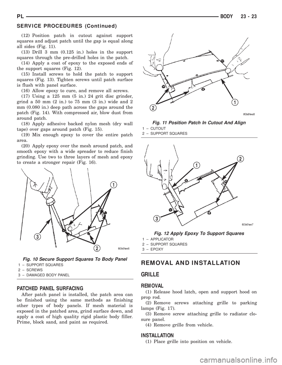
(12) Position patch in cutout against support
squares and adjust patch until the gap is equal along
all sides (Fig. 11).
(13) Drill 3 mm (0.125 in.) holes in the support
squares through the pre-drilled holes in the patch.
(14) Apply a coat of epoxy to the exposed ends of
the support squares (Fig. 12).
(15) Install screws to hold the patch to support
squares (Fig. 13). Tighten screws until patch surface
is flush with panel surface.
(16) Allow epoxy to cure, and remove all screws.
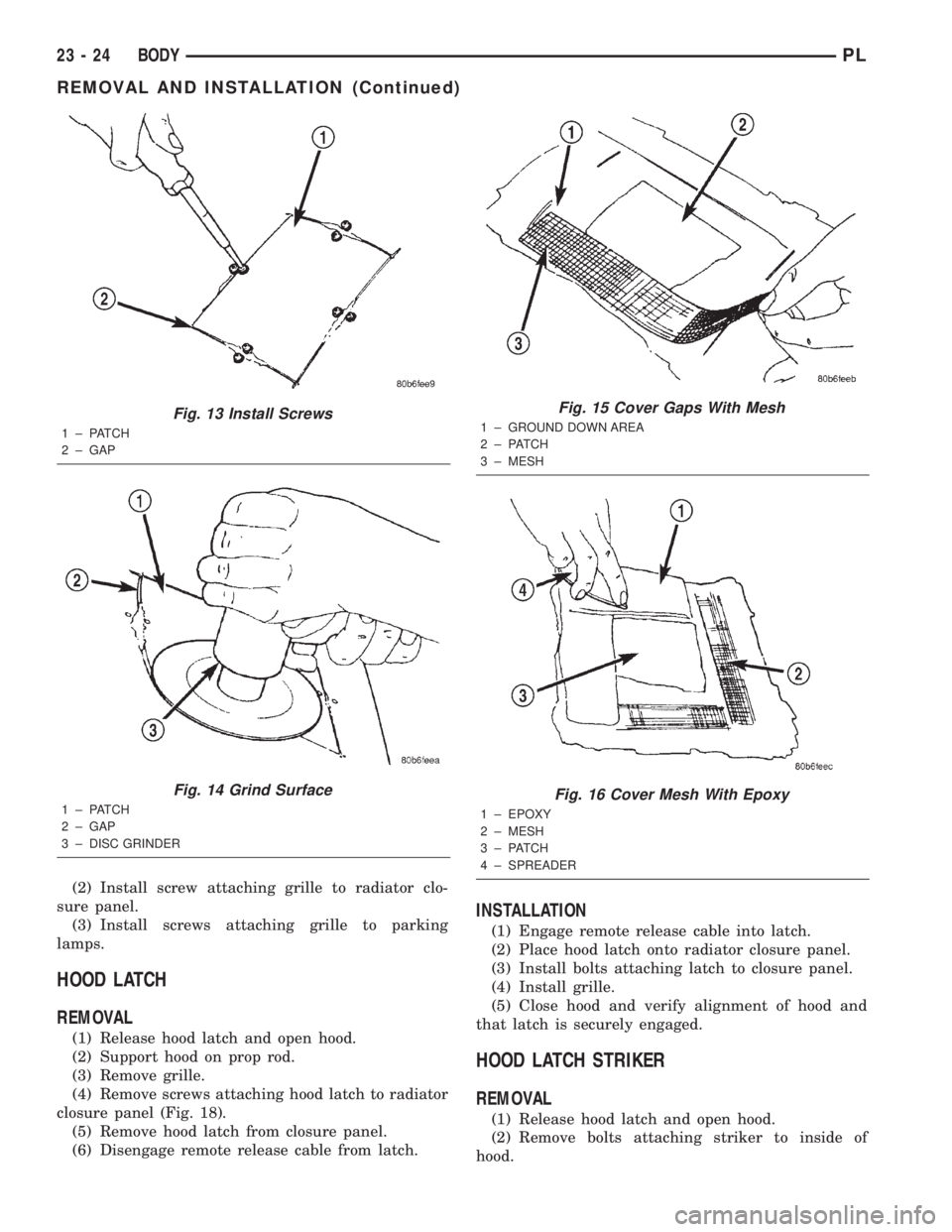
(17) Using a 125 mm (5 in.) 24 grit disc grinder,
grind a 50 mm (2 in.) to 75 mm (3 in.) wide and 2
mm (0.080 in.) deep path across the gaps around the
patch (Fig. 14). With compressed air, blow dust from
around patch.
(18) Apply adhesive backed nylon mesh (dry wall
tape) over gaps around patch (Fig. 15).
(19) Mix enough epoxy to cover the entire patch
area.
(20) Apply epoxy over the mesh around patch, and
smooth epoxy with a wide spreader to reduce finish
grinding. Use two to three layers of mesh and epoxy
to create a stronger repair (Fig. 16).
PATCHED PANEL SURFACING
After patch panel is installed, the patch area can
be finished using the same methods as finishing
other types of body panels. If mesh material is
exposed in the patched area, grind surface down, and
apply a coat of high quality rigid plastic body filler.
Prime, block sand, and paint as required.
REMOVAL AND INSTALLATION
GRILLE
REMOVAL
(1) Release hood latch, open and support hood on
prop rod.
(2) Remove screws attaching grille to parking
lamps (Fig. 17).
(3) Remove screw attaching grille to radiator clo-
sure panel.
(4) Remove grille from vehicle.
INSTALLATION
(1) Place grille into position on vehicle.
Fig. 10 Secure Support Squares To Body Panel
1 ± SUPPORT SQUARES
2 ± SCREWS
3 ± DAMAGED BODY PANEL
Fig. 11 Position Patch In Cutout And Align
1 ± CUTOUT
2 ± SUPPORT SQUARES
Fig. 12 Apply Epoxy To Support Squares
1 ± APPLICATOR
2 ± SUPPORT SQUARES
3 ± EPOXY
PLBODY 23 - 23
SERVICE PROCEDURES (Continued)
Page 1141 of 1285
(2) Install screw attaching grille to radiator clo-
sure panel.
(3) Install screws attaching grille to parking
lamps.
HOOD LATCH
REMOVAL
(1) Release hood latch and open hood.
(2) Support hood on prop rod.
(3) Remove grille.
(4) Remove screws attaching hood latch to radiator
closure panel (Fig. 18).
(5) Remove hood latch from closure panel.
(6) Disengage remote release cable from latch.
INSTALLATION
(1) Engage remote release cable into latch.
(2) Place hood latch onto radiator closure panel.
(3) Install bolts attaching latch to closure panel.
(4) Install grille.
(5) Close hood and verify alignment of hood and
that latch is securely engaged.
HOOD LATCH STRIKER
REMOVAL
(1) Release hood latch and open hood.
(2) Remove bolts attaching striker to inside of
hood.
Fig. 13 Install Screws
1 ± PATCH
2 ± GAP
Fig. 14 Grind Surface
1 ± PATCH
2 ± GAP
3 ± DISC GRINDER
Fig. 15 Cover Gaps With Mesh
1 ± GROUND DOWN AREA
2 ± PATCH
3 ± MESH
Fig. 16 Cover Mesh With Epoxy
1 ± EPOXY
2 ± MESH
3 ± PATCH
4 ± SPREADER
23 - 24 BODYPL
REMOVAL AND INSTALLATION (Continued)