Page 25 of 37
25
MFL CRUISE CONTROL DATA SIGNAL
The ME 7.2 control module provides the FGR cruise control function. Throttle activation is
provided by ME 7.2 automatic control of the EDK and monitoring of the throttle plate posi-
tion feedback potentiometer signals.
All of the familiar driver requested cruise control function requests are provided to the ME
7.2 control module via the MFL control module on a single FGR data signal wire.
BRAKE LIGHT SWITCH
The Electronic Brake Switch (Hall effect) provides brake pedal position status to the ME 7.2.
The control module monitors both the brake light and a separate brake light test switch cir-
cuits for plausibility.
When the brake pedal is pressed the brake light segment of the switch provides a ground
signal. Simultaneously, the brake light test switch (located in the same housing) provides a
high signal.
Page 26 of 37
26
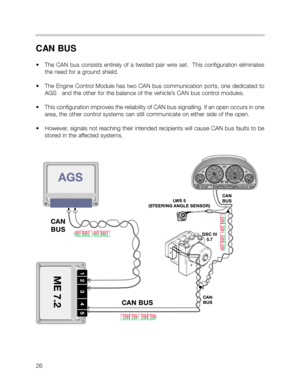
CAN BUS
• The CAN bus consists entirely of a twisted pair wire set. This configuration eliminates
the need for a ground shield.
• The Engine Control Module has two CAN bus communication ports, one dedicated to
AGS and the other for the balance of the vehicle’s CAN bus control modules.
• This configuration improves the reliability of CAN bus signalling. If an open occurs in one
area, the other control systems can still communicate on either side of the open.
• However, signals not reaching their intended recipients will cause CAN bus faults to be
stored in the affected systems.
Page 27 of 37
27
OUTPUT CONTROL FUNCTIONS
FUEL PUMP RELAY CONTROL
ME 7.2 controls the fuel pump relay as with previous systems with regard to engine speed
input for continual activation of the relay.
The ME 7.2 will switch off the fuel pump relay when an airbag is activated as an addition-
al safety function. The signal is passed from the MRS III control module to the ME 7.2 over
the CAN line
E BOX FAN CONTROL
The E Box fan is controlled by ME 7.2. The control module
contains an integral NTC temperature sensor for the pur-
pose of monitoring the E box temperature and activating the
fan.
When the temperature in the E-Box exceeds predetermined
values, ME 7.2 provides a switched ground for the E Box fan
to cool the E box located control modules.
With every engine start-up, ME 7.2 briefly activates the fan
ensuring continued fan motor operation for the service life of
the vehicle. This feature is intended to prevent fan motor
“lock up” from lack of use due to pitting or corrosion over
time.
Page 28 of 37

28
SECONDARY AIR INJECTION
Secondary air injections required to pre-heat the catalytic converters for OBD II compliance.
The system consists of the same components as previous systems with V8 specific loca-
tions.
The DME ME7.2 control unit controls the vacuum vent valve and the secondary air injec-
tion pump relay separately but simultaneously.
The secondary air pump operates at a start temperature of between 10°C and 40°C. It con-
tinues to operate for a max. of 2 minutes at idle speed.
ME 7.2 contributes an additional correction factor for secondary air “on” time with the addi-
tional input from the integral ambient barometric pressure sensor.
This sensor provides a base value to calculate the air mass being
injected into the exhaust system. This helps to “fine tune” the sec-
ondary air injection “on” time, optimizing the necessary air flow
into the exhaust system which reduces the time to catalytic con-
verter light-off.
VACUUM
VACUUM
VENT VALVENONPUMP/MOTOR
AIR PUMP SUPPLY HOSE
AIR DELIVERY TUBE WITH O RING
CONNECTIONS TO CYLINDER HEADS
VACUUM
CONTROL TO
NON RETURN
VA LV E
Page 29 of 37
29
AUXILIARY FAN CONTROL
The Auxiliary Fan motor incorporates an out-
put final stage that activates the fan motor at
variable speeds.
The auxiliary fan is controlled by ME 7.2. The
motor output stage receives power and
ground and activates the motor based on a
PWM signal (10 - 100 Hz) received from the
ME 7.2.
Similar to the aux fan in the E46 with MS 42.0
control, the fan is activated based on the fol-
lowing factors:
• Radiator outlet temperature sensor input exceeds a preset temperature.
• IHKA signalling via the K and CAN bus based on calculated refrigerant pressures.
• Vehicle speed
• Battery voltage level
When the over temperature light in the instrument cluster is on (120
OC) the fan is run in the
overrun function. This signal is provided to the DME via the CAN bus. When this occurs
the fan is run at a frequency of 10 Hz.
FAN MOTOR MODULE
POWER, GROUND & SIGNAL WIRES
Page 30 of 37
 CONTROL
• The throttle valve assembly of the M62 TU is an
electric throttle valve (EDK) controlled by an inte-
gral EML function of the ME 7.2.
•")
30
ELECTRIC THROTTLE VALVE (EDK) CONTROL
• The throttle valve assembly of the M62 TU is an
electric throttle valve (EDK) controlled by an inte-
gral EML function of the ME 7.2.
• The throttle plate is positioned by a gear reduction
DC motor drive.
• The motor is controlled by proportionately
switched high/low PWM signals at a basic fre-
quency of 2000 Hz.
• Engine idle speed control is a function of the EDK.
Therefore, the M62 TU does not require a separate
idle control valve.
HARNESS
CONNECTORMOTOR
REDUCTION
GEARS
POTENTIOMETER WIRES
THROTTLE
PLATE
EDK ADAPTATION
PROCEDURE:
When a replacement EDK
is installed the adaptation
values of the previous EDK
must be cleared from the
ME 7.2 control module.
1. From the Service
Function Menu of the
DIS/MoDiC, clear
adaptation values.
2. Switch the ignition OFF
for 10 seconds.
3. Switch the ignition ON
(KL 15). At approxi-
mately 30 seconds the
EDK is briefly activated
allowing the ME 7.2 to
“electrically learn” the
new component.
This procedure is also necessary after replacing an ME 7.2 control module. However, the
adaptation values do not require clearing since they have not yet been established.
Page 31 of 37
31
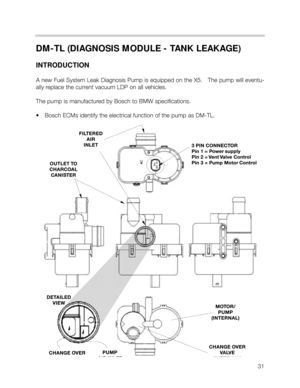
DM-TL (DIAGNOSIS MODULE - TANK LEAKAGE)
INTRODUCTION
A new Fuel System Leak Diagnosis Pump is equipped on the X5. The pump will eventu-
ally replace the current vacuum LDP on all vehicles.
The pump is manufactured by Bosch to BMW specifications.
• Bosch ECMs identify the electrical function of the pump as DM-TL.
Page 32 of 37
Functional Overview:
The DM-TL is located in the drivers side rear
wheel well in the X5.
1. In it’s inactive state, filtered fresh air enters the
evaporative system through the sprung open
valve of the DM-TL.
2. When the DME activates the DM-TL for leak
testing, it first activates only the pump motor.
This pumps air through a restricter orifice (1.0
or 0.5 mm) which causes the electric motor to
draw a specific amperage value. This value is
equivalent to the size of the restricter.
3. The solenoid valve is then energized which
seals the evap system and directs the pump
output to pressurize the evap system.
The evap system is detected as having a large leak if the amperage value is not realized, a
small leak if the same reference amperage is realized or no leak if the amperage value is
32
123


INTRODUCTION
A new Fuel System Leak Diagnosis Pump is equipped on the X5. The pump will eventu-
ally replace the current vacuum LDP on all vehicles.
The pu")
