Page 17 of 37
17
INTEGRAL ELECTRIC THROTTLE SYSTEM (EML)
FUNCTIONAL DESCRIPTION
When the accelerator pedal
is moved, the PWG pro-
vides a change in the mon-
itored signals. The ME 7.2
compares the input signal
to a programmed map and
appropriately activates the
EDK motor via proportional-
ly high/low switching cir-
cuits. The control module
self-checks it’s activation of
the EDK motor via the EDK
feedback potentiometers.
Requirements placed on the Electric Throttle System:
• Regulate the calculated intake air load based on PWG input signals and programmed
mapping.
• Control idle air when LL detected with regard to road speed as per previous systems.
• Monitor the driver’s input request for cruise control operation.
• Automatically position the EDK for accurate cruise control (FGR) operation.
• Perform all DSC III throttle control interventions.
• Monitor and carryout max engine and road speed cutout.
Page 18 of 37
 representing the driver’")
18
PWG SIGNAL MONITORING & PWG FAILSAFE OPERATION:
• As a redundant safety feature the PWG provides two separate signals from two integral
potentiometers (Pot 1 and Pot 2) representing the driver’s request for throttle activation.
• If the monitored PWG potentiometer signals are not plausible, ME 7.2 will only use the
lower of the two signals as the driver’s pedal request input providing failsafe operation.
Throttle response will be slower and maximum throttle position will be reduced.
• When in PWG failsafe operation, ME 7.2 sets the EDK throttle plate and injection time
to idle (LL) whenever the brake pedal is depressed.
• When the system is in PWG failsafe operation, the instrument cluster matrix display will
post “Engine Emergency Program” and PWG specific fault(s) will be stored in memory.
EDK FEEDBACK SIGNAL MONITORING & EDK FAILSAFE OPERATION:
• The EDK provides two separate signals from two integral potentiometers (Pot 1 and Pot
2) representing the exact position of the throttle plate.
• EDK Pot 1 provides the primary throttle plate position feedback. As a redundant safe-
ty feature, Pot 2 is continuously cross checked with Pot 1 for signal plausibility.
• If plausibility errors are detected between Pot 1 and Pot 2, ME 7.2 will calculate the
inducted engine air mass (from HFM signal) and only utilize the potentiometer signal that
closely matches the detected intake air mass.
- The ME 7.2 uses the air mass signalling as a “virtual potentiometer” (pot 3) for a
comparative source to provide failsafe operation.
- If ME 7.2 cannot calculate a plausible conclusion from the monitored pots (1 or 2
and virtual 3) the EDK motor is switched off and fuel injection cut out is activated
(no failsafe operation possible).
• The EDK is continuously monitored during all phases of engine operation. It is also
briefly activated when KL 15 is initially switched on as a “pre-flight check” to verify it’s
mechanical integrity (no binding, appropriate return spring tension, etc). This is accom-
plished by monitoring both the motor control amperage and the reaction speed of the
EDK feedback potentiometers. If faults are detected the EDK motor is switched off and
fuel injection cut off is activated (no failsafe operation possible). The engine does how-
ever continue to run extremely rough at idle speed.
• When a replacement EDK is installed, the ME 7.2 adapts to the new component
(required amperage draw for motor control, feedback pot tolerance differences, etc).
This occurs immediately after the next cycle of KL 15 for approximately 30 seconds.
During this period of adaptation, the maximum opening of the throttle plate is 25%.
Page 19 of 37

19
INPUT SIGNALS/COMPONENTS
CAMSHAFT POSITION SENSORS
Located on the upper timing case covers, the camshaft position sensors monitor the posi-
tion of the camshafts to establish start of ignition firing order, set up sequential fuel injection
triggering and for accurate camshaft advance-retard (VANOS) timing feedback.
Each intake camshaft’s advance-retard angles are adjusted simultaneously yet indepen-
dently. For this reason ME 7.2 requires a camshaft position sensor on each cy linder bank
for accurate feedback to monitor the VANOS controlled camshaft positioning.
The sensors are provided with operating power from the ECM main relay. The sensors pro-
duce a unique asymmetrical square-wave signal representative of the impulse wheel shape.
The sensors are new in the fact that they are “active” hall effect sensors. Active hall sen-
sors provide:
• low signal when a tooth of the camshaft impulse wheel is located in front of the sensor
• high signal when an air gap is present.
The active hall sensors supply a signal representative of camshaft position even before the
engine is running. The ME 7.2 determines an approximate location of the camshafts posi-
tions prior to engine start up optimizing cold start injection (reduced emissions.)
UNIQUE SIGNAL
AS SEEN IN
MEASUREMENT
SYSTEM
OSCILLOSCOPE
Page 20 of 37
20
HOT FILM AIR MASS SENSOR (HFM 5)
The M62 TU is equipped with a new Hot Film
Air Mass Sensor identified as HFM 5. It is a
combined air mass/intake air temperature
sensor. The separate intake air temperature
sensor is no longer used on the M62 TU.
The HFM 5 is provided with operating power
from the ECM main relay. Based on calcu-
lated intake air mass, the HFM 5 generates
a varying voltage between 0.5 and 4.5 volts
as an input signal to the ME 7.2
An additional improvement of the HFM 5 is that the hot
film element is not openly suspended in the center bore
of the sensor as with previous HFMs. It is shrouded by
a round fronted plastic labyrinth which isolates it from
intake air charge pulsations.
This feature allows the HFM to monitor and calculate the
intake air volume with more accuracy. This feature adds
further correction for calculating fuel injection “on” time
(ti) which reduces emissions further.
HFM 5 WITH
NEW CONNECTOR
HOT
SENSING
FILM
ROUNDED
LABYRINTH
Page 21 of 37
11
INTEGRATED AMBIENT BAROMETRIC PRESSURE SENSOR
The ME 7.2 Control Module contains an integral ambient barometric pressure sensor. The
sensor is part of the SKE and is not serviceable. The internal sensor is supplied with 5 volts.
In return it provides a linear voltage of approx. 2.4 to 4.5 volts representative of barometric
pressure (altitude).
The ME 7.2 monitors barometric pressure for the following reasons:
• The barometric pressure signal along with calculated air mass provides an additional
correction factor to further refine injection “on” time.
• Provides a base value to calculate the air mass being injected into the exhaust system
by the secondary air injection system. This correction factor alters the secondary air
injection “on” time, optimizing the necessary air flow into the exhaust system.
• Recognition of altitude
above the accepted cri-
teria postponing DM-TL
activation for evapora-
tive emission leak diag-
nosis.
21
Page 22 of 37

22
RADIATOR OUTLET TEMP SENSOR
First seen on the MS 42.0 control system, the ME
7.2 uses an additional water temperature sensor
located on the radiator outlet.
ME 7.2 requires this signal to monitor the water
temperature leaving the radiator for precise acti-
vation of the IHKA auxiliary fan.
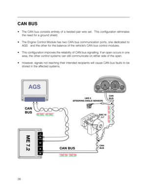
DSC III - ROAD SPEED SIGNAL
ME 7.2 receives the road speed signal directly
from the DSC III control module for maximum
vehicle speed management. The DSC control
module provides a processed output of the right
rear wheel speed sensor as a digital square wave
signal. The frequency of the signal is proportion-
al to the speed of the vehicle (48 pulses per one
revolution of the wheel).
The cruise control function (FGR) of the ME 7.2 also monitors vehicle speed from the redun-
dant vehicle speed CAN bus signal. The CAN bus speed signal is provided by the DSC III
control module and based on the combined average of both front wheel speed signals.
Additionally, ME 7.2 monitors all four wheel speed signals via CAN bus signalling to detect
abrupt fluctuations in vehicle speed signals for the purpose of detecting rough road sur-
faces. This is continuously monitored as part of the OBD II emission requirements provid-
ing a correction factor for misfire detection plausibility. Earlier systems only monitored the
right rear speed signal input from DSC.
Page 23 of 37

The drivers application of the accelerator pedal is monitored by a PWG sensor in the dri-
vers footwell as with previous non-bowden cable EML systems.
The PWG prov")
23
ACCELERATOR PEDAL SENSOR (PWG)
The driver's application of the accelerator pedal is monitored by a PWG sensor in the dri-
ver's footwell as with previous non-bowden cable EML systems.
The PWG provides two separate variable voltage signals to the ME 7.2 control module for
determining the request for operating the Electric Throttle Valve (EDK) as well as providing
a kickdown request with automatic transmission vehicles.
The ME 7.2 monitors the changing signal
ranges of both circuits as the pedal is pressed
from LL to VL.
• In vehicles equipped with an automatic transmission (A5S 440Z), the ME 7.2 recognizes
the max pedal value (4.5V) as a kickdown request and signals the AGS via CAN bus.
PWG SIGNAL MONITORING & PWG FAILSAFE OPERATION:
• If the monitored PWG potentiometer signals are not plausible, ME 7.2 will only use the
lower of the two signals as the driver’s pedal request input providing failsafe operation.
Throttle response will be slower and maximum throttle position will be reduced.
• When in PWG failsafe operation, ME 7.2 sets the EDK throttle plate and injection time
to idle (LL) whenever the brake pedal is depressed.
• When the system is in PWG failsafe operation, the instrument cluster matrix display will
post “Engine Emergency Program” and PWG specific fault(s) will be stored in memory.
Page 24 of 37

24
EDK THROTTLE POSITION FEEDBACK SIGNALS
The EDK throttle plate position is monitored by two integrated potentiometers. The poten-
tiometers provide DC voltage feedback signals as input to the ME 7.2 for throttle and idle
control functions.
Potentiometer signal 1 is the primary signal, Potentiometer sig-
nal 2 is used as a plausibility cross-check through the total
range of throttle plate movement.
EDK FEEDBACK
SIGNAL MONITORING & FAILSAFE OPERATION:
• If plausibility errors are detected between Pot 1 and Pot 2, ME 7.2 will calculate the
inducted engine air mass (from HFM signal) and only utilize the potentiometer signal that
closely matches the detected intake air mass.
- The ME 7.2 uses the air mass signalling as a “virtual potentiometer” (pot 3) for a
comparative source to provide failsafe operation.
- If ME 7.2 cannot calculate a plausible conclusion from the monitored pots (1 or 2
and virtual 3) the EDK motor is switched off and fuel injection cut out is activated
(no failsafe operation possible).
• The EDK is continuously monitored during all phases of engine operation. It is also
briefly activated when KL 15 is initially switched on as a “pre-flight check” to verify it’s
mechanical integrity (no binding, appropriate return spring tension) by monitoring the
motor control amperage and the reaction speed of the EDK feedback potentiometers.
If faults are detected the EDK motor is switched off and fuel injection cut off is activat-
ed (no failsafe operation possible). The engine does however continue to run extreme-
ly rough at idle speed.


FUNCTIONAL DESCRIPTION
When the accelerator pedal
is moved, the PWG pro-
vides a change in the mon-
itored signals. The ME 7.2
compares the inp")

The M62 TU is equipped with a new Hot Film
Air Mass Sensor identified as HFM 5. It is a
combined air mass/intake air temperature
sensor. The separate intake a")
