Page 145 of 189
145n
IndexDataTechnologyRepairsCar careControlsOverview
Lamps and bulbsSide turn signal indicator
*
5 watt bulb
1 Use finger pressure against the rear
end of the lens (arrow) to press it for-
ward for removal.
2 Apply gentle pressure to the bulb
while turning it to the left to remove.460de135
Front fog lamps HB4, 55 watt bulb
The bulb is pressurized. There-
fore, wear safety glasses and pro-
tective gloves. Failure to comply with
this precaution could lead to injury if the
bulb is accidentally damaged during re-
placement.<
1 Using a screwdriver, carefully loosen
the lamp.
2 Applying light pressure, turn the bulb
to the left. Remove and exchange the
bulb.460de132
Tail lamps Tail lamps (4): bulbs 21/4 watts
Remaining bulbs: 21 watts
1 Turn signal indicator yellow
2 Backup lamps white
3 Tail lamp red
4 Tail lamps/Brake lamps red460us046
Page 146 of 189
146n
Lamps and bulbsThe illustration shows the right-hand
luggage compartment opening.
Bulbs in the fender:
All of the bulbs are integrated in a cen-
tral bulb holder.
1 Release the bulb holder (arrow, par-
tial view) and remove.
2 Unplug the power supply receptacle.
Set the bulb holder aside (on the
luggage compartment floor, for ex-
ample).
3 Applying light pressure, turn the bulb
to the left. Remove and exchange the
bulb.
4 Plug in the power supply receptacle.
5 Position the bulb holder for reinstalla-
tion. Apply gentle pressure on the
button (arrow, partial view) until you
hear it engage.460de057
Bulbs in the luggage compartment lid:
1 Using a screwdriver, loosen the two
clips.460de131
2 Fold the trim panel down (arrow 1).
Disengage the bulb holder (arrow 2)
and remove it.
3 Applying light pressure, turn the bulb
to the left. Remove and exchange the
bulb.
4 Press the bulb holder into position
until you hear it engage.
5 Reinstall the trim with the two clips.462us033
Page 151 of 189

151n
IndexDataTechnologyRepairsCar careControlsOverview
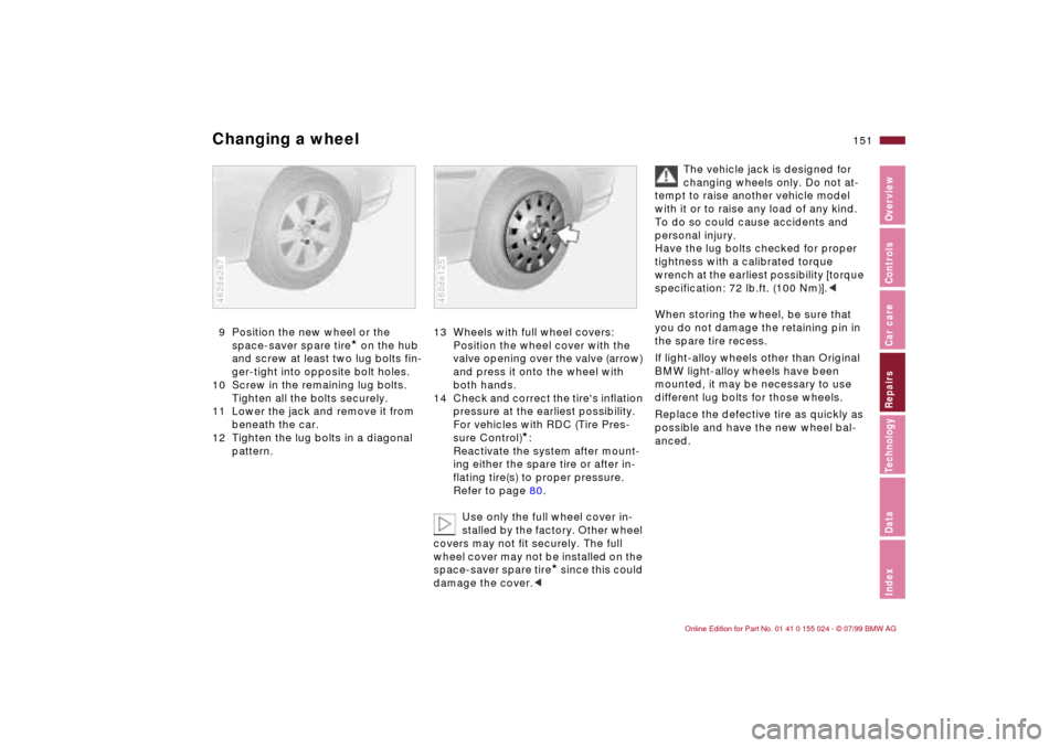
Changing a wheel9 Position the new wheel or the
space-saver spare tire
* on the hub
and screw at least two lug bolts fin-
ger-tight into opposite bolt holes.
10 Screw in the remaining lug bolts.
Tighten all the bolts securely.
11 Lower the jack and remove it from
beneath the car.
12 Tighten the lug bolts in a diagonal
pattern.
462de267
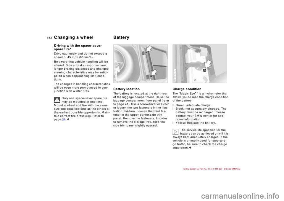
13 Wheels with full wheel covers:
Position the wheel cover with the
valve opening over the valve (arrow)
and press it onto the wheel with
both hands.
14 Check and correct the tire's inflation
pressure at the earliest possibility.
For vehicles with RDC (Tire Pres-
sure Control)
*:
Reactivate the system after mount-
ing either the spare tire or after in-
flating tire(s) to proper pressure.
Refer to page 80.
Use only the full wheel cover in-
stalled by the factory. Other wheel
covers may not fit securely. The full
wheel cover may not be installed on the
space-saver spare tire
* since this could
damage the cover.<
460de125
The vehicle jack is designed for
changing wheels only. Do not at-
tempt to raise another vehicle model
with it or to raise any load of any kind.
To do so could cause accidents and
personal injury.
Have the lug bolts checked for proper
tightness with a calibrated torque
wrench at the earliest possibility [torque
specification: 72 lb.ft. (100 Nm)].<
When storing the wheel, be sure that
you do not damage the retaining pin in
the spare tire recess.
If light-alloy wheels other than Original
BMW light-alloy wheels have been
mounted, it may be necessary to use
different lug bolts for those wheels.
Replace the defective tire as quickly as
possible and have the new wheel bal-
anced.
Page 152 of 189

152n
Changing a wheel Battery Driving with the space-saver
spare tire
*
Drive cautiously and do not exceed a
speed of 45 mph (80 km/h).
Be aware that vehicle handling will be
altered. Slower brake response time,
longer braking distances and changed
steering characteristics may be antici-
pated when approaching limit condi-
tions.
The changes in handling characteristics
will be even more pronounced in con-
junction with winter tires.
Only one space-saver spare tire
may be mounted at one time.
Mount a wheel and tire with the same
size and specifications as the others at
the earliest possible opportunity. Main-
tain correct tire pressures. Refer to
page 28.<
Battery locationThe battery is located at the right-rear
of the luggage compartment. Raise the
luggage compartment floor panel (refer
to page 41). Use a screwdriver or a coin
to loosen the two fasteners in the illus-
tration 1/4-turn. Loosen the third fas-
tener in the upper-center side trim
panel. Remove the fasteners. In order
to remove the storage tray, slide the
side trim panel slightly upward.460de176
Charge conditionThe "Magic Eye
*" is a hydrometer that
allows you to read the charge condition
of the battery:
>Green: adequate charge.
>Black: not adequately charged. The
battery must be recharged. Please
contact your BMW center for addi-
tional information.
>Yellow: Replace the battery.
The service life specified for the
battery can be achieved only if it is
always kept adequately charged. If the
vehicle is primarily used for stop-and-
go traffic, be sure to check the charge
state often.<
460de252
Page 161 of 189
Overview
Controls and features
Operation, care
and maintenance
Owner service procedures
Technical data
Index Advanced technology
161n
IndexDataTechnologyRepairsCar careControlsOverview
Adaptive Transmission Control
(ATC)162
Airbags163
Dynamic Stability Control
(DSC)163
Radio reception164
Safety belt tensioner164
Interior rearview mirror
with automatic dimming
feature165
Rain sensor166
Tire Pressure Control (RDC)167
Self-diagnostics168
Xenon lamps169
Technol-
Page 163 of 189

163n
IndexDataTechnologyRepairsCar careControlsOverview
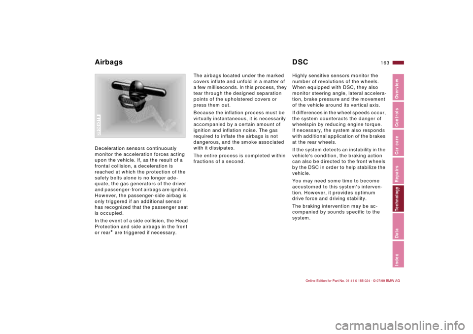
Deceleration sensors continuously
monitor the acceleration forces acting
upon the vehicle. If, as the result of a
frontal collision, a deceleration is
reached at which the protection of the
safety belts alone is no longer ade-
quate, the gas generators of the driver
and passenger-front airbags are ignited.
However, the passenger-side airbag is
only triggered if an additional sensor
has recognized that the passenger seat
is occupied.
In the event of a side collision, the Head
Protection and side airbags in the front
or rear
* are triggered if necessary.
390de319
The airbags located under the marked
covers inflate and unfold in a matter of
a few milliseconds. In this process, they
tear through the designed separation
points of the upholstered covers or
press them out.
Because the inflation process must be
virtually instantaneous, it is necessarily
accompanied by a certain amount of
ignition and inflation noise. The gas
required to inflate the airbags is not
dangerous, and the smoke associated
with it dissipates.
The entire process is completed within
fractions of a second.Highly sensitive sensors monitor the
number of revolutions of the wheels.
When equipped with DSC, they also
monitor steering angle, lateral accelera-
tion, brake pressure and the movement
of the vehicle around its vertical axis.
If differences in the wheel speeds occur,
the system counteracts the danger of
wheelspin by reducing engine torque.
If necessary, the system also responds
with additional application of the brakes
at the rear wheels.
If the system detects an instability in the
vehicle's condition, the braking action
can also be directed to the front wheels
by the DSC in order to help stabilize the
vehicle.
You may need some time to become
accustomed to this system's interven-
tion. However, it provides optimum
drive force and driving stability.
The braking intervention may be ac-
companied by sounds specific to the
system.
Airbags DSC
Page 164 of 189

164n
Radio reception Safety belt tensionerAM radio provides reception across a
considerable distance because the
broadcast signals not only travel along
the ground as surface waves, but they
are also reflected from the ionosphere
as atmospheric waves.
Frequency-modulation (FM) provides
substantially better sound quality than
AM. However, because FM transmis-
sions rely on line-of-sight broadcast
waves, their effective reception range is
limited. 360de084
The limitations inherent to radio recep-
tion in a moving vehicle have been min-
imized by a number of innovative sys-
tem designs:
The "Radio Data System" (RDS) makes
sure that, for broadcast stations send-
ing on several frequencies, the radio
automatically tunes to the frequency
with the best reception quality.
The Diversity Antenna system employs
several FM antennas integrated within
the rear window to provide three sepa-
rate sources for receiving broadcast
waves. An integral processor automati-
cally selects the antenna with the best
FM reception quality at any given time.
The selection of the antenna takes
place within milliseconds, and is there-
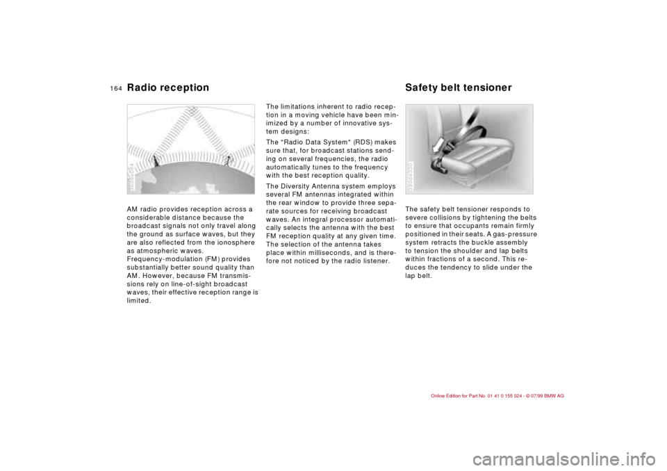
fore not noticed by the radio listener.The safety belt tensioner responds to
severe collisions by tightening the belts
to ensure that occupants remain firmly
positioned in their seats. A gas-pressure
system retracts the buckle assembly
to tension the shoulder and lap belts
within fractions of a second. This re-
duces the tendency to slide under the
lap belt.
390de330
Page 167 of 189
167n
IndexDataTechnologyRepairsCar careControlsOverview
Tire Pressure Control (RDC)
*
This system regularly checks tire pres-
sure and monitors all four tires even
while driving, so you don't have to.
Behind the valve stem in every wheel,
there is an electronic chip that is de-
signed for severe-duty applications and
long service life. It contains a pressure
sensor, a transmitter and a battery. The
pressure is measured in extremely short
time intervals and then transmitted by a
radio signal. If an irregularity is detected,
the transmission rate is increased. 460de169
Near every wheel is an antenna in the
body that receives the signal from the
wheel. A central electronics system
evaluates the quadruple signals and for-
wards any changes.
The RDC provides an important contri-
bution to driving safety.