Page 46 of 71

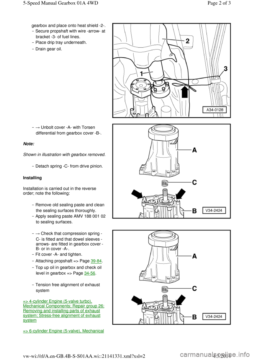
gearbox and place onto heat shield -2-. ‒ Secure propshaft with wire -arrow- at bracket -3- of fuel lines.
‒ Place drip tray underneath.
‒ Drain gear oil. ‒ → Unbolt cover -A- with Torsen
differential from gearbox cover -B-.
Note:
Shown in illustration with gearbox removed. ‒ Detach spring -C- from drive pinion.
Installing
Installation is carried out in the reverse
order; note the following:
‒ Remove old sealing paste and clean
the sealing surfaces thoroughly.
‒ Apply sealing paste AMV 188 001 02 to sealing surfaces. ‒ → Check that compression spring -
C- is fitted and that dowel sleeves -
arrows- are fitted in gearbox cover -
B- or in cover -A-.
‒ Fit cover -A- and tighten.
‒ Attaching propshaft => Page 39-84.
‒ Top up oil in gearbox and check oil
level in gearbox => Page 34-56.
‒ Tension free alignment of exhaust
system
=> 4-cylinder Engine (5-valve turbo), Mechanical Components; Repair group 26; Removing and installing parts of exhaust system; Stress-free alignment of exhaust system
=> 6-cylinder Engine (5-valve), Mechanical Page 2 of 35-Speed Manual Gearbox 01A 4WD4.3.2014vw-wi://rl/A.en-GB.4B-S-S01AA.wi::21141331.xml?xsl=2
Page 58 of 71
◆ V.A.G 1331 Torque wrench
◆ Sealant AMV 188 001 02 Notes:
◆ It is not necessary to remove the
differential to remove the above-
mentioned components => Page 34-74.
◆ Removal is only necessary when
adjustments have to be carried out
=> adjustment overview, Page 39-45.
Removing
‒ Place drip tray V.A.G 1306
underneath the gearbox.
‒ Drain gearbox oil using socket
attachment 3357.
‒ → Secure gearbox in assembly
stand VW 540. Page 2 of 115-Speed Manual Gearbox 01A 4WD4.3.2014vw-wi://rl/A.en-GB.4B-S-S01AA.wi::21141337.xml?xsl=2
Page 69 of 71
‒ → Check for a factory marking
(coloured dot) on the propshaft and
on the propshaft flange on the final drive at the rear. If not present, mark the position of the propshaft flange -
arrow A- relative to the rear final
drive -arrow B-.
‒ Remove the three upper securing
bolts from each constant velocity
joint on the propshaft. ‒ → Attach the assembly device 3139
with spacers 3139/3 and tighten the
plastic nuts.
Note:
Never fit assembly appliance onto balance plates.
‒ Remove the three remaining
securing bolts from the constant
velocity joints at the front and rear. ‒ → Remove the securing nuts Page 2 of 45-Speed Manual Gearbox 01A 4WD4.3.2014vw-wi://rl/A.en-GB.4B-S-S01AA.wi::21141363.xml?xsl=2
Page:
< prev 1-8 9-16 17-24