Page 17 of 166
13.5-15.5 ohms ( )
1) Engine at room temperature; with the engine at normal operating temperature the resistance increases by approx. 4-6
ohms.
Pa
ge 17 of 166 Motronic Multi
port Fuel In
jection
(MFI
) and i
gnition s
ystem
11/23/2002 htt
p://127.0.0.1:8080/audi/servlet/Dis
play?action=Goto&t
yp
e=re
pair&id=AUDI.B5.FU03.24.1
Page 18 of 166

24-14
Fuel injection system, servicing
Servicing ignition system page 28
-1
Notes:
Fuel hoses in the engine compartment must be
secured with spring-type clamps. Screw-type
clamps or equivalent must not be used.
The Engine Control Module (ECM) has On
Board Diagnostic (OBD) capability, and is
equipped with Diagnostic Trouble Code (DTC)
memory. Before repairing or adjusting any
components or systems, first check DTC
memory. Also check all vacuum connections for
leaks ("false air").
For proper operation of electrical and electronic
components, a Battery Positive Voltage (B+)
supply of at least 11.5 volts is required.
Do not use any gasket sealers or other
automotive chemical compounds that contain
silicone. Traces of silicone drawn into the
engine pass unburned into the exhaust and can
damage the oxygen sensors.
Do not use any electrical contact sprays or
equivalent near oxygen sensor connections.
Pa
ge 18 of 166 Motronic Multi
port Fuel In
jection
(MFI
) and i
gnition s
ystem
11/23/2002 htt
p://127.0.0.1:8080/audi/servlet/Dis
play?action=Goto&t
yp
e=re
pair&id=AUDI.B5.FU03.24.1
Page 19 of 166
Proper oxygen sensor function requires
reference to outside air via the cable. If any
contact spray reaches the oxygen sensor, it can
cause damage or improper function.
During some tests, malfunctions are recognized
by the ECM and stored in DTC memory. For
this reason, always check DTC memory (
page 01
-16
) after all tests and repairs, and
erase DTC memory as necessary.
Pa
ge 19 of 166 Motronic Multi
port Fuel In
jection
(MFI
) and i
gnition s
ystem
11/23/2002 htt
p://127.0.0.1:8080/audi/servlet/Dis
play?action=Goto&t
yp
e=re
pair&id=AUDI.B5.FU03.24.1
Page 20 of 166
24-15
Safety precautions page 24
-9
Rules of cleanliness page 24
-12
Technical data page 24
-13
Pa
ge 20 of 166 Motronic Multi
port Fuel In
jection
(MFI
) and i
gnition s
ystem
11/23/2002 htt
p://127.0.0.1:8080/audi/servlet/Dis
play?action=Goto&t
yp
e=re
pair&id=AUDI.B5.FU03.24.1
Page 21 of 166
24-16
Idle speed, checking
Notes:
Idle speed, ignition timing and CO-content
cannot be adjusted.
Idle speed is maintained by the Throttle valve
control module.
CO-content is maintained and adjusted by
Oxygen Sensor (O2S) control. Malfunctions in
O2S control are recognized by On Board
Diagnostic (OBD) and stored in DTC memory.
Required special tools and test equipment
VAG1551 or VAG1552 Scan Tool (ST) with
VAG1551/3 adapter cable
Pa
ge 21 of 166 Motronic Multi
port Fuel In
jection
(MFI
) and i
gnition s
ystem
11/23/2002 htt
p://127.0.0.1:8080/audi/servlet/Dis
play?action=Goto&t
yp
e=re
pair&id=AUDI.B5.FU03.24.1
Page 22 of 166
24-17
Test conditions
Fuses for engine electronics OK
No malfunctions stored in DTC memory
page 01
-16
Engine Coolant Temperature (ECT) at least
80 C (176 F)
All electrical consumers switched off
(radiator coolant fan must not run during
test)
A/C switched off
Exhaust system free of leaks
Automatic transmission selector lever in "P"
or "N" position
Throttle valve in Closed Throttle Position
(CTP); for Accelerator Pedal (AP) cable
adjustment Repair Manual, Fuel Supply
System, Repair Group 20
Pa
ge 22 of 166 Motronic Multi
port Fuel In
jection
(MFI
) and i
gnition s
ystem
11/23/2002 htt
p://127.0.0.1:8080/audi/servlet/Dis
play?action=Goto&t
yp
e=re
pair&id=AUDI.B5.FU03.24.1
Page 23 of 166

24-18
Checking
- Connect VAG1551 or VAG1552 scan tool and
press buttons -0- and -1- to insert "Engine
Electronics" address word 01 (with engine
running at idle) page 01
-8 .
Rapid data transfer
HELP
Select function XX
Indicated on display
- Press buttons -0- and -4- to select "Basic Setting" function 04, and
press -Q- button to confirm input.
System in Basic Settin
g
HELP
Input displa
y group number XXX
Indicated on display
- Press buttons -0-, -0- and -1- to input display group number 1 (001),
and press -Q- button to confirm input.
System in Basic Setting 1 1 2 3 4
Indicated on display (1-4 = display fields)
Note:
After selecting function 04, the ECM initiates the following:
EVAP canister purge regulator valve is closedA/C compressor is switched of
f
- Briefly raise engine speed (acceleration burst) and let engine run at idle
for another 2 minutes.
Pa
ge 23 of 166 Motronic Multi
port Fuel In
jection
(MFI
) and i
gnition s
ystem
11/23/2002 htt
p://127.0.0.1:8080/audi/servlet/Dis
play?action=Goto&t
yp
e=re
pair&id=AUDI.B5.FU03.24.1
Page 24 of 166
24-19
- Compare display with specified values (display
fields 1-4):
Display fields
1 2 3 4
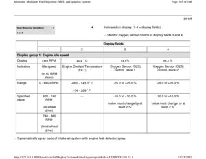
Display group 1: Engine idle speed
Display xxxx RPM
xx.x C
xx.x% xx.x %
Indicates Idle speed
(in 40 RPM steps) Engine Coolant
Temperature (ECT) Oxygen Sensor
(O2S) control, Bank
1 Oxygen Sensor
(O2S) control, Bank
2
Range 0 - 6800 RPM
-48.0 - 143.2 C
(-54 - 289 F)
-25.0 to +25.0 % -25.0 to +25.0 %
Specified
value 620 - 740 RPM
(all-wheel drive) 80.0 - 105.0 C
(176 - 221 F) -10.0 to +10.0 %
value must change by
at least 2 % -10.0 to +10.0 %
value must change by
at least 2 %
740 - 860 RPM
(front-wheel drive)
If not as specified Evaluation of
display group 1 page 24
-21
--- If not as specified:
- Check HO2S and O2S control before TWC
page 24
-22
Pa
ge 24 of 166 Motronic Multi
port Fuel In
jection
(MFI
) and i
gnition s
ystem
11/23/2002 htt
p://127.0.0.1:8080/audi/servlet/Dis
play?action=Goto&t
yp
e=re
pair&id=AUDI.B5.FU03.24.1