Page 17 of 96
01-371
Printed output from VAG1551
Scan Tool (ST) Possible cause
Corrective action
DTC
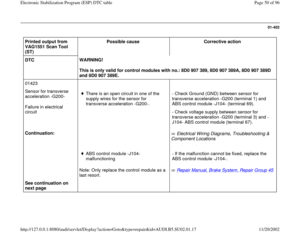
00302
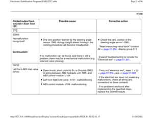
ABS solenoid valve relay -J106-
Voltage supply too low for ABS solenoid valve
relay -J106- (terminal 30).
- Carry out "Electrical test", step
22 page 01
-323
.
Continuation:
ABS solenoid valve relay -J106- or ABS
hydraulic unit -N55- malfunctioning.
Pa
ge 17 of 96 Electronic Stabilization Pro
gram
(ESP
) DTC table
11/20/2002 htt
p://127.0.0.1:8080/audi/servlet/Dis
play?action=Goto&t
yp
e=re
pair&id=AUDI.B5.SU02.01.17
Page 18 of 96
01-372
Printed output from
VAG1551 Scan Tool (ST) Possible cause
Corrective action
DTC
00526
Brake light switch -F-
Open circuit
Left brake light -M9- or right brake light -
M10- malfunctioning. Open circuit in wiring between brake lights
and the ABS control module -J104-. Electrical Wiring Diagrams,
Troubleshooting & Component Locations - Check the wiring. Carry out "Electrical
test", step 26 page 01
-323
.
- Replace bulbs.
See continuation on next
page
ABS control module -J104- malfunctioning
Repair Manual, Brake System, Repair
Group 45
- If the malfunction cannot be fixed,
replace the ABS control module -J104-.
Pa
ge 18 of 96 Electronic Stabilization Pro
gram
(ESP
) DTC table
11/20/2002 htt
p://127.0.0.1:8080/audi/servlet/Dis
play?action=Goto&t
yp
e=re
pair&id=AUDI.B5.SU02.01.17
Page 19 of 96
01-373
Printed output from
VAG1551 Scan Tool
(ST) Possible cause
Corrective action
DTC
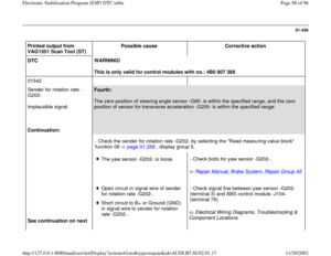
00526
Continuation:
Brake light switch -F-
Implausible signal
The brake light switch is not adjusted
correctly.
Note: The brake light switch must be
adjusted exactly. - Check brake light switch, "Read measuring
value block", display group 2 page 01
-256
Open circuit/short circuit to B+ or Ground
(GND) in wiring between brake light switch -
F- and the ABS control module -J104-. - Check wiring between brake light switch -F-
and the ABS control module -J104-. Carry out
"Electrical test", step 26 page 01
-323
.
See continuation on
next page
Brake light switch malfunctioning.
Repair Manual, Brake System, Repair
Group 46
- If the malfunction cannot be fixed. replace
the brake light switch.
Pa
ge 19 of 96 Electronic Stabilization Pro
gram
(ESP
) DTC table
11/20/2002 htt
p://127.0.0.1:8080/audi/servlet/Dis
play?action=Goto&t
yp
e=re
pair&id=AUDI.B5.SU02.01.17
Page 20 of 96
01-374
Printed output from VAG1551
Scan Tool (ST) Possible cause
Corrective action
DTC
00526
Brake light switch -F-
Implausible signal
Continuation:
ABS control module -J104-
malfunctioning
Repair Manual, Brake System, Repair Group 45
- If the malfunction cannot be fixed, replace the
ABS control module -J104-.
Master brake cylinder
malfunctioning.
Repair Manual, Suspension, Wheels, Steering,
Repair Group 47
- Check the master brake cylinder, and replace if
necessary.
Brake booster malfunctioning
Repair Manual, Suspension, Wheels, Steering,
Repair Group 47
- Check the brake booster, and replace if
necessary.
Pa
ge 20 of 96 Electronic Stabilization Pro
gram
(ESP
) DTC table
11/20/2002 htt
p://127.0.0.1:8080/audi/servlet/Dis
play?action=Goto&t
yp
e=re
pair&id=AUDI.B5.SU02.01.17
Page 21 of 96
 Possible cause
Corrective action
DTC
00532
Voltage supply
See continuation on next page")
01-375
DTC table; DTCs from 00532 to 01421
Printed output from VAG1551 Scan Tool
(ST) Possible cause
Corrective action
DTC
00532
Voltage supply
See continuation on next page
This malfunction affects the voltage supply
of the control module.
This DTC is only stored, if it occurs the first
time the vehicle exceeds 6 km/h.
As soon as the supply voltage is again
within the valid voltage range, the system
is switched back on and the warning lights
turn off.
Open circuit or resistance too high
between voltage supply of terminal 15
and ABS control module -J104-
(terminal 1). Open circuit or resistance too high in
the Ground (GND) supply to ABS
control module -J104- (terminals 28
and 29). Voltage jumps in vehicle system. Electrical Wiring Diagrams,
Troubleshooting & Component
Locations
Electrical Wiring Diagrams,
Troubleshooting & Component
Locations
Repair Manual, Electrical
Equipment, Repair Group 27, Battery
- "Read measuring value block"
function 08 page 01
-256
,
display group 6.
- Carry out "Electrical test",
step 21 page 01
-323
- Check Generator (GEN) and
Voltage Regulator (VR). - Check battery
Pa
ge 21 of 96 Electronic Stabilization Pro
gram
(ESP
) DTC table
11/20/2002 htt
p://127.0.0.1:8080/audi/servlet/Dis
play?action=Goto&t
yp
e=re
pair&id=AUDI.B5.SU02.01.17
Page 22 of 96
 Possible cause
Corrective action
DTC
00532
Continuation:
Voltage supply
Signal too small
This malfunction affects t")
01-376
Printed output from VAG1551 Scan Tool
(ST) Possible cause
Corrective action
DTC
00532
Continuation:
Voltage supply
Signal too small
This malfunction affects the voltage supply
of the control module.
This DTC is only stored, if it occurs the first
time the vehicle exceeds 6 km/h.
As soon as the supply voltage is again
within the valid voltage range, the system
is switched back on and the warning lights
turn off.
Open circuit or resistance too high
between voltage supply of terminal 15
and ABS control module -J104-
(terminal 1). Open circuit or resistance too high in
the Ground (GND) supply to ABS
control module -J104- (terminals 28
and 29). Voltage jumps in vehicle system. Electrical Wiring Diagrams,
Troubleshooting & Component
Locations
Electrical Wiring Diagrams,
Troubleshooting & Component
Locations
Repair Manual, Electrical
Equipment, Repair Group 27, Battery
- "Read measuring value block"
function 08 page 01
-256
,
display group 6.
- Carry out "Electrical test",
step 21 page 01
-323
- Check Generator (GEN) and
Voltage Regulator (VR). - Check battery
Pa
ge 22 of 96 Electronic Stabilization Pro
gram
(ESP
) DTC table
11/20/2002 htt
p://127.0.0.1:8080/audi/servlet/Dis
play?action=Goto&t
yp
e=re
pair&id=AUDI.B5.SU02.01.17
Page 23 of 96
01-377
Printed output from
VAG1551 Scan Tool (ST) Possible cause
Corrective action
DTC
00597
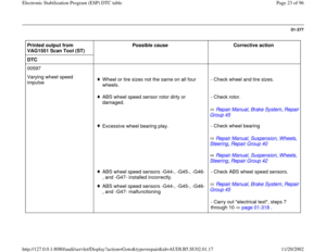
Varying wheel speed
impulse
Wheel or tire sizes not the same on all four
wheels. - Check wheel and tire sizes.
ABS wheel speed sensor rotor dirty or
damaged.
Repair Manual, Brake System, Repair
Group 45
- Check rotor.
Excessive wheel bearing play.
Repair Manual, Suspension, Wheels,
Steering, Repair Group 40
Repair Manual, Suspension, Wheels,
Steering, Repair Group 42
- Check wheel bearing
ABS wheel speed sensors -G44-, -G45-, -G46-
, and -G47- installed incorrectly.
ABS wheel speed sensors -G44-, -G45-, -G46-
, and -G47- malfunctioning Repair Manual, Brake System, Repair
Group 45
- Check ABS wheel speed sensors.
- Carry out "electrical test", steps 7
through 10 page 01
-318
.
Pa
ge 23 of 96 Electronic Stabilization Pro
gram
(ESP
) DTC table
11/20/2002 htt
p://127.0.0.1:8080/audi/servlet/Dis
play?action=Goto&t
yp
e=re
pair&id=AUDI.B5.SU02.01.17
Page 24 of 96
01-378
Printed output from
VAG1551 Scan Tool
(ST) Possible cause
Corrective action
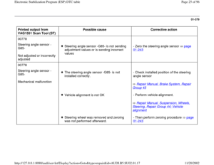
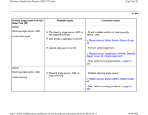
00778
Steering angle sensor -
G85-
no communication
Open circuit or loose contact in data-BUS
wires between steering angle sensor -G85-
and ABS control module (w/EDL) -J104- - Check fuses, wires and harness
connectors as well as voltage supply to the
control module: test step no. 13 page
01
-323
Check specified values of:
Steering angle sensor -G85-- Read measuring value block, function 08
page 01
-256
, display group number 004
Steering angle sensor -G85- malfunctioning
Repair Manual, Brake System, Repair
Group 45
- Replace steering angle sensor.
- Code the ABS control module (w/EDL) -
J104- page 01
-234
- Then perform zeroing procedure page 01
-243
Pa
ge 24 of 96 Electronic Stabilization Pro
gram
(ESP
) DTC table
11/20/2002 htt
p://127.0.0.1:8080/audi/servlet/Dis
play?action=Goto&t
yp
e=re
pair&id=AUDI.B5.SU02.01.17


 Possible cause
Corrective action
DTC
00302
ABS solenoid valve relay -J106-
Voltage supply too low for ABS solenoid valve")
 Possible cause
Corrective action
DTC
00526
Brake light switch -F-
Open circuit
Left brake light -M9- or right brake light -")
 Possible cause
Corrective action
DTC
00526
Continuation:
Brake light switch -F-
Implausible signal
The b")
 Possible cause
Corrective action
DTC
00526
Brake light switch -F-
Implausible signal
Continuation:
ABS control module")
 Possible cause
Corrective action
DTC
00597
Varying wheel speed
impulse
Wheel or tire sizes not the same on all four
wheels")
 Possible cause
Corrective action
00778
Steering angle sensor -
G85-
no communication
Open circuit or loose contact in data-BUS
wir")