Page 17 of 36
24-140
Explanation of 4-digit display
Explanation when display field is = 0
x
x
x
x
Display group 55
0 A/C compressor off (0 = A/C compressor off; 1 = A/C compressor on)
0 Shift lever in P or N (0 = Shift lever in P or N; 1 = Shift lever in 2/3/4/R/D)
0 Idle air control boost (0 = no idle air control boost, for all-wheel drive vehicles; 1 = idle air control boost, for
front-wheel drive vehicles)
0 always "0"
Note:
The increased idle speed (raised rpm) on vehicles with front-wheel drive is attained if there is power supplied (B+, 15er) to
terminal 10 of the engine control module.
Pa
ge 17 of 36 Throttle valve control module, checkin
g
11/23/2002 htt
p://127.0.0.1:8080/audi/servlet/Dis
play?action=Goto&t
yp
e=re
pair&id=AUDI.B5.FU03.24.2
Page 18 of 36
24-141
Continuation
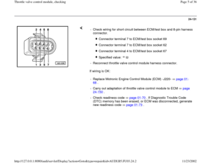
- Switch ignition off.
- Connect VAG1598/22 test box to ECM harness
connector page 01
-67
.
- Switch ignition on.
- With throttle valve in closed throttle position,
connect multimeter US1119 (Fluke 83 or
equivalent), and check resistance between
ECM/test box sockets 59 and 66.
Specified value: 3-200 If resistance is NOT OK:
- Disconnect 8-pin harness connector from throttle
valve control module -J338-.
- Check wiring for open circuit between ECM/test box and 8-pin throttle
valve control module harness connector.
Connector terminal 1 to ECM/test box socket 66
Connector terminal 2 to ECM/test box socket 59
Connector terminal 7 to ECM/test box socket 67
Pa
ge 18 of 36 Throttle valve control module, checkin
g
11/23/2002 htt
p://127.0.0.1:8080/audi/servlet/Dis
play?action=Goto&t
yp
e=re
pair&id=AUDI.B5.FU03.24.2
Page 19 of 36
Connector terminal 8 to ECM/test box socket 74
Specified value: max. 1.5
Pa
ge 19 of 36 Throttle valve control module, checkin
g
11/23/2002 htt
p://127.0.0.1:8080/audi/servlet/Dis
play?action=Goto&t
yp
e=re
pair&id=AUDI.B5.FU03.24.2
Page 20 of 36
24-142
If wiring is OK: - Check wiring of 8-pin connector for short circuit between wires,
according to wiring diagram.
Connector terminal 1 to ECM/test box socket 59
Connector terminal 1 to ECM/test box socket 74
Connector terminal 1 to ECM/test box socket 67
Connector terminal 2 to ECM/test box socket 67
Connector terminal 2 to ECM/test box socket 74
Connector terminal 7 to ECM/test box socket 74
Specified value:
- Carry out adaptation of throttle valve control module to ECM page
24
-150
.
- Check readiness code page 01
-70
. If Diagnostic Trouble Code
(DTC) memory has been erased, or ECM was disconnected, generate
new readiness code page 01
-73
.
Pa
ge 20 of 36 Throttle valve control module, checkin
g
11/23/2002 htt
p://127.0.0.1:8080/audi/servlet/Dis
play?action=Goto&t
yp
e=re
pair&id=AUDI.B5.FU03.24.2
Page 21 of 36
24-143
Throttle Position (TP) sensor, checking
Note:
The Throttle Position (TP) sensor -G69- is
located inside the throttle valve control module -
J338-.
Test conditions
Throttle valve in closed throttle position; if
necessary adjust accelerator pedal cable
Repair Manual, Fuel Supply System, Repair
Group 20
Cruise control adjustment OK
Power supply for throttle valve control
module OK; checking page 24
-130
Checking
- Connect VAG1551 or VAG1552 scan tool and
press buttons -0- and -1- to insert "Engine
Electronics" address word 01 (with ignition
switched; engine not running) page 01
-8 .
Pa
ge 21 of 36 Throttle valve control module, checkin
g
11/23/2002 htt
p://127.0.0.1:8080/audi/servlet/Dis
play?action=Goto&t
yp
e=re
pair&id=AUDI.B5.FU03.24.2
Page 22 of 36
Rapid data transfer
HELP
Select function XX
Indicated on display
- Press buttons -0- and -8- to select "Read Measuring Value Block"
function 08, and press -Q- button to confirm input.
Read Measurin
g Value Block
HELP
Input display group number XXX
Indicated on display
Pa
ge 22 of 36 Throttle valve control module, checkin
g
11/23/2002 htt
p://127.0.0.1:8080/audi/servlet/Dis
play?action=Goto&t
yp
e=re
pair&id=AUDI.B5.FU03.24.2
Page 23 of 36
24-144
- Press buttons -0-, -0- and -3- to input display
group number 3 (003), and press -Q- button to
confirm input. Read Measuring Value Block 3 1 2 3 4
Indicated on display (1-4 = display fields)
- Compare display with specified values for throttle angle, (display field
3):
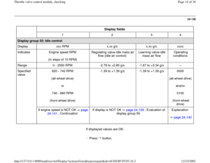
Display fields
1 2 3 4
Display group 3: Load measurement
Display xxx RPM xx.x g/s
xxx
xx.x BTDC
Indicates Engine speed
(in 40 RPM
steps) Mass air
flow Throttle angle Ignition timing
Range 0 - 6800 RPM ---
0 - 90
0.0 - 50.0
BTDC
Specified
value 0 RPM ---
0 - 5
0.0
--- --- If not as specified page 24
-146
, Evaluation of
display group 3
---
-
Open throttle valve slowly while monitoring degree ( ) value in display field 3. Value must increase uniformly over the entire range.
Pa
ge 23 of 36 Throttle valve control module, checkin
g
11/23/2002 htt
p://127.0.0.1:8080/audi/servlet/Dis
play?action=Goto&t
yp
e=re
pair&id=AUDI.B5.FU03.24.2
Page 24 of 36
-
Press button.
Pa
ge 24 of 36 Throttle valve control module, checkin
g
11/23/2002 htt
p://127.0.0.1:8080/audi/servlet/Dis
play?action=Goto&t
yp
e=re
pair&id=AUDI.B5.FU03.24.2


")


 sensor, checking
Note:
The Throttle Position (TP) sensor -G69- is
located inside the throttle valve control module -
J338-.
Test conditions")

, and press -Q- button to
confirm input. Read Measuring Value Block 3 1 2 3 4
Indicated on display (1-4 = d")
