Page 1396 of 4592
A07555
Battery
EFI
AM2
123
3 1J
B2A
2J Instrument Panel J/B
B
1B 1W
37
1 5
IG Switch
1
B±W
B±RST RelayEFI Relay
5
6
2 3
1 11 410
4
5 4
5
A 2B STARTER
(M/T)
B±G
II23
B±W
II211
Starter
Park/Neutral
Position Switch
Clutch Start
Switch
5 7
B±R Engine Room J/B No.2
2C
2F IGN
FL Block1
2D1
BMAIN
B±O (*3) W±B
GR (*2)
10B
C
1
CIR
OPN
Relay
L±B
IGG±R
W±B
14 2L
E7FCECM
E01
1
S1S2
Engine Room R/B
No.1
2
J40
J/C
G±RL±B
5 93
Fuel
Pump
L±B
R
EB B±R
GR
W±R
B±W
B±WB±O (*3)(A/T)
BL
J/CB±R
J8
2K
J7
B
1 1 1
B 1K
1K
1K
8 7
6
EB1 4
J29
J/C J11
J/CF6 1 W±R
MAIN
FL4
5 2K
2
B±R (*4)
*1: w/ Immobiliser(*1)
MREL
E107 B±W
B
B
B±WII4
6
F41
GR (*2)
*2: TMC Made
*3: TMMK Made A
(*1)
(*1)
GR (*2)
B±O (*3)(M/T)
*4: w/o Immobiliser
EB1 B±R
B±R (*1)
B±R (*4)
IK17
55
7
ID1
7 W±B
W±B
DI±184
± DIAGNOSTICSENGINE (5S±FE)
419 Author�: Date�:
WIRING DIAGRAM
Page 1397 of 4592
± DIAGNOSTICSENGINE (5S±FE)
DI±185
420 Author�: Date�:
INSPECTION PROCEDURE
TOYOTA hand±held tester:
1 Connect TOYOTA hand±held tester, and check operation of fuel pump
(See page DI±3).
OK Proceed to next circuit inspection shown on
problem symptoms table (See page DI±28).
NG
2 Check for ECM power source circuit (See page DI±179).
NG Repair or replace.
OK
3 Check circuit opening relay (Marking: CIR OPN) (See page SF±41).
NG Replace circuit opening relay.
OK
Page 1398 of 4592
A03029A03450
FC (+) ON
w/o Immobiliser
w/ Immobiliser
FC (+)
DI±186
± DIAGNOSTICSENGINE (5S±FE)
421 Author�: Date�:
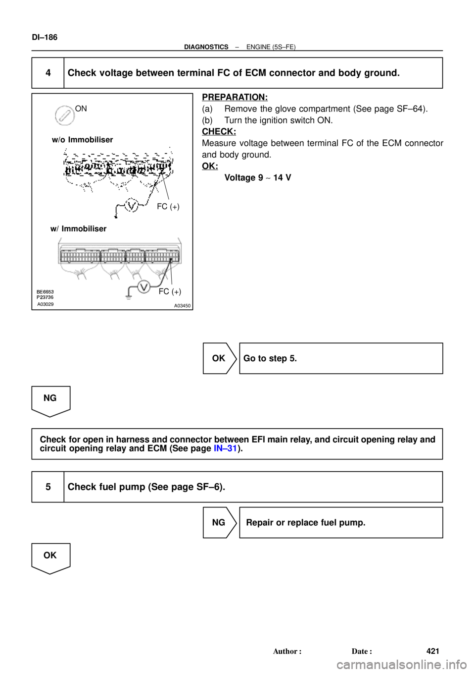
4 Check voltage between terminal FC of ECM connector and body ground.
PREPARATION:
(a) Remove the glove compartment (See page SF±64).
(b) Turn the ignition switch ON.
CHECK:
Measure voltage between terminal FC of the ECM connector
and body ground.
OK:
Voltage 9 ~ 14 V
OK Go to step 5.
NG
Check for open in harness and connector between EFI main relay, and circuit opening relay and
circuit opening relay and ECM (See page IN±31).
5 Check fuel pump (See page SF±6).
NG Repair or replace fuel pump.
OK
Page 1399 of 4592
A03030A03451
ON
FC
OFFON
Fuel Inlet Hose
FC
OFF
ON w/o Immobiliser
w/ Immobiliser
± DIAGNOSTICSENGINE (5S±FE)
DI±187
422 Author�: Date�:
6 Check for open in harness and connector between circuit opening relay (Mark-
ing: CIR OPN) and fuel pump, and fuel pump and body ground
(See page IN±31).
NG Repair or replace harness or connector.
OK
Check and replace ECM (See page IN±31).
OBD II scan tool (excluding TOYOTA hand±held tester):
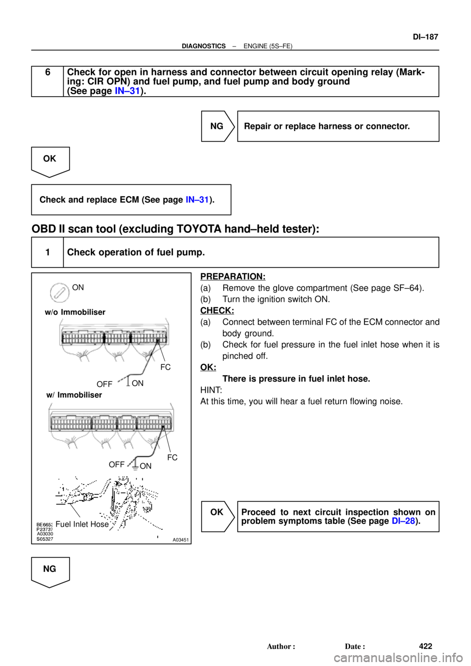
1 Check operation of fuel pump.
PREPARATION:
(a) Remove the glove compartment (See page SF±64).
(b) Turn the ignition switch ON.
CHECK:
(a) Connect between terminal FC of the ECM connector and
body ground.
(b) Check for fuel pressure in the fuel inlet hose when it is
pinched off.
OK:
There is pressure in fuel inlet hose.
HINT:
At this time, you will hear a fuel return flowing noise.
OK Proceed to next circuit inspection shown on
problem symptoms table (See page DI±28).
NG
Page 1400 of 4592
DI±188
± DIAGNOSTICSENGINE (5S±FE)
423 Author�: Date�:
2 Check for ECM power source circuit (See page DI±179).
NG Repair or replace.
OK
3 Check circuit opening relay (Marking: CIR OPN) (See page SF±41).
NG Replace circuit opening relay.
OK
4 Check voltage between terminal FC of ECM connector and body ground
(See page DI±183, step 4).
OK Go to step 5.
NG
Check for open in harness and connector between EFI main relay and circuit opening relay, and
circuit opening relay and ECM (See page IN±31).
5 Check fuel pump (See page SF±6).
NG Repair or replace fuel pump.
OK
Page 1401 of 4592
± DIAGNOSTICSENGINE (5S±FE)
DI±189
424 Author�: Date�:
6 Check for open in harness and connector between circuit opening relay (Mark-
ing: CIR OPN) and fuel pump, and fuel pump and body ground
(See page IN±31).
NG Repair or replace harness or connector.
OK
Check and replace ECM (See page IN±31).
Page 1417 of 4592
P20186
± DIAGNOSTICSENGINE (1MZ±FE)
DI±205
440 Author�: Date�:
7 Check fuel pressure.
PREPARATION:
(a) Be sure that enough fuel is in the tank.
(b) Connect the TOYOTA hand±held tester to the DLC3.
(c) Turn the ignition switch ON and push the TOYOTA hand±
held tester main switch ON.
(d) Use ACTIVE TEST mode to operate the fuel pump.
(e) If you have no TOYOTA hand±held tester, connect the
positive (+) and negative (±) leads from the battery to the
fuel pump connector (See page SF±6).
CHECK:
Check that the pulsation damper screw rises up when the fuel
pump operates.
NG Proceed to page SF±6 and continue to
troubleshoot.
OK
Page 1421 of 4592

DI±209
444 Author�: Date�:
(b) TOYOTA Enhanced Signals.
TOYOTA hand±held tester displayMeasurement ItemNormal Condition*
MISFIRE RPMEngine RPM for first misfire rangeM")
± DIAGNOSTICSENGINE (1MZ±FE)
DI±209
444 Author�: Date�:
(b) TOYOTA Enhanced Signals.
TOYOTA hand±held tester displayMeasurement ItemNormal Condition*
MISFIRE RPMEngine RPM for first misfire rangeMisfire 0: 0 rpm
MISFIRE LOADEngine load for first misfire rangeMisfire 0: 0 g/r
INJECTORFuel injection time for cylinder No.1Idling: 1.6 ~ 2.9 ms
IAC DUTY RATIOIntake Air Control Valve Duty Ratio
Opening ratio rotary solenoid type IAC valveIdling: 27 ~ 47 %
STARTER SIGStarter SignalCranking: ON
CTP SIGClosed Throttle Position SignalThrottle Fully Closed: ON
A/C SIGA/C Switch SignalA/C ON: ON
PNP SWPark/Neutral Position Switch SignalP or N position: ON
ELCTRCL LOAD SIGElectrical Load SignalDefogger switch ON: ON
STOP LIGHT SWStop Light Switch SignalStop light switch ON: ON
PS OIL PRESS SWPower Steering Oil Pressure Switch SignalTurn steering wheel: ON
FC IDLFuel Cut Idle: Fuel cut when throttle valve fully
closed, during decelerationFuel cut operating: ON
FC TAUFuel Cut TAU: Fuel cut during very light loadFuel cut operating: ON
CYL#1 ~ CYL#6Abnormal revolution variation for each cylinder0%
IGNITIONTotal number of ignition for every 1,000 revolu-
tions0 ~ 3,000
EGRT GASEGR Gas Temperature Sensor Value
EGR not operating:
Temperature between intake air temp. and
engine coolant temp.
INTAKE CTRL VSVIntake Air Control Valve VSV SignalVSV operating: ON
EGR SYSTEMEGR system operating conditionIdling: OFF
A/C CUT SIGA/C Cut SignalA/C S/W OFF: ON
FUEL PUMPFuel Pump SignalIdling: ON
EVAP (PURGE) VSVEVAP VSV SignalVSV operating: Above 30%
VAPOR PRESS VSVVapor Pressure VSV SignalVSV operating: ON (TANK)
*: If no conditions are specifically stated for ºldlingº, it means the shift lever is at N or P position, the A/C switch
is OFF and all accessory switches are OFF.

B±G
II23
B±W
II211
Starter
Park/Neutral")