Page 26 of 349

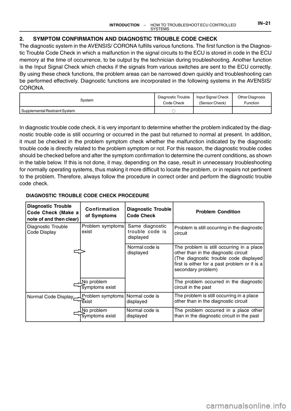
DIAGNOSTIC TROUBLE CODE CHECK PROCEDURE
Diagnostic Trouble
Code Check (Make a
note of and then clear)Confirmation
of SymptomsDiagnostic Trouble
Code CheckProblem Condition
Diagnostic Trouble
Code DisplayProblem symptoms
existSame diagnostic
trouble code is
displayedProblem is still occurring in the diagnostic
circuit
Normal code is
displayedThe problem is still occurring in a place
other than in the diagnostic circuit
(The diagnostic trouble code displayed
first is either for a past problem or it is a
secondary problem)
No problem
symptoms existThe problem occurred in the diagnostic
circuit in the past
Normal Code DisplayProblem symptoms
existNormal code is
displayedThe problem is still occurring in a place
other than in the diagnostic circuit
No problem
symptoms existNormal code is
displayedThe problem occurred in a place other
than in the diagnostic circuit in the past
– INTRODUCTIONHOW TO TROUBLESHOOT ECU CONTROLLED
SYSTEMSIN–21
2. SYMPTOM CONFIRMATION AND DIAGNOSTIC TROUBLE CODE CHECK
The diagnostic system in the AVENSIS/ CORONA fulfills various functions. The first function is the Diagnos-
tic Trouble Code Check in which a malfunction in the signal circuits to the ECU is stored in code in the ECU
memory at the time of occurrence, to be output by the technician during troubleshooting. Another function
is the Input Signal Check which checks if the signals from various switches are sent to the ECU correctly.
By using these check functions, the problem areas can be narrowed down quickly and troubleshooting can
be performed effectively. Diagnostic functions are incorporated in the following systems in the AVENSIS/
CORONA.
SystemDiagnostic Trouble
Code CheckInput Signal Check
(Sensor Check)Other Diagnosis
Function
Supplemental Restraint System�
In diagnostic trouble code check, it is very important to determine whether the problem indicated by the diag-
nostic trouble code is still occurring or occurred in the past but returned to normal at present. In addition,
it must be checked in the problem symptom check whether the malfunction indicated by the diagnostic
trouble code is directly related to the problem symptom or not. For this reason, the diagnostic trouble codes
should be checked before and after the symptom confirmation to determine the current conditions, as shown
in the table below. If this is not done, it may, depending on the case, result in unnecessary troubleshooting
for normally operating systems, thus making it more difficult to locate the problem, or in repairs not pertinent
to the problem. Therefore, always follow the procedure in correct order and perform the diagnostic trouble
code check.
Page 220 of 349

RS0IK–01
H03384
H11628
H03386
H03387
H03388
RS–2
– SUPPLEMENTAL RESTRAINT SYSTEMSRS AIRBAG
OPERATION
1. SIDE AIRBAG ASSEMBLY
The inflater and bag of the SRS side airbag are stored in the
side airbag assembly and cannot be disassembled. The inflater
contains a squib, igniter charge and gas generant, etc., and in-
flates the bag when instructed by the side airbag sensor assem-
bly.
2. CURTAIN SHIELD AIRBAG ASSEMBLY
The inflater and bag of the SRS curtain shield airbag are stored
in the curtain shield airbag assembly and cannot be disas-
sembled. The inflater contains a squib, igniter charge and gas
generant, etc., and inflates the bag when instructed by the side
airbag sensor assembly.
3. SRS WARNING LIGHT
The SRS warning light is located on the combination meter. It
goes on to alert the driver of trouble in the system when a mal-
function is detected in the airbag sensor assembly. In normal
operation conditions when the ignition switch is turned to the
ACC or ON position, the light goes on for about 6 seconds and
then goes off.
4. AIRBAG SENSOR ASSEMBLY
The airbag sensor assembly is mounted on the floor inside the
lower center finish panel. The airbag sensor assembly consists
of an airbag sensor, safing sensor, diagnosis circuit ignition
control and drive circuit, etc. It receives signals from the airbag
sensor, front airbag sensor, side airbag sensor and judges
whether the SRS must be activated or not.
5. SIDE AND CURTAIN SHIELD AIRBAG SENSOR AS-
SEMBLY
The side and curtain shield airbag sensor assembly is mounted
in the LH and RH center pillars. The side airbag sensor assem-
bly consists of a side airbag, sensor, safing sensor and diagno-
sis circuit, etc. It sends signals to the airbag sensor assembly
to judges whether the SRS side airbag must be activated or not.
Page 266 of 349

No.
AGround (Power)
Tacho Pick–UP Sensor
EFI ECU (3S–FE, 2C–TE Engine)
EGR (2C–T Engine)
Vehicle Speed Sensor
EFI ECU
Water Temperature Sender Gauge (2C–T Engine)
Ground (Engine)
Ground
Outside Temperature Sender Gauge
Ground (Fuel)
Fuel Sender Gauge
Ground (Power)
Ground (Speed)
Turn Signal Switch (Right)
Other Parts
Oil Level Warning Switch
O/D OFF Switch
ECT ECU (Gasoline Engine)
Fuel Filter Warning Switch (Diesel Engine)
Glow Plug Timer (Diesel Engine)
EFI ECU (Gasoline Engine)
ECT Pattern Select Switch
ABS ECU
Rear Fog Light Switch 1
3
5
6
7
8
9
10
11
12
14
15
17
18
19
21
22
23
24
25
26Wire Harness Side
1
2
3
4
5
6
7
9
11
13
14
15
16
17
18
19
20
22
24
26Turn Signal Switch (Left)
H–LP Fuse
Front Fog Light Switch
Alternator L Terminal
Brake Fluid Level Warning Switch
Parking Brake Switch
ECU+B Fuse
Taillight Relay
GAUGE Fuse
Ground (Signal)
DOOR Fuse
EFI ECU (Gasoline Engine)
EGR ECU (Diesel Engine)
Headlight Dimmer Switch
Low Oil Pressure Warning Switch
IGN Fuse
Door Courtesy Switch
Airbag ECU
Taillight Relay
GAUGE Fuse
Ground (Signal)
DOOR Fuse
B
– BODY ELECTRICALCOMBINATION METER
BE–5