Page 205 of 349

Z15498
Oil
reservoir
PS Vane
Pump
SST Closed PS Gear
Z15499
Oil
reservoir
PS Vane
Pump
SST Open Lock Position
PS Gear
Z15500
Oil
reservoir
PS Vane
Pump PS Gear
SST Open Lock Position
– STEERINGPOWER STEERING FLUID
SR–5
(f) With the engine idling, close the valve of the SST and ob-
serve the reading on the SST.
Minimum fluid pressure:
4A–FE and 7A–FE engines8,238 kPa (84 kgf/cm2, 1,195 psi)
3S–FE engine9,022 kPa (92 kgf/cm2, 1,309 psi)
2C–T, 2C–TE and 1CD–FTV engines8,826 kPa (90 kgf/cm2, 1,280 psi)
NOTICE:
�Do not keep the valve closed for more than 10 se-
conds.
�Do not let the fluid temperature become too high.
(g) With the engine idling, open the valve fully.
(h) Measure the fluid pressure at engine speeds of 1,000 rpm
and 3,000 rpm.
Difference fluid pressure:
490 kPa (5 kgf/cm
2, 71 psi) or less
NOTICE:
Do not turn the steering wheel.
(i) With the engine idling and valve fully opened, turn the
steering wheel to full lock.
Minimum fluid pressure:
4A–FE and 7A–FE engines8,238 kPa (84 kgf/cm2, 1,195 psi)
3S–FE engine9,022 kPa (92 kgf/cm2, 1,309 psi)
2C–T, 2C–TE and 1CD–FTV engines8,826 kPa (90 kgf/cm2, 1,280 psi)
NOTICE:
�Do not maintain lock position for more than 10 se-
conds.
�Do not let the fluid temperature become too high.
(j) Disconnect the SST.
(k) Connect the pressure feed tube to PS vane pump
[See Pub. No. RM599E on page SR–22 (4A–FE and 7A–
FE engines), SR–25 (3S–FE engine), and see page
SR–16 (2C–T, 2C–TE and 1CD–FTV engine)].
(l) Bleed the power steering system(See Pub. No. RM599E
on page SR–5).
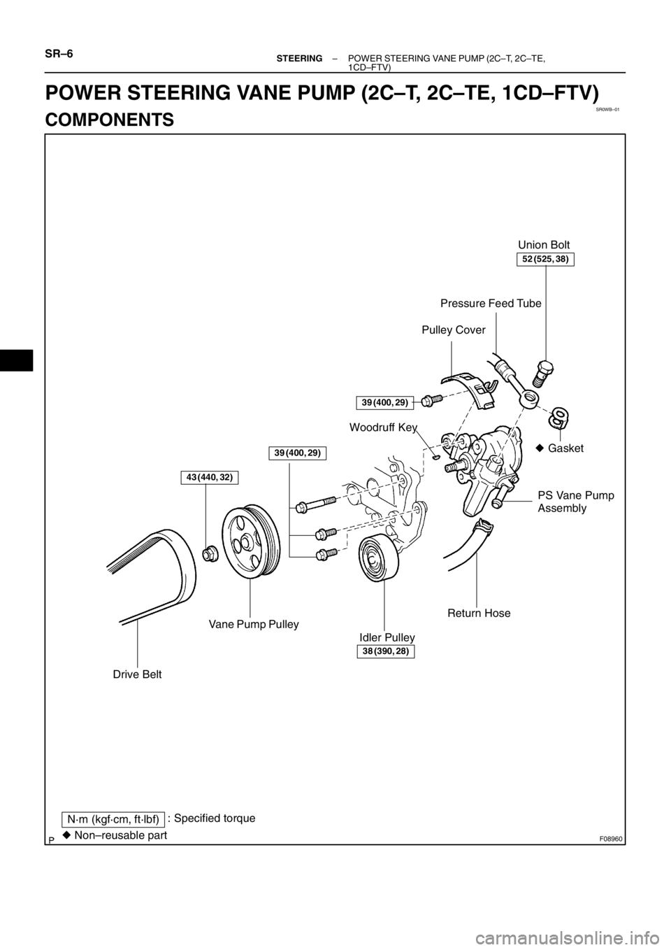
Page 206 of 349
SR0WB–01
F08960
� Gasket Union Bolt
Pressure Feed Tube
PS Vane Pump
Assembly Woodruff Key
Vane Pump Pulley
Drive Belt
Idler PulleyReturn Hose
N·m (kgf·cm, ft·lbf): Specified torque
� Non–reusable part
Pulley Cover
43 (440, 32)
39 (400, 29)
39 (400, 29)
38 (390, 28)
52 (525, 38)
SR–6– STEERINGPOWER STEERING VANE PUMP (2C–T, 2C–TE,
1CD–FTV)
POWER STEERING VANE PUMP (2C–T, 2C–TE, 1CD–FTV)
COMPONENTS
Page 207 of 349
F03716
N·m (kgf·cm, ft·lbf): Specified torque
� Non–reusable partPressure Port Union
� Shorter Straight Pin
� O–Ring � Snap Ring � O–Ring
� Longer Straight PinSide Front Plate
Flow Control Valve
Spring
� Oil Seal
Front HousingSuction Port UnionVane Pump
Shaft
Power steering fluid
69 (700, 51)
13 (130, 9)
� O–Ring
� O–Ring
� O–Ring � Snap Ring
Cam Ring
Rear Housing
Wave Washer � O–Ring
Side Rear Plate Vane Pump RotorVane Plate
x10
– STEERINGPOWER STEERING VANE PUMP (2C–T, 2C–TE,
1CD–FTV)SR–7
Page 208 of 349
SR0WC–01
F03730
F04155
SST
SR–8– STEERINGPOWER STEERING VANE PUMP (2C–T, 2C–TE,
1CD–FTV)
REMOVAL
1. REMOVE DRIVE BELT
(a) Loosen the idler pulley set nut.
(b) Loosen the belt tension adjusting bolt, and remove the
drive belt.
2. REMOVE VANE PUMP PULLEY
(a) Using SST to stop the pulley rotating, remove the pulley
set nut.
SST 09960–10010 (09962–01000, 09963–01000)
(b) Remove the pulley and woodruff key from the vane pump
shaft.
3. DISCONNECT RETURN HOSE
Remove the clip and disconnect return the hose.
4. DISCONNECT PRESSURE FEED TUBE
Remove the union bolt and gasket, and disconnect the pres-
sure feed tube.
5. REMOVE PS VANE PUMP ASSEMBLY
Remove the 3 bolts and PS vane pump assembly.
6. REMOVE PULLEY COVER
Remove the bolt and pulley cover.
Page 209 of 349
SR–9
DISASSEMBLY
NOTICE:
When using a vise, do not overtighten it.
1. MEASURE PS VANE PUM")
SR0WD–01
F03717
F03718
F03719
Vinyl Tape
– STEERINGPOWER STEERING VANE PUMP (2C–T, 2C–TE,
1CD–FTV)SR–9
DISASSEMBLY
NOTICE:
When using a vise, do not overtighten it.
1. MEASURE PS VANE PUMP ROTATING TORQUE
(a) Check that the pump rotates smoothly without abnormal
noise.
(b) Temporarily install the vane pump pulley set nut.
(c) Using a torque wrench, check the pump rotating torque.
Rotating torque:
0.3 N·m (2.8 kgf·cm, 2.4 in.·lbf) or less
2. REMOVE SUCTION PORT UNION
(a) Remove the bolt and suction port union.
(b) Remove the O–ring from the union.
3. REMOVE PRESSURE PORT UNION
(a) Remove the pressure port union.
(b) Remove the O–ring from the union.
4. REMOVE FLOW CONTROL VALVE AND SPRING
5. REMOVE REAR HOUSING, WAVE WASHER AND SIDE
REAR PLATE
(a) Using 2 screwdrivers, remove the snap ring.
(b) To prevent oil seal lip damage, wind vinyl tape on the ser-
rated part of the vane pump shaft.
(c) Using a plastic hammer, tap out the rear housing, wave
washer and side rear plate.
(d) Remove the O–ring from the rear housing.
(e) Remove the O–ring from the side rear plate.
6. REMOVE CAM RING AND 10 VANE PLATES
NOTICE:
Be careful not to drop the plate.
7. REMOVE VANE PUMP SHAFT WITH VANE PUMP RO-
TOR AND SIDE FRONT PLATE
8. REMOVE VANE PUMP ROTOR AND SIDE FRONT
PLATE
(a) Using a screwdriver, remove the snap ring from the vane
pump shaft.
(b) Remove the vane pump rotor and side front plate.
(c) Remove the 2 O–rings from the side front plate.
9. REMOVE SHORTER STRAIGHT PIN
Using pliers, remove the shorter straight pin from the side front
plate.
Page 210 of 349
SR–10– STEERINGPOWER STEERING VANE PUMP (2C–T, 2C–TE,
1CD–FTV)
10. REMOVE LONGER STRAIGHT PIN
Using pliers, remove the longer straight pin from the front hous-
ing.
Page 211 of 349
SR–")
F01876
Bushing
Front
Housing Vane Pump
Shaft
SR0WE–01
Z06061
Thickness
Height
Length
R10282
Feeler Gauge
F01319
Inscribed Mark
– STEERINGPOWER STEERING VANE PUMP (2C–T, 2C–TE,
1CD–FTV)SR–11
INSPECTION
NOTICE:
When using a vise, do not overtighten it.
1. MEASURE OIL CLEARANCE BETWEEN VANE PUMP
SHAFT AND BUSHING
Using a micrometer and caliper gauge, measure the oil clear-
ance.
Standard clearance:
0.01 – 0.03 mm (0.0004 – 0.0012 in.)
Maximum clearance: 0.07 mm (0.0028 in.)
If it is more than the maximum, replace the front housing and
vane pump shaft.
2. INSPECT VANE PUMP ROTOR AND VANE PLATES
(a) Using a micrometer, measure the height, thickness and
length of the 10 plates.
Minimum height: 8.1 mm (0.319 in.)
Minimum thickness: 1.797 mm (0.0708 in.)
Minimum length: 14.988 mm (0.5901 in.)
(b) Using a feeler gauge, measure the clearance between
the rotor groove and plate.
Maximum clearance: 0.03 mm (0.0012 in.)
If it is more than the maximum, replace the plate and/or rotor
with the one having the same mark stamped on the cam ring.
Inscribed mark: 1, 2, 3, 4 or None
Page 212 of 349

HINT:
There are 5 vane plate lengths with the following rotor and cam
ring")
F03747
F04785
Compressed Air
F01318
Inscribed Mark
SR–12– STEERINGPOWER STEERING VANE PUMP (2C–T, 2C–TE,
1CD–FTV)
HINT:
There are 5 vane plate lengths with the following rotor and cam
ring marks:
Rotor and cam
ring markVane plate part
numberVane plate length
mm (in.)
None44345–1201014.996 – 14.998
(0.59039 – 0.59047)
144345–1202014.994 – 14.996
(0.59032 – 0.59039)
244345–1203014.992 – 14.994
(0.59024 – 0.59032)
344345–1204014.990 – 14.992
(0.59016 – 0.59024)
444345–1205014.988 – 14.990
(0.59008 – 0.59016)
3. INSPECT FLOW CONTROL VALVE
(a) Coat the valve with power steering fluid and check that it
falls smoothly into the valve hole by its own weight.
(b) Check the flow control valve for leakage. Close one of the
holes and apply compressed air 392 – 490 kPa (4 – 5
kgf/cm
2, 57 – 71 psi) into the opposite side hole, and con-
firm that air does not come out from the end hole.
If necessary, replace the valve with the one having the same let-
ter as inscribed on the front housing.
Inscribed mark: A, B, C, D, E or F


REMOVAL
1. REMOVE DRIVE BELT
(a) Loosen the idler pulley set nut.
(b) Loosen the belt tension adj")

10. REMOVE LONGER STRAIGHT PIN
Using pliers, remove the longer straight pin from the front hous-
ing.")