1999 SUZUKI GRAND VITARA throttle cable
[x] Cancel search: throttle cablePage 164 of 656

ENGINE GENERAL INFORMATION AND DIAGNOSIS (H27 ENGINE) 6-1-3
General Information
Statement of Cleanliness and Care
An automobile engine is a combination of many machined, honed, polished and lapped surfaces with tolerances
that are measured in the thousands of an millimeter (ten thousands of inch). Accordingly, when any internal
engine parts are serviced, care and cleanliness are important. Throughout this section, it should be understood
that proper cleaning and protection of machined surfaces and friction areas is part of the repair procedure. This
is considered standard shop practice even if not specifically stated.
A liberal coating of engine oil should be applied to friction areas during assembly to protect and lubricate the
surface on initial operation.
Whenever valve train components, pistons, piston rings, connecting rods, rod bearings and crankshaft jour-
nal bearings are removed for service, they should be retained in order. At the time of installation, they should
be installed in the same locations and with the same mating surfaces as when removed.
Battery cables should be disconnected before any major work is performed on the engine. Failure to discon-
nect cables may result in damage to wire harness or other electrical parts.
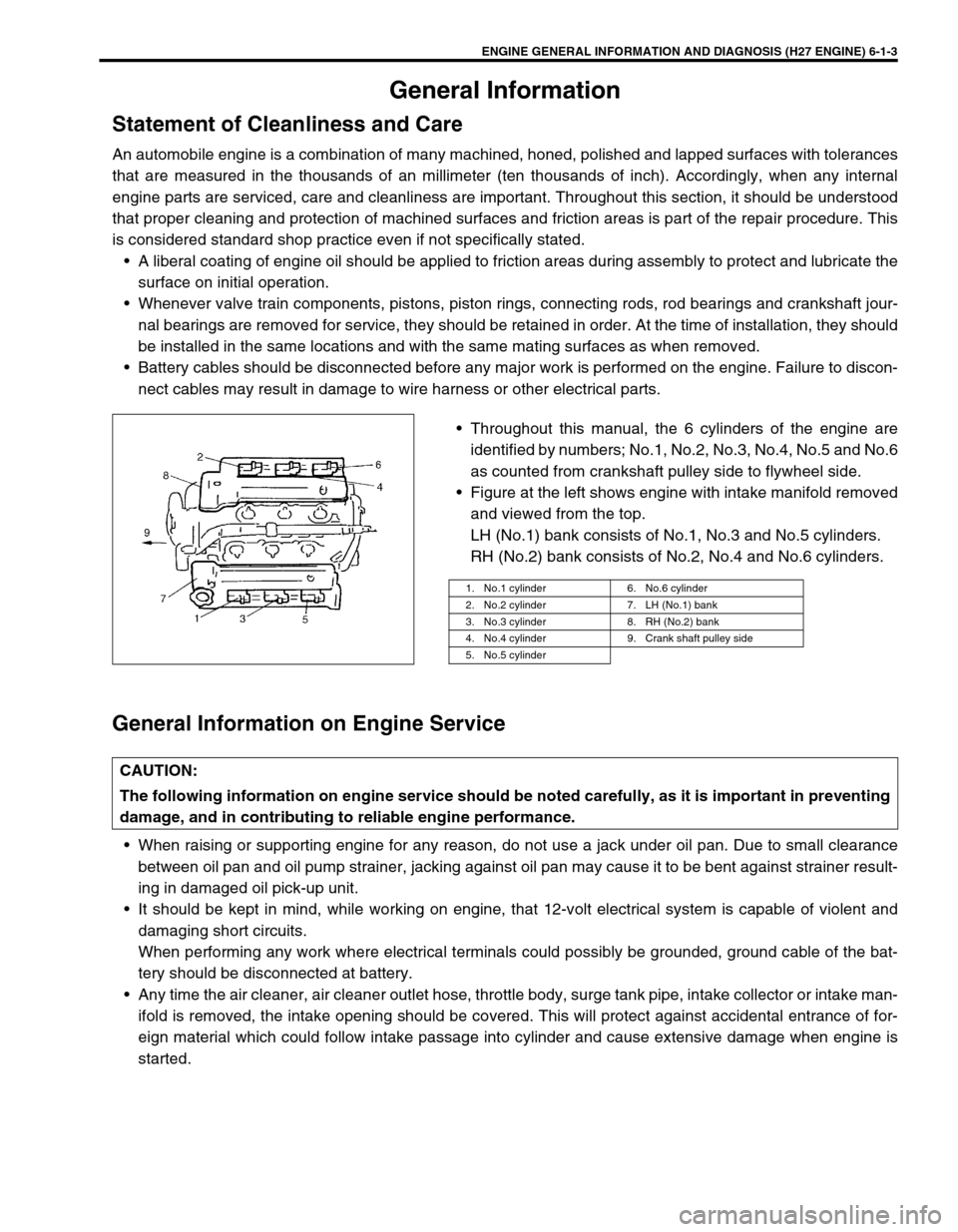
Throughout this manual, the 6 cylinders of the engine are
identified by numbers; No.1, No.2, No.3, No.4, No.5 and No.6
as counted from crankshaft pulley side to flywheel side.
Figure at the left shows engine with intake manifold removed
and viewed from the top.
LH (No.1) bank consists of No.1, No.3 and No.5 cylinders.
RH (No.2) bank consists of No.2, No.4 and No.6 cylinders.
General Information on Engine Service
When raising or supporting engine for any reason, do not use a jack under oil pan. Due to small clearance
between oil pan and oil pump strainer, jacking against oil pan may cause it to be bent against strainer result-
ing in damaged oil pick-up unit.
It should be kept in mind, while working on engine, that 12-volt electrical system is capable of violent and
damaging short circuits.
When performing any work where electrical terminals could possibly be grounded, ground cable of the bat-
tery should be disconnected at battery.
Any time the air cleaner, air cleaner outlet hose, throttle body, surge tank pipe, intake collector or intake man-
ifold is removed, the intake opening should be covered. This will protect against accidental entrance of for-
eign material which could follow intake passage into cylinder and cause extensive damage when engine is
started.
1. No.1 cylinder 6. No.6 cylinder
2. No.2 cylinder 7. LH (No.1) bank
3. No.3 cylinder 8. RH (No.2) bank
4. No.4 cylinder 9. Crank shaft pulley side
5. No.5 cylinder
CAUTION:
The following information on engine service should be noted carefully, as it is important in preventing
damage, and in contributing to reliable engine performance.
Page 174 of 656

ENGINE GENERAL INFORMATION AND DIAGNOSIS (H27 ENGINE) 6-1-13
STEP 2. DIAGNOSTIC TROUBLE CODE (DTC)/FREEZE FRAME DATA CHECK
First, check DTC, referring to “DIAGNOSTIC TROUBLE CODE CHECK” in this section. If DTC is indicated,
record DTC and freeze frame data.
After that clear DTC referring to “DIAGNOSTIC TROUBLE CODE CLEARANCE” in this section. DTC indicates
malfunction that occurred in the system but does not indicate whether it exists now or it occurred in the past and
the normal condition has been restored now. To check which case applies, check the symptom in question
according to Step 5 and recheck DTC according to Step 6, 7.
Attempt to diagnose a trouble based on DTC in this step only or failure to clear the DTC (including pending DTC)
in this step will lead to incorrect diagnosis, trouble diagnosis of a normal circuit or difficulty in troubleshooting.
STEP 3. and 4. VISUAL INSPECTION
Be sure to perform visual check of the following items that support proper function of the engine.
STEP 5. TROUBLE SYMPTOM CONFIRMATION
Based on information obtained in Step 1 “CUSTOMER COMPLAINT ANALYSIS” and Step 2 “DTC/FREEZE
FRAME DATA CHECK”, confirm trouble symptoms. Also, reconfirm DTC according to “DTC CONFIRMATION
PROCEDURE” described in each “DTC FLOW TABLE”.NOTE:
For A/T vehicle, if only DTC P0705, P0715, P0720, P0741, P0743, P0751, P0753, P0756, P0758, or P1875
is indicated in this step, proceed to “DIAGNOSIS” in SECTION 7B1.
INSPECTION ITEM REFERRING SECTION
• Engine oil - - - - - level, leakage
• Engine coolant - - - - - level, leakage
• Fuel - - - - - level, leakage
• A/T fluid - - - - - level, leakage
• Air cleaner element - - - - - dirt, clogging
• Battery - - - - - fluid level, corrosion of terminal
• Water pump belt and/or cooling fan belt - - - - - tension, damage
• Accelerator cable - - - - - play, installation
• A/T throttle cable - - - - - play, installation
• Vacuum hoses of air intake system
- - - - - disconnection, looseness, deterioration, bend
• Connectors of electric wire harness - - - - - disconnection, friction
• Fuses - - - - - burning
• Parts - - - - - installation, bolt - - - - - looseness
• Parts - - - - - deformation
• Other parts that can be checked visually
• Also check following items at engine start, if possible
– Malfunction indicator lamp - - - - - operation
– Charge warning lamp - - - - - operation
– Engine oil pressure warning lamp - - - - - operation
– Engine coolant temp. meter - - - - - operation
– Fuel lever meter - - - - - operation
– Abnormal air being inhaled from air intake system
– Exhaust system - - - - - leakage of exhaust gas, noise
– Other parts that can be checked visuallySECTION 0B
SECTION 0B
SECTION 0B
SECTION 0B
SECTION 0B
SECTION 0B
SECTION 6C
SECTION 6E2
SECTION 6E2
SECTION 6A2
SECTION 8
SECTION 6-1
SECTION 6H
SECTION 8/6A2
SECTION 8
SECTION 8
Page 179 of 656
![SUZUKI GRAND VITARA 1999 2.G Owners Manual 6-1-18 ENGINE GENERAL INFORMATION AND DIAGNOSIS (H27 ENGINE)
[Without using scan tool]
1) Turn the ignition switch OFF position.
2) Disconnect battery negative cable for specified time below to
erase SUZUKI GRAND VITARA 1999 2.G Owners Manual 6-1-18 ENGINE GENERAL INFORMATION AND DIAGNOSIS (H27 ENGINE)
[Without using scan tool]
1) Turn the ignition switch OFF position.
2) Disconnect battery negative cable for specified time below to
erase](/manual-img/20/7583/w960_7583-178.png)
6-1-18 ENGINE GENERAL INFORMATION AND DIAGNOSIS (H27 ENGINE)
[Without using scan tool]
1) Turn the ignition switch OFF position.
2) Disconnect battery negative cable for specified time below to
erase diagnostic trouble code stored in ECM memory and
reconnect it.
Time required to erase DTC:
Diagnostic Trouble Code (DTC) Table
Ambient
temperatureTime to cut power to ECM
Over 0°C (32°F) 30 sec. or longer
Under 0°C
(32°F)Not specifiable.
Select a place with higher than 0°C
(32°F) temperature.
DTC NO. DETECTED ITEMDETECTING CONDITION
(DTC will set when detecting : )MIL
(vehicle
without
monitor
connector)MIL
(vehicle
with
monitor
connector)
P0100
(No.34)
Mass air flow circuit malfunc-
tionSensor output too low
1 driving
cycle1 driving
cycle
P0100
(No.33)Sensor output too high
P0110
(No.25)
Intake air temp. circuit mal-
functionIntake air temp. circuit low input
1 driving
cycle1 driving
cycle
P0110
(No.23)Intake air temp. circuit high input
P0115
(No.15)
Engine coolant temp. circuit
malfunctionEngine coolant temp. circuit low input
1 driving
cycle1 driving
cycle
P0115
(No.14)Engine coolant temp. circuit high input
P0120
(No.22)
Throttle position circuit mal-
functionThrottle position circuit low input
1 driving
cycle1 driving
cycle
P0120
(No.21)Throttle position circuit high input
P0121Throttle position circuit perfor-
mance problemPoor performance of TP sensor2 driving
cyclesNot
applicable
*P0130HO2S circuit malfunction
(Bank 1 - Sensor 1)Min. output voltage of HO2S-1 is
higher than specification.
2 driving
cyclesNot
applicable Min. output voltage of HO2S-1 is
lower than specification.
Output voltage of HO2S-1 fails to go
above specification.
**P0130
(No.13)HO2S (Bank 1 - Sensor 1) no
activity detectedOutput voltage of HO2S-1 fails to go
above specification (or HO2S-1 cir-
cuit open).2 driving
cycles2 driving
cycles
Page 218 of 656

ENGINE GENERAL INFORMATION AND DIAGNOSIS (H27 ENGINE) 6-1-57
TROUBLESHOOTING
Fig. for Steps 4 and 5Step Action Yes No
1 Was “ENGINE DIAG. FLOW TABLE” performed? Go to Step 2. Go to “ENGINE
DIAG. FLOW TABLE”
in this section.
2 Is there a DTC related to TP sensor (DTC P0120)? Go to applicable DTC
Diag. Flow Table.Go to Step 3.
3 Do you have SUZUKI scan tool ? Go to Step 4. Go to Step 5.
4 Check TP sensor and its circuit (using SUZUKI
scan tool) :
1) Turn ignition switch OFF and connect SUZUKI
scan tool to DLC.
2) Turn ignition switch ON and check TP sensor
output voltage when throttle valve is at idle posi-
tion and fully opened.
Does voltage vary within specified value linearly as
shown in the figure?Substitute a known-good
ECM (PCM) and recheck.Go to Step 6.
5 Check TP sensor and its circuit (not using SUZUKI
scan tool) :
1) Turn ignition switch ON.
2) Check voltage at terminal C51-3-9 of ECM con-
nector connected, when throttle valve is at idle
position and fully opened.
Does voltage vary within specified value linearly as
shown in the figure?If voltmeter was used,
check terminal C51-3-9 for
poor connection.
If OK, substitute a known-
good ECM (PCM) and
recheck.Go to Step 6.
6 Check TP sensor :
1) Turn ignition switch OFF.
2) Disconnect TP sensor connector.
3) Check for proper connection to TP sensor at
each terminal.
4) If OK, check TP sensor for resistance referring
to “TP SENSOR” in Section 6E2.
Is check result satisfactory?High resistance in “GRY/
RED”, “RED/GRN” or
“GRY/YEL” circuit.
If wire and connection are
OK, substitute a known-
good ECM (PCM) and
recheck.Replace TP sensor.
1. Voltage
2. Throttle opening
3. At idle position
4. Fully open
Page 288 of 656

ENGINE MECHANICAL (H27 ENGINE) 6A2-1
6A2
SECTION 6A2
ENGINE MECHANICAL (H27 ENGINE)
CONTENTS
On-Vehicle Service........................................6A2-2
Throttle Body and Intake Manifold .............. 6A2-2
Exhaust Manifold ......................................... 6A2-9
LH (No.1) Bank 2nd Timing Chain
and Chain Tensioner ................................. 6A2-13
Camshaft and Valve Lash Adjuster ........... 6A2-14
Valves and Cylinder Heads ....................... 6A2-17
Piston, Piston Rings, Connecting Rodsand Cylinders ............................................ 6A2-21
Unit Repair Overhaul .................................. 6A2-26
Engine Assembly ...................................... 6A2-26
Main Bearings, Crankshaft
and Cylinder Block .................................... 6A2-30
Special Tool ................................................. 6A2-36
WARNING:
For vehicles equipped with Supplemental Restraint (Air Bag) System:
Service on and around the air bag system components or wiring must be performed only by an
authorized SUZUKI dealer. Refer to “Air Bag System Components and Wiring Location View” under
“General Description” in air bag system section in order to confirm whether you are performing ser-
vice on or near the air bag system components or wiring. Please observe all WARNINGS and “Ser-
vice Precautions” under “On-Vehicle Service” in air bag system section before performing service
on or around the air bag system components or wiring. Failure to follow WARNINGS could result in
unintentional activation of the system or could render the system inoperative. Either of these two
conditions may result in severe injury.
Technical service work must be started at least 90 seconds after the ignition switch is turned to the
“LOCK” position and the negative cable is disconnected from the battery. Otherwise, the system
may be activated by reserve energy in the Sensing and Diagnostic Module (SDM).
NOTE:
For the descriptions (items) not found in this section, refer to the same section of service manual
mentioned in the FOREWORD of this manual.
Whether following systems (parts) are used in the particular vehicle or not depends on specifica-
tions. Be sure to bear this in mind when performing service work.
–EGR valve
–Warm up three way catalytic converter
–Heated oxygen sensor(s)
–Three way catalytic converter
–CKP sensor
–MAP sensor
Page 291 of 656

6A2-4 ENGINE MECHANICAL (H27 ENGINE)
8) Disconnect accelerator cable (1) and A/T throttle cable (2)
(for A/T vehicle) from throttle body.
9) Disconnect water hoses (3) from throttle body.
10) Disconnect injector wire (1) coupler.
11) Disconnect brake booster hose (2) from intake manifold.
12) Disconnect couplers of TP sensor (1) and IAC valve (2).
13) Disconnect earth terminal (3) from intake collector.
14) Remove clamp bracket (4) from intake collector.
15) Disconnect couplers from manifold absolute pressure (MAP)
sensor, EVAP canister purge valve, earth terminal and EGR
valve.
16) Disconnect PCV hose from cylinder head cover.
Disconnect breather hoses from throttle body or cylinder
head cover.
17) Disconnect hoses of EVAP canister purge valve and heater.
18) Remove EGR pipe.
12
33
2
1
2
14
3
1. EVAP canister purge valve 6. PCV hose
2. EGR valve 7. Water hose
3. EGR pipe 8. Breather hose
4. EVAP canister purge valve hose 9. Earth terminal coupler
5. Heater hose
9
4
1 7
6
2
35
8
Page 295 of 656

6A2-8 ENGINE MECHANICAL (H27 ENGINE)
16) Connect water hoses (3) to throttle body.
17) Connect accelerator cable (1) and A/T throttle cable (2) (for
A/T vehicle) to throttle body.
18) Install surge tank pipe (2) to intake manifold with new gas-
kets and intake air pipe (1) to throttle body.
19) Install surge tank cover (1).
20) Install air cleaner upper case.
21) Connect coupler to intake air temp. sensor and MAF sensor.
22) Install strut tower bar (1).
23) Check to ensure that all removed parts are back in place.
Reinstall any necessary parts which have not been rein-
stalled.
24) Refill cooling system referring to “COOLING SYSTEM
FLUSH AND REFILL” in Section 6B.
25) Connect negative cable at battery.
12
33
1
2
1
Page 307 of 656

6A2-20 ENGINE MECHANICAL (H27 ENGINE)
12) Install oil pan and oil pump strainer.
Refer to “OIL PAN AND OIL PUMP STRAINER” in this sec-
tion.
13) Install cylinder head cover.
Refer to “CYLINDER HEAD COVER” in this section.
14) Install exhaust manifold.
Refer to “EXHAUST MANIFOLD” in this section.
15) Install radiator outlet pipe, radiator, cooling fan and water
hose.
Refer to “COOLING WATER PIPES OR HOSES”, “RADIA-
TOR” and “COOLING FAN AND FAN CLUTCH” in Section
6B.
16) Install throttle body and intake manifold.
Refer to “THROTTLE BODY AND INTAKE MANIFOLD” in
this section.
17) Adjust water pump drive belt tension.
Refer to “COOLING FAN BELT TENSION CHECK AND
ADJUSTMENT” in Section 6B.
18) Adjust power steering pump drive belt tension.
Refer to “POWER STEERING PUMP DRIVE BELT” in Sec-
tion 3B1.
19) Adjust accelerator cable play and A/T throttle cable play.
Refer to “ACCELERATOR CABLE ADJUSTMENT” and “A/T
THROTTLE CABLE ADJUSTMENT (A/T VEHICLE)” in Sec-
tion 6E2.
20) Check to ensure that all removed parts are back in place.
Reinstall any necessary parts which have not been rein-
stalled.
21) Refill engine with engine oil, referring to “ENGINE OIL
CHANGE” in Section 0B.
22) Refill cooling system referring to “COOLING SYSTEM
FLUSH AND REFILL” in Section 6B.
23) Refill front differential housing with gear oil if drained, refer-
ring to “MAINTENANCE SERVICE” in Section 7E.
24) Connect negative cable at battery.
25) Check ignition timing and adjust as necessary, referring to
“IGNITION TIMING CHECK AND ADJUSTMENT” in Section
6F2.
26) Verify that there is no fuel leakage, water leakage, oil leak-
age and exhaust gas leakage at each connection.
27) Check wheel alignment, referring to “STEERING ANGLE” in
Section 3A.