1999 SUZUKI GRAND VITARA Gear oil
[x] Cancel search: Gear oilPage 74 of 656
POWER STEERING (P/S) SYSTEM 3B1-3
Hydraulic Pressure in P/S Circuit
Hydraulic pressure check
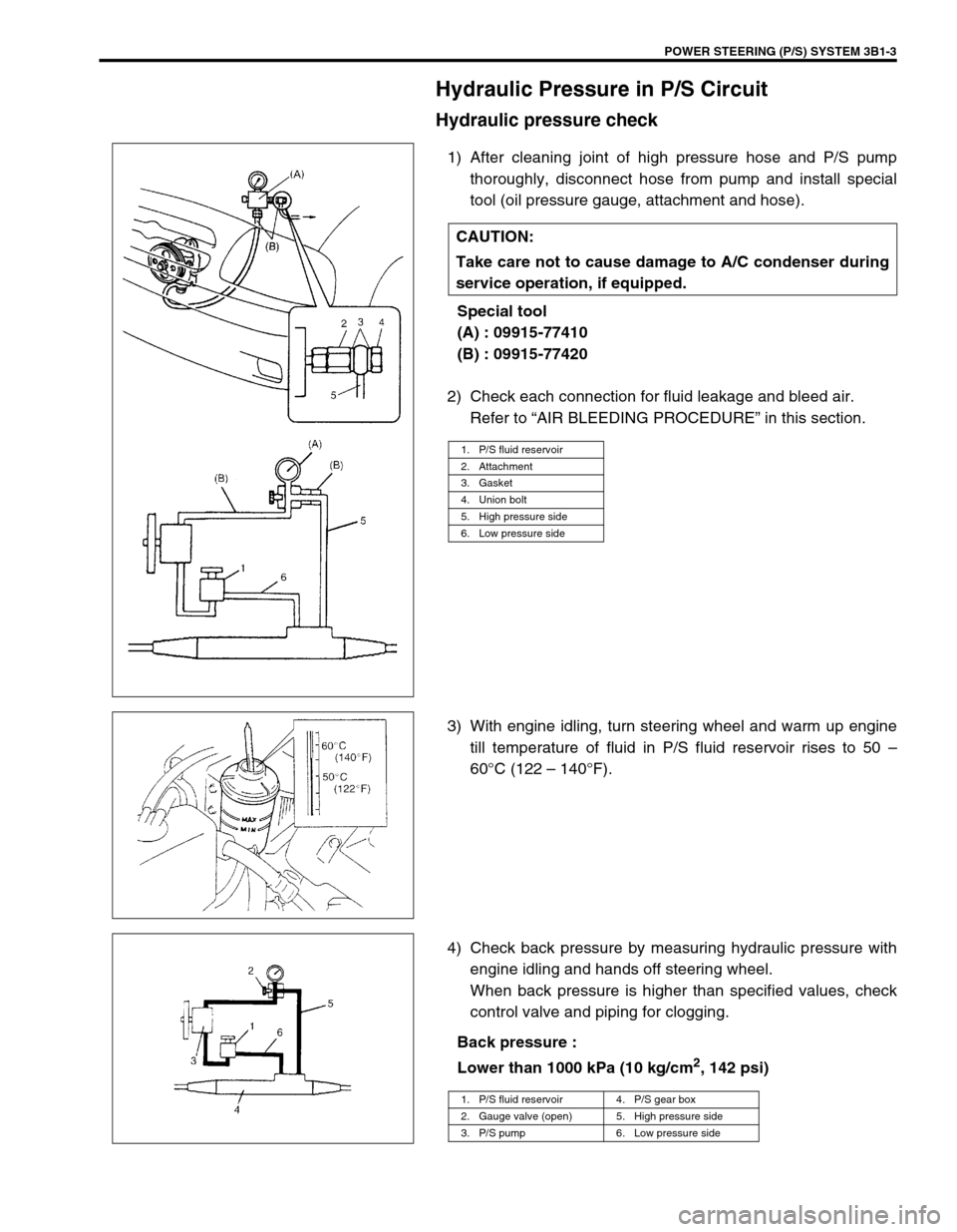
1) After cleaning joint of high pressure hose and P/S pump
thoroughly, disconnect hose from pump and install special
tool (oil pressure gauge, attachment and hose).
Special tool
(A) : 09915-77410
(B) : 09915-77420
2) Check each connection for fluid leakage and bleed air.
Refer to “AIR BLEEDING PROCEDURE” in this section.
3) With engine idling, turn steering wheel and warm up engine
till temperature of fluid in P/S fluid reservoir rises to 50 –
60°C (122 – 140°F).
4) Check back pressure by measuring hydraulic pressure with
engine idling and hands off steering wheel.
When back pressure is higher than specified values, check
control valve and piping for clogging.
Back pressure :
Lower than 1000 kPa (10 kg/cm
2, 142 psi) CAUTION:
Take care not to cause damage to A/C condenser during
service operation, if equipped.
1. P/S fluid reservoir
2. Attachment
3. Gasket
4. Union bolt
5. High pressure side
6. Low pressure side
1. P/S fluid reservoir 4. P/S gear box
2. Gauge valve (open) 5. High pressure side
3. P/S pump 6. Low pressure side
Page 75 of 656
3B1-4 POWER STEERING (P/S) SYSTEM
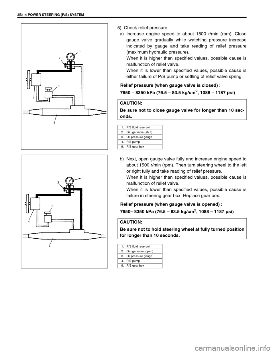
5) Check relief pressure.
a) Increase engine speed to about 1500 r/min (rpm). Close
gauge valve gradually while watching pressure increase
indicated by gauge and take reading of relief pressure
(maximum hydraulic pressure).
When it is higher than specified values, possible cause is
malfunction of relief valve.
When it is lower than specified values, possible cause is
either failure of P/S pump or settling of relief valve spring.
Relief pressure (when gauge valve is closed) :
7650 – 8350 kPa (76.5 – 83.5 kg/cm
2, 1088 – 1187 psi)
b) Next, open gauge valve fully and increase engine speed to
about 1500 r/min (rpm). Then turn steering wheel to the left
or right fully and take reading of relief pressure.
When it is higher than specified values, possible cause is
malfunction of relief valve.
When it is lower than specified values, possible cause is
failure in steering gear box. Replace gear box.
Relief pressure (when gauge valve is opened) :
7650– 8350 kPa (76.5 – 83.5 kg/cm
2, 1088 – 1187 psi) CAUTION:
Be sure not to close gauge valve for longer than 10 sec-
onds.
1. P/S fluid reservoir
2. Gauge valve (shut)
3. Oil pressure gauge
4. P/S pump
5. P/S gear box
CAUTION:
Be sure not to hold steering wheel at fully turned position
for longer than 10 seconds.
1. P/S fluid reservoir
2. Gauge valve (open)
3. Oil pressure gauge
4. P/S pump
5. P/S gear box
Page 93 of 656

3E-4 REAR SUSPENSION
5) Apply grease “A” to axle shaft inner oil seal lip as shown in
the figure.
“A” : Grease 99000-25010
6) Apply water tight sealant “B” to mating surfaces of brake
back plate and rear axle hub (2).
“B” : Water tight sealant 99000-31110
7) Install rear axle shaft to rear axle housing and tighten bear-
ing retainer nuts to specified torque.
Rear axle shaft length “L”
Left side : 700.5 mm (27.6 in.)
Right side : 769.5 mm (30.3 in.)
Tightening torque
Bearing retainer nut (a) : 50 N·m (5.0 kg-m, 36.5 lb-ft)
8) Tighten wheel speed sensor bolt to specified torque (if
equipped with ABS).
Tightening torque
Wheel speed sensor bolt (b) : 21 N·m (2.1 kg-m, 15.5 lb-ft)
9) Refill rear axle housing with new specified gear oil.
Refer to “MAINTENANCE SERVICE” in Section 7F.
10) Install brake drum. Refer to “BRAKE DRUM” in Section 5C.
1. Axle housing
NOTE:
When installing rear axle shaft, be careful not to cause
damage to oil seal lip in axle housing.
(b)
Page 95 of 656

3E-6 REAR SUSPENSION
5) Apply thread lock cement to thread of propeller shaft flange
bolt if reused. Install propeller shaft to joint flange aligning
match marks and torque flange nuts to specification.
“A” : Cement 99000-32110
Tightening torque
Propeller shaft nut (a) :
60 N·m (6.0 kg-m, 43.5 lb-ft)
Tightening Torque Specification
Required Service Material
Fastening partTightening torque
Nm kg-m lb-ft
Shock absorber nut 29 2.9 21.0
Shock absorber lower nut 85 8.5 61.5
Lower rod bolt and nut 100 10.0 72.5
Upper rod bolt and nut 100 10.0 72.5
Lateral rod bolt 100 10.0 72.5
Differential carrier bolt 55 5.5 40.0
Propeller shaft nut 60 6.0 43.5
Brake pipe flare nut 16 1.6 11.5
Bearing retainer nut 50 5.0 36.5
Differentiation gear oil filler & drain plug (filler plug) 50 5.0 36.5
Differentiation gear oil filler & drain plug (drain plug) 27 2.7 16.0
Wheel nut 100 10.0 72.5
Wheel speed sensor bolt 21 2.1 15.5
MaterialRecommended SUZUKI product
(Part Number)Use
Lithium grease SUZUKI SUPER GREASE A
(99000-25010)Oil seal lip
Brake fluid DOT 3Brake reservoir tank
Sealant SUZUKI BOND NO. 1215
(99000-31110)Joint seam of axle and brake back plate
Joint seam of bearing retainer and brake
back plate
Joint seam of differential carrier and axle
housing
Drain plug
Mating surface of oil seal and axle housing
Gear oil For gear oil information, refer to Section 7FDifferential gear (Rear axle housing)
Thread lock
cementTHREAD LOCK CEMENT SUPER 1322
(99000-32110)Rear propeller shaft flange bolts
Page 123 of 656
5C-6 PARKING AND REAR BRAKE
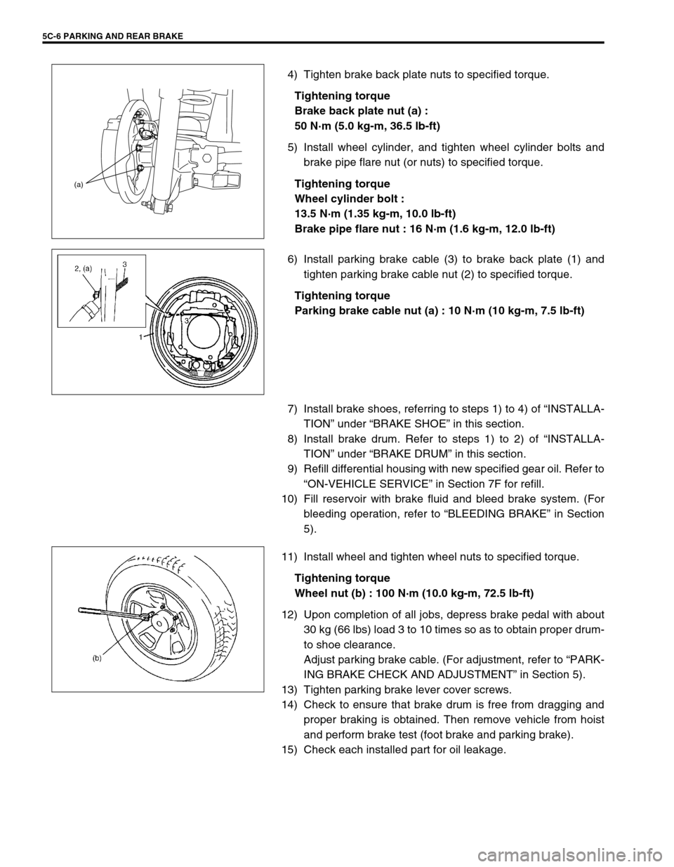
4) Tighten brake back plate nuts to specified torque.
Tightening torque
Brake back plate nut (a) :
50 N·m (5.0 kg-m, 36.5 lb-ft)
5) Install wheel cylinder, and tighten wheel cylinder bolts and
brake pipe flare nut (or nuts) to specified torque.
Tightening torque
Wheel cylinder bolt :
13.5 N·m (1.35 kg-m, 10.0 lb-ft)
Brake pipe flare nut : 16 N·m (1.6 kg-m, 12.0 lb-ft)
6) Install parking brake cable (3) to brake back plate (1) and
tighten parking brake cable nut (2) to specified torque.
Tightening torque
Parking brake cable nut (a) : 10 N·m (10 kg-m, 7.5 lb-ft)
7) Install brake shoes, referring to steps 1) to 4) of “INSTALLA-
TION” under “BRAKE SHOE” in this section.
8) Install brake drum. Refer to steps 1) to 2) of “INSTALLA-
TION” under “BRAKE DRUM” in this section.
9) Refill differential housing with new specified gear oil. Refer to
“ON-VEHICLE SERVICE” in Section 7F for refill.
10) Fill reservoir with brake fluid and bleed brake system. (For
bleeding operation, refer to “BLEEDING BRAKE” in Section
5).
11) Install wheel and tighten wheel nuts to specified torque.
Tightening torque
Wheel nut (b) : 100 N·m (10.0 kg-m, 72.5 lb-ft)
12) Upon completion of all jobs, depress brake pedal with about
30 kg (66 lbs) load 3 to 10 times so as to obtain proper drum-
to shoe clearance.
Adjust parking brake cable. (For adjustment, refer to “PARK-
ING BRAKE CHECK AND ADJUSTMENT” in Section 5).
13) Tighten parking brake lever cover screws.
14) Check to ensure that brake drum is free from dragging and
proper braking is obtained. Then remove vehicle from hoist
and perform brake test (foot brake and parking brake).
15) Check each installed part for oil leakage.
(a)
Page 307 of 656
6A2-20 ENGINE MECHANICAL (H27 ENGINE)
12) Install oil pan and oil pump strainer.
Refer to “OIL PAN AND OIL PUMP STRAINER” in this sec-
tion.
13) Install cylinder head cover.
Refer to “CYLINDER HEAD COVER” in this section.
14) Install exhaust manifold.
Refer to “EXHAUST MANIFOLD” in this section.
15) Install radiator outlet pipe, radiator, cooling fan and water
hose.
Refer to “COOLING WATER PIPES OR HOSES”, “RADIA-
TOR” and “COOLING FAN AND FAN CLUTCH” in Section
6B.
16) Install throttle body and intake manifold.
Refer to “THROTTLE BODY AND INTAKE MANIFOLD” in
this section.
17) Adjust water pump drive belt tension.
Refer to “COOLING FAN BELT TENSION CHECK AND
ADJUSTMENT” in Section 6B.
18) Adjust power steering pump drive belt tension.
Refer to “POWER STEERING PUMP DRIVE BELT” in Sec-
tion 3B1.
19) Adjust accelerator cable play and A/T throttle cable play.
Refer to “ACCELERATOR CABLE ADJUSTMENT” and “A/T
THROTTLE CABLE ADJUSTMENT (A/T VEHICLE)” in Sec-
tion 6E2.
20) Check to ensure that all removed parts are back in place.
Reinstall any necessary parts which have not been rein-
stalled.
21) Refill engine with engine oil, referring to “ENGINE OIL
CHANGE” in Section 0B.
22) Refill cooling system referring to “COOLING SYSTEM
FLUSH AND REFILL” in Section 6B.
23) Refill front differential housing with gear oil if drained, refer-
ring to “MAINTENANCE SERVICE” in Section 7E.
24) Connect negative cable at battery.
25) Check ignition timing and adjust as necessary, referring to
“IGNITION TIMING CHECK AND ADJUSTMENT” in Section
6F2.
26) Verify that there is no fuel leakage, water leakage, oil leak-
age and exhaust gas leakage at each connection.
27) Check wheel alignment, referring to “STEERING ANGLE” in
Section 3A.
Page 389 of 656
6F2-6 IGNITION SYSTEM (FOR H27 ENGINE)
Ignition Spark Check
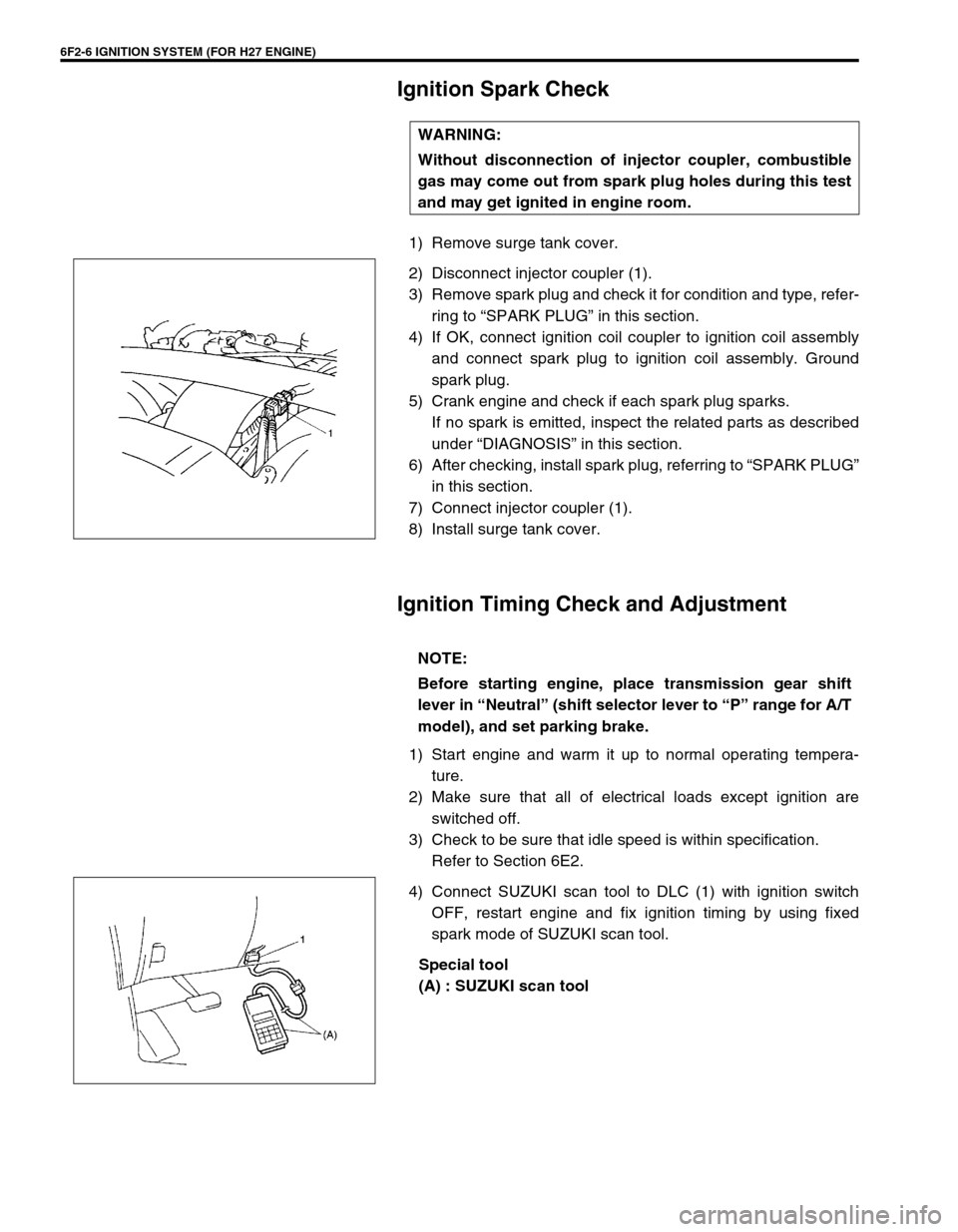
1) Remove surge tank cover.
2) Disconnect injector coupler (1).
3) Remove spark plug and check it for condition and type, refer-
ring to “SPARK PLUG” in this section.
4) If OK, connect ignition coil coupler to ignition coil assembly
and connect spark plug to ignition coil assembly. Ground
spark plug.
5) Crank engine and check if each spark plug sparks.
If no spark is emitted, inspect the related parts as described
under “DIAGNOSIS” in this section.
6) After checking, install spark plug, referring to “SPARK PLUG”
in this section.
7) Connect injector coupler (1).
8) Install surge tank cover.
Ignition Timing Check and Adjustment
1) Start engine and warm it up to normal operating tempera-
ture.
2) Make sure that all of electrical loads except ignition are
switched off.
3) Check to be sure that idle speed is within specification.
Refer to Section 6E2.
4) Connect SUZUKI scan tool to DLC (1) with ignition switch
OFF, restart engine and fix ignition timing by using fixed
spark mode of SUZUKI scan tool.
Special tool
(A) : SUZUKI scan tool WARNING:
Without disconnection of injector coupler, combustible
gas may come out from spark plug holes during this test
and may get ignited in engine room.
NOTE:
Before starting engine, place transmission gear shift
lever in “Neutral” (shift selector lever to “P” range for A/T
model), and set parking brake.
Page 412 of 656
AUTOMATIC TRANSMISSION (4 A/T) 7B1-3
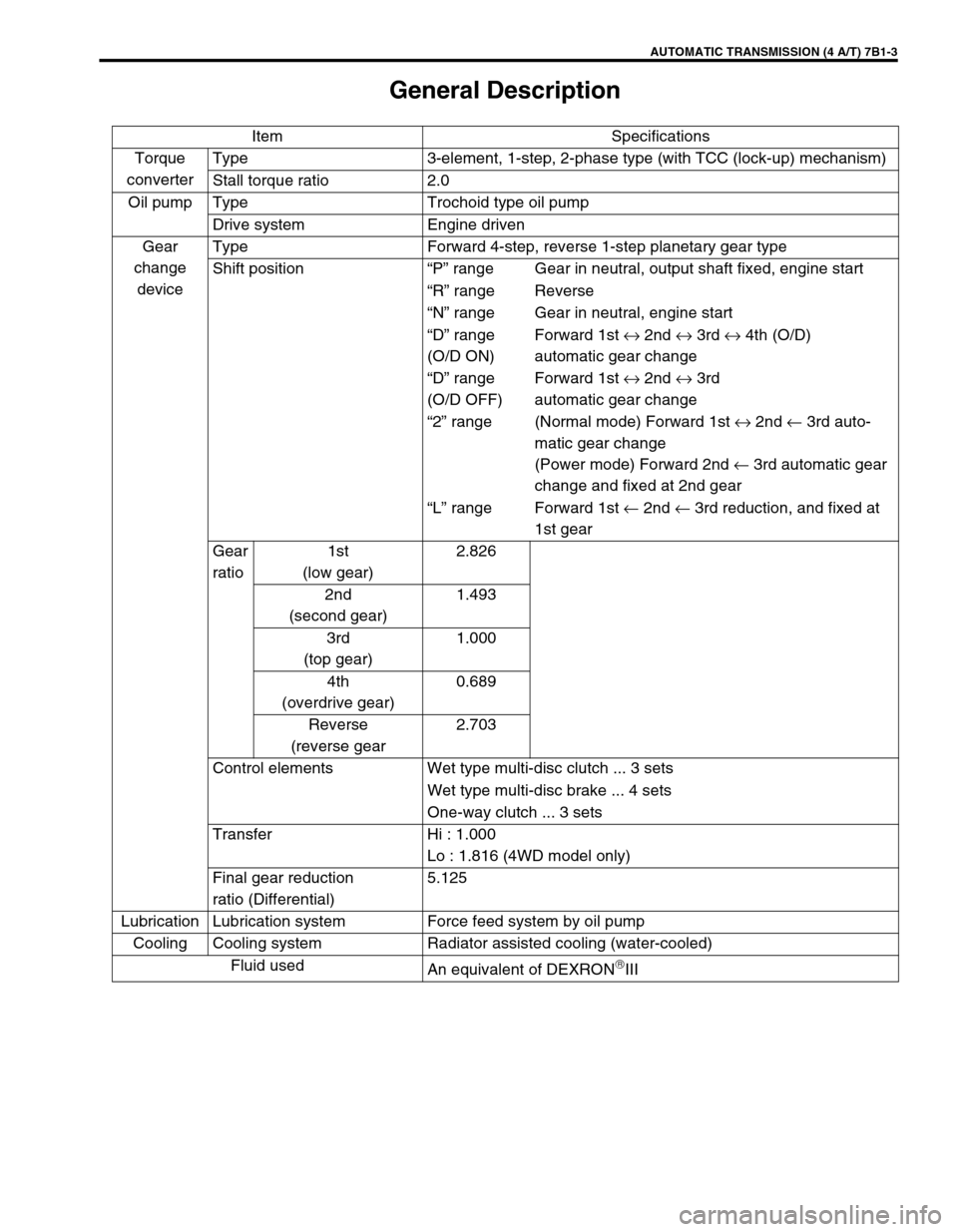
General Description
Item Specifications
Torque
converterType 3-element, 1-step, 2-phase type (with TCC (lock-up) mechanism)
Stall torque ratio 2.0
Oil pump Type Trochoid type oil pump
Drive system Engine driven
Gear
change
deviceType Forward 4-step, reverse 1-step planetary gear type
Shift position“P” range Gear in neutral, output shaft fixed, engine start
“R” range Reverse
“N” range Gear in neutral, engine start
“D” range
(O/D ON)Forward 1st ↔ 2nd ↔ 3rd ↔ 4th (O/D)
automatic gear change
“D” range
(O/D OFF)Forward 1st ↔ 2nd ↔ 3rd
automatic gear change
“2” range (Normal mode) Forward 1st ↔ 2nd ← 3rd auto-
matic gear change
(Power mode) Forward 2nd ← 3rd automatic gear
change and fixed at 2nd gear
“L” range Forward 1st ← 2nd ← 3rd reduction, and fixed at
1st gear
Gear
ratio1st
(low gear)2.826
2nd
(second gear)1.493
3rd
(top gear)1.000
4th
(overdrive gear)0.689
Reverse
(reverse gear2.703
Control elements Wet type multi-disc clutch ... 3 sets
Wet type multi-disc brake ... 4 sets
One-way clutch ... 3 sets
Transfer Hi : 1.000
Lo : 1.816 (4WD model only)
Final gear reduction
ratio (Differential)5.125
Lubrication Lubrication system Force feed system by oil pump
Cooling Cooling system Radiator assisted cooling (water-cooled)
Fluid used
An equivalent of DEXRON
III