1999 SUZUKI GRAND VITARA Gear oil
[x] Cancel search: Gear oilPage 424 of 656

AUTOMATIC TRANSMISSION (4 A/T) 7B1-15
Trouble Diagnosis Table 1
Trouble Diagnosis Table 2
TRANSMISSION FLUID
RUNNING CONDITION
4 Perform stall test, time rag test, line pressure test,
engine brake test and “P” range test referring to
“STALL TEST”, “LINE PRESSURE TEST”, “ENGINE
BRAKE TEST” and ““P” RANGE TEST” in this section.
Are the test results satisfactory?Go to Step 5. Proceed to “TROUBLE
DIAGNOSIS TABLE 3” in
this section.
5 Proceed to “TROUBLE DIAGNOSIS TABLE 2” in this
section.
Is trouble identified?Repair or replace
defective parts.Proceed to “TROUBLE
DIAGNOSIS TABLE 3” in
this section. Step Action Yes No
Condition Possible Cause Correction
TCC does not operateBrake pedal (stop lamp) switch or its circuit
faulty (H25 engine only)Refer to “DIAGNOSTIC FLOW
TABLE A-1” in this section.
4WD low switch or its circuit faulty
Engine coolant temp. sensor or its circuit faulty
Cruise control signal circuit faulty (if equipped)
Gear does not change
to 4thO/D off switch or its circuit faulty Refer to “DIAGNOSTIC FLOW
TABLE A-2” in this section.
4WD low switch or its circuit faulty
Engine coolant temp. sensor or its circuit faulty
Cruise control signal circuit faulty (if equipped)
Condition Possible Cause Correction
Low fluid pressureClogged oil pump strainer Wash strainer.
Malfunction of pressure regulator valve Overhaul valve body.
High fluid pressurePressure regulator valve Overhaul valve body.
Condition Possible Cause Correction
Unable to run in all
rangeRegulator valve stick Replace.
Clogged oil strainer Wash strainer.
Seized or broken planetary gear Repair or replace.
Faulty manual valve Replace.
Poor 1st speed run-
ning or excessive slip-
page in “D” or “2”Faulty 1–2 shift valve Replace.
Page 425 of 656
7B1-16 AUTOMATIC TRANSMISSION (4 A/T)
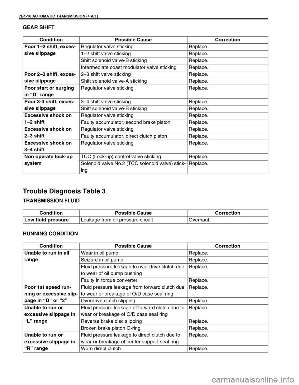
GEAR SHIFT
Trouble Diagnosis Table 3
TRANSMISSION FLUID
RUNNING CONDITION
Condition Possible Cause Correction
Poor 1–2 shift, exces-
sive slippageRegulator valve sticking Replace.
1–2 shift valve sticking Replace.
Shift solenoid valve-B sticking Replace.
Intermediate coast modulator valve sticking Replace.
Poor 2–3 shift, exces-
sive slippage2–3 shift valve sticking Replace.
Shift solenoid valve-A sticking Replace.
Poor start or surging
in “D” rangeRegulator valve sticking Replace.
Poor 3-4 shift, exces-
sive slippage3–4 shift valve sticking Replace.
Shift solenoid valve-B sticking Replace.
Excessive shock on
1–2 shiftRegulator valve sticking Replace.
Faulty accumulator, second brake piston Replace.
Excessive shock on
2–3 shiftRegulator valve sticking Replace.
Faulty accumulator, direct clutch piston Replace.
Excessive shock on
3–4 shiftRegulator valve sticking Replace.
Non operate lock-up
systemTCC (Lock-up) control valve sticking Replace.
Solenoid valve No.2 (TCC solenoid valve) stick-
ingReplace.
Condition Possible Cause Correction
Low fluid pressureLeakage from oil pressure circuit Overhaul.
Condition Possible Cause Correction
Unable to run in all
rangeWear in oil pump Replace.
Seizure in oil pump Replace.
Fluid pressure leakage to over drive clutch due
to wear of oil pump bushingReplace.
Faulty in torque converter Replace.
Poor 1st speed run-
ning or excessive slip-
page in “D” or “2”Fluid pressure leakage from forward clutch due
to wear or breakage of O/D case seal ringReplace.
Overdrive clutch slipping Replace.
Unable to run or
excessive slippage in
“L” rangeFluid pressure leakage of forward clutch due to
wear or breakage of O/D case seal ringReplace.
Reverse brake disc slipping Replace.
Broken brake piston O-ring Replace.
Unable to run or
excessive slippage in
“R” rangeFluid pressure leakage to direct clutch due to
wear or breakage of center support seal ringReplace.
Worn direct clutch Replace.
Page 426 of 656
AUTOMATIC TRANSMISSION (4 A/T) 7B1-17
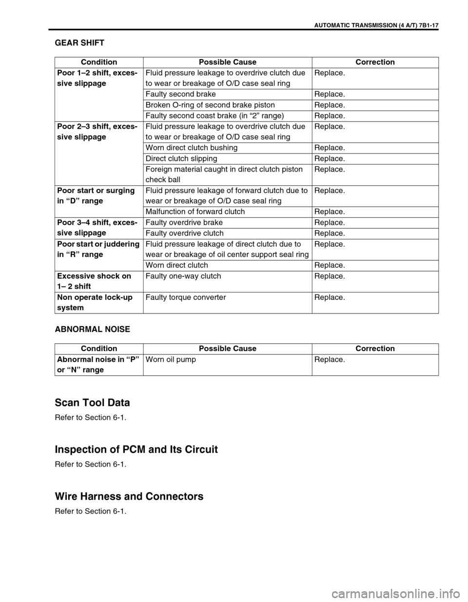
GEAR SHIFT
ABNORMAL NOISE
Scan Tool Data
Refer to Section 6-1.
Inspection of PCM and Its Circuit
Refer to Section 6-1.
Wire Harness and Connectors
Refer to Section 6-1.Condition Possible Cause Correction
Poor 1–2 shift, exces-
sive slippageFluid pressure leakage to overdrive clutch due
to wear or breakage of O/D case seal ringReplace.
Faulty second brake Replace.
Broken O-ring of second brake piston Replace.
Faulty second coast brake (in “2” range) Replace.
Poor 2–3 shift, exces-
sive slippageFluid pressure leakage to overdrive clutch due
to wear or breakage of O/D case seal ringReplace.
Worn direct clutch bushing Replace.
Direct clutch slipping Replace.
Foreign material caught in direct clutch piston
check ballReplace.
Poor start or surging
in “D” rangeFluid pressure leakage of forward clutch due to
wear or breakage of O/D case seal ringReplace.
Malfunction of forward clutch Replace.
Poor 3–4 shift, exces-
sive slippageFaulty overdrive brake Replace.
Faulty overdrive clutch Replace.
Poor start or juddering
in “R” rangeFluid pressure leakage of direct clutch due to
wear or breakage of oil center support seal ringReplace.
Worn direct clutch Replace.
Excessive shock on
1– 2 shiftFaulty one-way clutch Replace.
Non operate lock-up
systemFaulty torque converter Replace.
Condition Possible Cause Correction
Abnormal noise in “P”
or “N” rangeWorn oil pump Replace.
Page 449 of 656
7B1-40 AUTOMATIC TRANSMISSION (4 A/T)
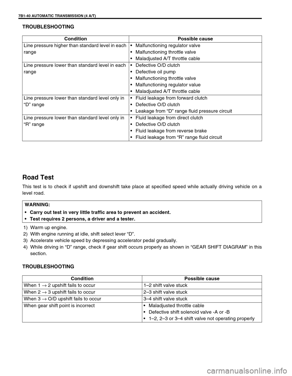
TROUBLESHOOTING
Road Test
This test is to check if upshift and downshift take place at specified speed while actually driving vehicle on a
level road.
1) Warm up engine.
2) With engine running at idle, shift select lever “D”.
3) Accelerate vehicle speed by depressing accelerator pedal gradually.
4) While driving in “D” range, check if gear shift occurs properly as shown in “GEAR SHIFT DIAGRAM” in this
section.
TROUBLESHOOTING
Condition Possible cause
Line pressure higher than standard level in each
range•Malfunctioning regulator valve
•Malfunctioning throttle valve
•Maladjusted A/T throttle cable
Line pressure lower than standard level in each
range•Defective O/D clutch
•Defective oil pump
•Malfunctioning throttle valve
•Malfunctioning regulator value
•Maladjusted A/T throttle cable
Line pressure lower than standard level only in
“D” range•Fluid leakage from forward clutch
•Defective O/D clutch
•Leakage from “D” range fluid pressure circuit
Line pressure lower than standard level only in
“R” range•Fluid leakage from direct clutch
•Defective O/D clutch
•Fluid leakage from reverse brake
•Fluid leakage from “R” range fluid circuit
WARNING:
Carry out test in very little traffic area to prevent an accident.
Test requires 2 persons, a driver and a tester.
Condition Possible cause
When 1 → 2 upshift fails to occur 1–2 shift valve stuck
When 2 → 3 upshift fails to occur 2–3 shift valve stuck
When 3 → O/D upshift fails to occur 3–4 shift valve stuck
When gear shift point is incorrect•Maladjusted throttle cable
•Defective shift solenoid valve -A or -B
•1–2, 2–3 or 3–4 shift valve not operating properly
Page 476 of 656
DIFFERENTIAL (FRONT) 7E-3
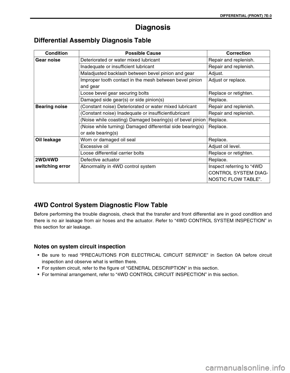
Diagnosis
Differential Assembly Diagnosis Table
4WD Control System Diagnostic Flow Table
Before performing the trouble diagnosis, check that the transfer and front differential are in good condition and
there is no air leakage from air hoses and the actuator. Refer to “4WD CONTROL SYSTEM INSPECTION” in
this section for air leakage.
Notes on system circuit inspection
•Be sure to read “PRECAUTIONS FOR ELECTRICAL CIRCUIT SERVICE” in Section 0A before circuit
inspection and observe what is written there.
•For system circuit, refer to the figure of “GENERAL DESCRIPTION” in this section.
•For terminal arrangement, refer to “4WD CONTROL CIRCUIT INSPECTION” in this section. Condition Possible Cause Correction
Gear noiseDeteriorated or water mixed lubricant Repair and replenish.
Inadequate or insufficient lubricant Repair and replenish.
Maladjusted backlash between bevel pinion and gear Adjust.
Improper tooth contact in the mesh between bevel pinion
and gearAdjust or replace.
Loose bevel gear securing bolts Replace or retighten.
Damaged side gear(s) or side pinion(s) Replace.
Bearing noise(Constant noise) Deteriorated or water mixed lubricant Repair and replenish.
(Constant noise) Inadequate or insufficientlubricant Repair and replenish.
(Noise while coasting) Damaged bearing(s) of bevel pinion Replace.
(Noise while turning) Damaged differential side bearing(s)
or axle bearing(s)Replace.
Oil leakageWorn or damaged oil seal Replace.
Excessive oil Adjust oil level.
Loose differential carrier bolts Replace or retighten.
2WD/4WD
switching errorDefective actuator Replace.
Abnormality in 4WD control system Inspect referring to “4WD
CONTROL SYSTEM DIAG-
NOSTIC FLOW TABLE”.
Page 483 of 656
7E-10 DIFFERENTIAL (FRONT)
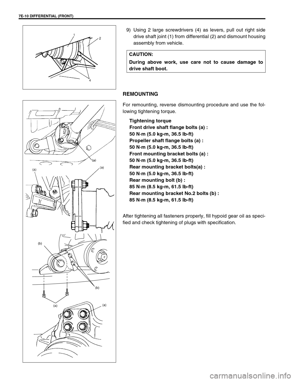
9) Using 2 large screwdrivers (4) as levers, pull out right side
drive shaft joint (1) from differential (2) and dismount housing
assembly from vehicle.
REMOUNTING
For remounting, reverse dismounting procedure and use the fol-
lowing tightening torque.
Tightening torque
Front drive shaft flange bolts (a) :
50 N·m (5.0 kg-m, 36.5 lb-ft)
Propeller shaft flange bolts (a) :
50 N·m (5.0 kg-m, 36.5 lb-ft)
Front mounting bracket bolts (a) :
50 N·m (5.0 kg-m, 36.5 lb-ft)
Rear mounting bracket bolts(a) :
50 N·m (5.0 kg-m, 36.5 lb-ft)
Rear mounting bolt (b) :
85 N·m (8.5 kg-m, 61.5 lb-ft)
Rear mounting bracket No.2 bolts (b) :
85 N·m (8.5 kg-m, 61.5 lb-ft)
After tightening all fasteners properly, fill hypoid gear oil as speci-
fied and check tightening of plugs with specification.CAUTION:
During above work, use care not to cause damage to
drive shaft boot.
(b) (b)
(a)
Page 486 of 656
DIFFERENTIAL (REAR) 7F-1
7F
SECTION 7F
DIFFERENTIAL (REAR)
CONTENTS
General Description ........................................ 7F-2
Diagnosis ......................................................... 7F-2
Diagnosis Table ............................................ 7F-2
On-Vehicle Service.......................................... 7F-3
Precaution for Maintenance Service ............. 7F-4
Differential Gear Oil Change ......................... 7F-4
Rear Differential Assembly ............................ 7F-5
Dismounting .............................................. 7F-5
Remounting ............................................... 7F-5
Unit Repair ....................................................... 7F-6Disassembling Unit ....................................... 7F-6
Component Inspection .................................. 7F-9
Sub-Assembly Adjustment and Reassembly 7F-9
Differential carrier .................................... 7F-10
Differential case ...................................... 7F-10
Differential side bearing .......................... 7F-12
Drive bevel pinion.................................... 7F-13
Assembling Unit .......................................... 7F-17
Tightening Torque Specification ................. 7F-20
Required Service Material ............................ 7F-20
Special Tool ................................................... 7F-21
Page 487 of 656
7F-2 DIFFERENTIAL (REAR)
General Description
The differential assembly using a hypoid bevel pinion and gear is installed to the rear axle. It is set in the conven-
tional type axle housing.
The differential assembly is decisive in that the drive power is concentrated there. Therefore, use of genuine
parts and specified torque is compulsory. Further, because of sliding tooth meshing with high pressure between
bevel pinion and gear, it is mandatory to lubricate them by hypoid gear oil.
Diagnosis
Diagnosis Table
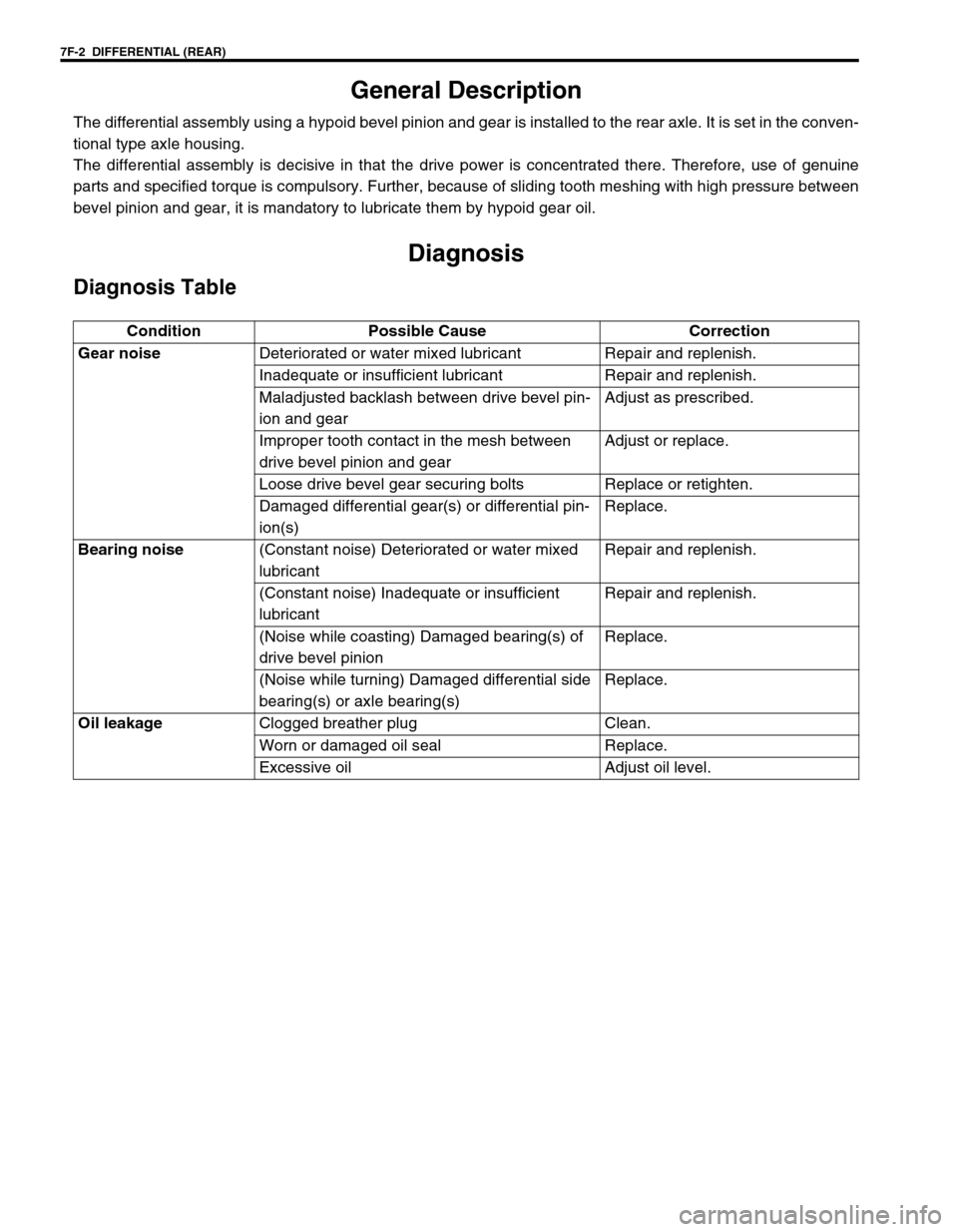
Condition Possible Cause Correction
Gear noiseDeteriorated or water mixed lubricant Repair and replenish.
Inadequate or insufficient lubricant Repair and replenish.
Maladjusted backlash between drive bevel pin-
ion and gearAdjust as prescribed.
Improper tooth contact in the mesh between
drive bevel pinion and gearAdjust or replace.
Loose drive bevel gear securing bolts Replace or retighten.
Damaged differential gear(s) or differential pin-
ion(s)Replace.
Bearing noise(Constant noise) Deteriorated or water mixed
lubricantRepair and replenish.
(Constant noise) Inadequate or insufficient
lubricantRepair and replenish.
(Noise while coasting) Damaged bearing(s) of
drive bevel pinionReplace.
(Noise while turning) Damaged differential side
bearing(s) or axle bearing(s)Replace.
Oil leakageClogged breather plug Clean.
Worn or damaged oil seal Replace.
Excessive oil Adjust oil level.