1999 SUZUKI GRAND VITARA fuse
[x] Cancel search: fusePage 595 of 656
10B-18 AIR BAG SYSTEM
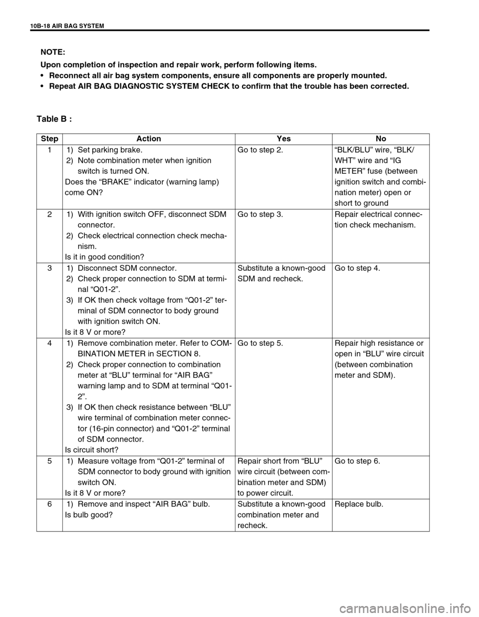
Table B :
NOTE:
Upon completion of inspection and repair work, perform following items.
Reconnect all air bag system components, ensure all components are properly mounted.
Repeat AIR BAG DIAGNOSTIC SYSTEM CHECK to confirm that the trouble has been corrected.
Step Action Yes No
1 1) Set parking brake.
2) Note combination meter when ignition
switch is turned ON.
Does the “BRAKE” indicator (warning lamp)
come ON?Go to step 2.“BLK/BLU” wire, “BLK/
WHT” wire and “IG
METER” fuse (between
ignition switch and combi-
nation meter) open or
short to ground
2 1) With ignition switch OFF, disconnect SDM
connector.
2) Check electrical connection check mecha-
nism.
Is it in good condition?Go to step 3. Repair electrical connec-
tion check mechanism.
3 1) Disconnect SDM connector.
2) Check proper connection to SDM at termi-
nal “Q01-2”.
3) If OK then check voltage from “Q01-2” ter-
minal of SDM connector to body ground
with ignition switch ON.
Is it 8 V or more?Substitute a known-good
SDM and recheck.Go to step 4.
4 1) Remove combination meter. Refer to COM-
BINATION METER in SECTION 8.
2) Check proper connection to combination
meter at “BLU” terminal for “AIR BAG”
warning lamp and to SDM at terminal “Q01-
2”.
3) If OK then check resistance between “BLU”
wire terminal of combination meter connec-
tor (16-pin connector) and “Q01-2” terminal
of SDM connector.
Is circuit short?Go to step 5. Repair high resistance or
open in “BLU” wire circuit
(between combination
meter and SDM).
5 1) Measure voltage from “Q01-2” terminal of
SDM connector to body ground with ignition
switch ON.
Is it 8 V or more?Repair short from “BLU”
wire circuit (between com-
bination meter and SDM)
to power circuit.Go to step 6.
6 1) Remove and inspect “AIR BAG” bulb.
Is bulb good?Substitute a known-good
combination meter and
recheck.Replace bulb.
Page 598 of 656
AIR BAG SYSTEM 10B-21
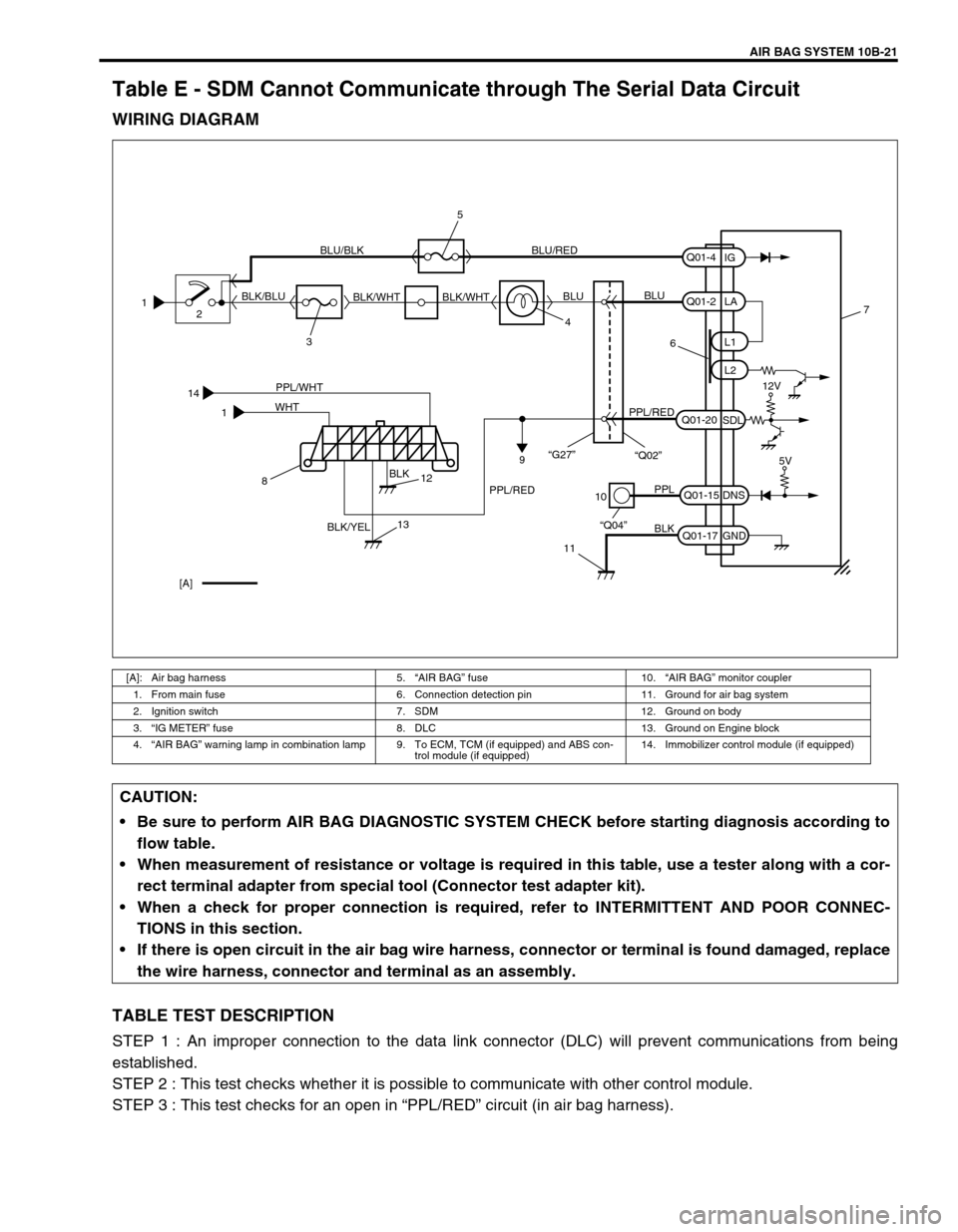
Table E - SDM Cannot Communicate through The Serial Data Circuit
WIRING DIAGRAM
TABLE TEST DESCRIPTION
STEP 1 : An improper connection to the data link connector (DLC) will prevent communications from being
established.
STEP 2 : This test checks whether it is possible to communicate with other control module.
STEP 3 : This test checks for an open in “PPL/RED” circuit (in air bag harness).
[A]: Air bag harness 5.“AIR BAG” fuse 10.“AIR BAG” monitor coupler
1. From main fuse 6. Connection detection pin 11. Ground for air bag system
2. Ignition switch 7. SDM 12. Ground on body
3.“IG METER” fuse 8. DLC 13. Ground on Engine block
4.“AIR BAG” warning lamp in combination lamp 9. To ECM, TCM (if equipped) and ABS con-
trol module (if equipped)14. Immobilizer control module (if equipped)
14
1PPL/WHT
BLK
BLK/YEL WHT
10
11
PPL
BLK
“Q04”Q01-15
Q01-17DNS
GND7
[A]5V
812
13
1
2
34 BLK/BLUBLU/BLK BLU/RED
BLK/WHT BLK/WHTBLUBLU
6
PPL/REDPPL/RED
9
Q01-2
Q01-20L1
L2
SDLLA
Q01-4
IG
12V
“G27”
“Q02”
5
CAUTION:
Be sure to perform AIR BAG DIAGNOSTIC SYSTEM CHECK before starting diagnosis according to
flow table.
When measurement of resistance or voltage is required in this table, use a tester along with a cor-
rect terminal adapter from special tool (Connector test adapter kit).
When a check for proper connection is required, refer to INTERMITTENT AND POOR CONNEC-
TIONS in this section.
If there is open circuit in the air bag wire harness, connector or terminal is found damaged, replace
the wire harness, connector and terminal as an assembly.
Page 600 of 656
AIR BAG SYSTEM 10B-23
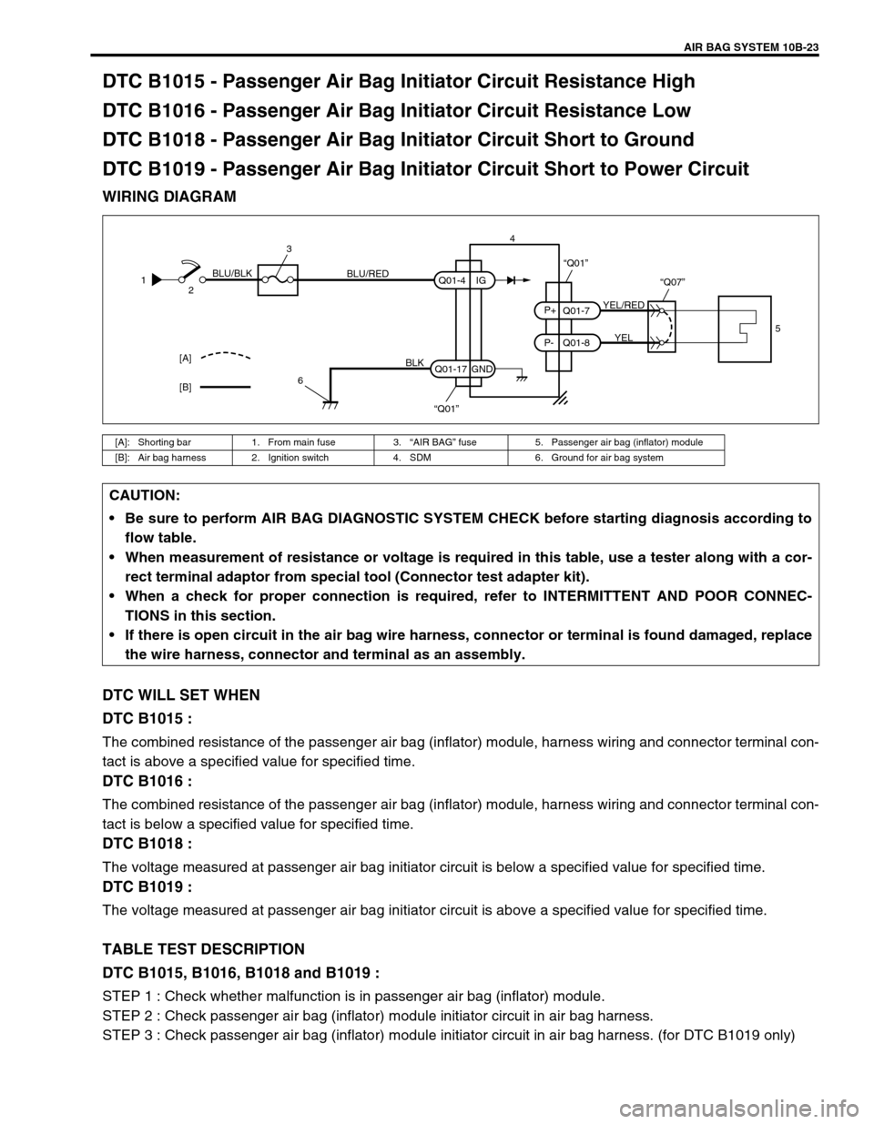
DTC B1015 - Passenger Air Bag Initiator Circuit Resistance High
DTC B1016 - Passenger Air Bag Initiator Circuit Resistance Low
DTC B1018 - Passenger Air Bag Initiator Circuit Short to Ground
DTC B1019 - Passenger Air Bag Initiator Circuit Short to Power Circuit
WIRING DIAGRAM
DTC WILL SET WHEN
DTC B1015 :
The combined resistance of the passenger air bag (inflator) module, harness wiring and connector terminal con-
tact is above a specified value for specified time.
DTC B1016 :
The combined resistance of the passenger air bag (inflator) module, harness wiring and connector terminal con-
tact is below a specified value for specified time.
DTC B1018 :
The voltage measured at passenger air bag initiator circuit is below a specified value for specified time.
DTC B1019 :
The voltage measured at passenger air bag initiator circuit is above a specified value for specified time.
TABLE TEST DESCRIPTION
DTC B1015, B1016, B1018 and B1019 :
STEP 1 : Check whether malfunction is in passenger air bag (inflator) module.
STEP 2 : Check passenger air bag (inflator) module initiator circuit in air bag harness.
STEP 3 : Check passenger air bag (inflator) module initiator circuit in air bag harness. (for DTC B1019 only)
[A]: Shorting bar 1. From main fuse 3.“AIR BAG” fuse 5. Passenger air bag (inflator) module
[B]: Air bag harness 2. Ignition switch 4. SDM 6. Ground for air bag system
1
2BLU/BLK
BLU/RED
3
6
BLK
“Q01” Q01-4
Q01-17IG
GND4
YEL/RED
YEL Q01-7
Q01-8 P- P+“Q07”
“Q01”
5
[A]
[B]
CAUTION:
Be sure to perform AIR BAG DIAGNOSTIC SYSTEM CHECK before starting diagnosis according to
flow table.
When measurement of resistance or voltage is required in this table, use a tester along with a cor-
rect terminal adaptor from special tool (Connector test adapter kit).
When a check for proper connection is required, refer to INTERMITTENT AND POOR CONNEC-
TIONS in this section.
If there is open circuit in the air bag wire harness, connector or terminal is found damaged, replace
the wire harness, connector and terminal as an assembly.
Page 605 of 656
10B-28 AIR BAG SYSTEM
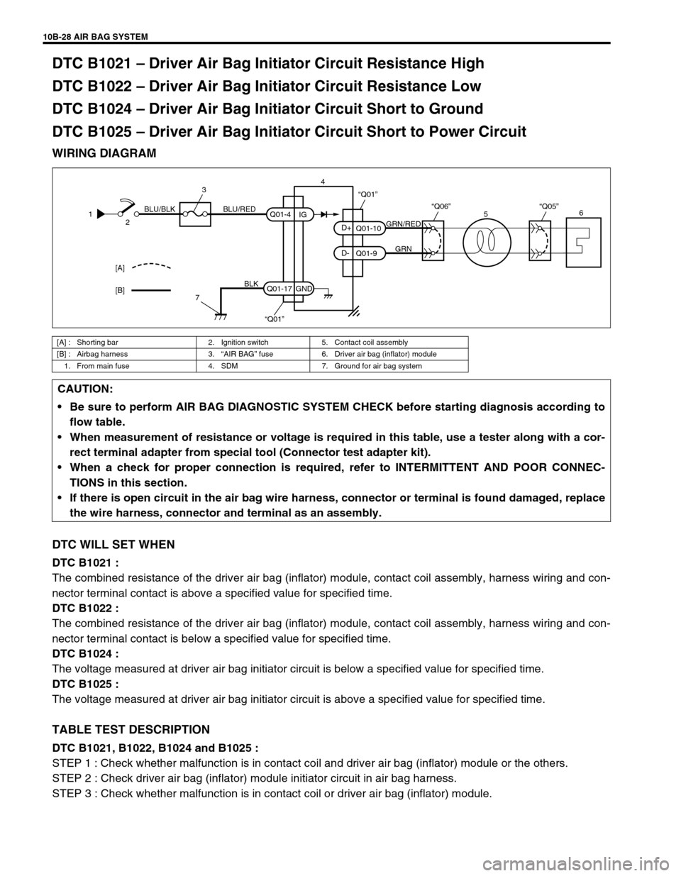
DTC B1021 – Driver Air Bag Initiator Circuit Resistance High
DTC B1022 – Driver Air Bag Initiator Circuit Resistance Low
DTC B1024 – Driver Air Bag Initiator Circuit Short to Ground
DTC B1025 – Driver Air Bag Initiator Circuit Short to Power Circuit
WIRING DIAGRAM
DTC WILL SET WHEN
DTC B1021 :
The combined resistance of the driver air bag (inflator) module, contact coil assembly, harness wiring and con-
nector terminal contact is above a specified value for specified time.
DTC B1022 :
The combined resistance of the driver air bag (inflator) module, contact coil assembly, harness wiring and con-
nector terminal contact is below a specified value for specified time.
DTC B1024 :
The voltage measured at driver air bag initiator circuit is below a specified value for specified time.
DTC B1025 :
The voltage measured at driver air bag initiator circuit is above a specified value for specified time.
TABLE TEST DESCRIPTION
DTC B1021, B1022, B1024 and B1025 :
STEP 1 : Check whether malfunction is in contact coil and driver air bag (inflator) module or the others.
STEP 2 : Check driver air bag (inflator) module initiator circuit in air bag harness.
STEP 3 : Check whether malfunction is in contact coil or driver air bag (inflator) module.
[A] : Shorting bar 2. Ignition switch 5. Contact coil assembly
[B] : Airbag harness 3.“AIR BAG” fuse 6. Driver air bag (inflator) module
1. From main fuse 4. SDM 7. Ground for air bag system
1
2BLU/RED BLU/BLK
3
7
BLK
“Q01” Q01-4
Q01-17IG
GND4
[A]
[B]
GRN/RED
GRN Q01-10
Q01-9 D- D+“Q06”
“Q01”
“Q05”6
5
CAUTION:
Be sure to perform AIR BAG DIAGNOSTIC SYSTEM CHECK before starting diagnosis according to
flow table.
When measurement of resistance or voltage is required in this table, use a tester along with a cor-
rect terminal adapter from special tool (Connector test adapter kit).
When a check for proper connection is required, refer to INTERMITTENT AND POOR CONNEC-
TIONS in this section.
If there is open circuit in the air bag wire harness, connector or terminal is found damaged, replace
the wire harness, connector and terminal as an assembly.
Page 610 of 656
AIR BAG SYSTEM 10B-33
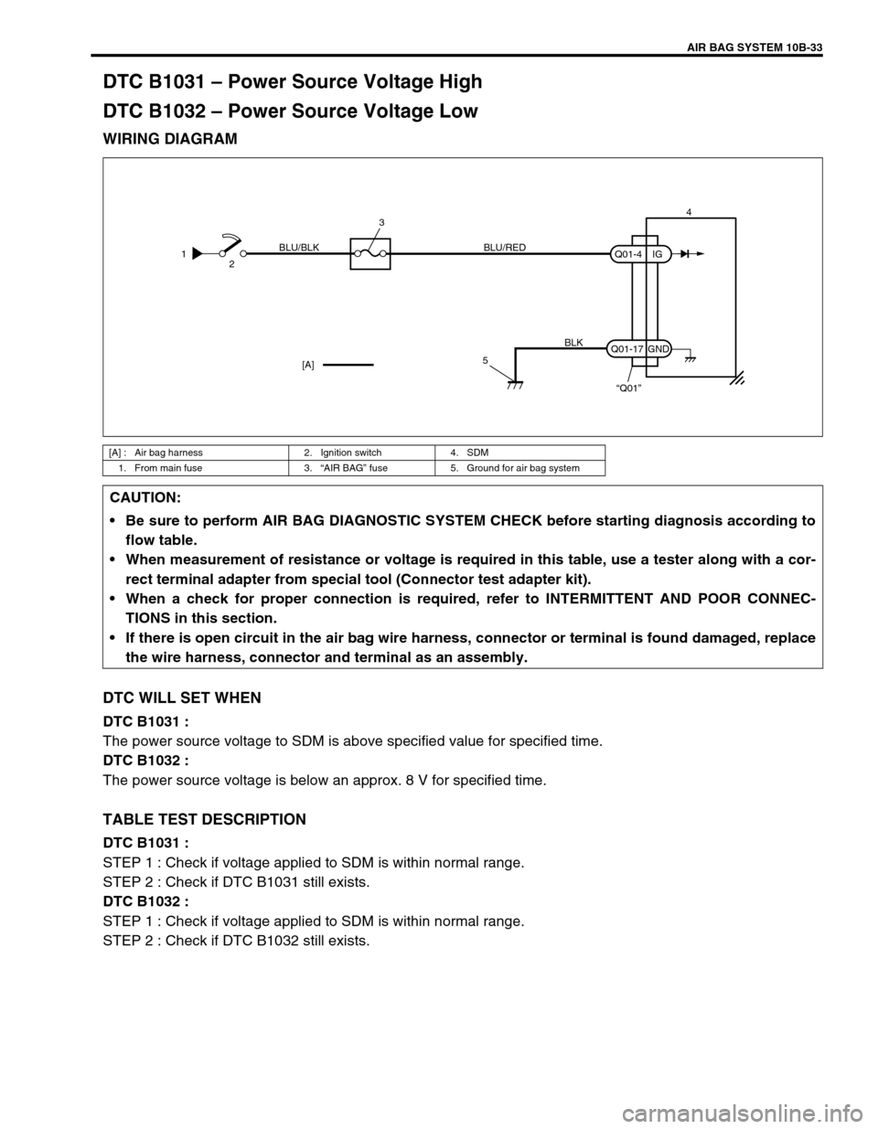
DTC B1031 – Power Source Voltage High
DTC B1032 – Power Source Voltage Low
WIRING DIAGRAM
DTC WILL SET WHEN
DTC B1031 :
The power source voltage to SDM is above specified value for specified time.
DTC B1032 :
The power source voltage is below an approx. 8 V for specified time.
TABLE TEST DESCRIPTION
DTC B1031 :
STEP 1 : Check if voltage applied to SDM is within normal range.
STEP 2 : Check if DTC B1031 still exists.
DTC B1032 :
STEP 1 : Check if voltage applied to SDM is within normal range.
STEP 2 : Check if DTC B1032 still exists.
[A] : Air bag harness 2. Ignition switch 4. SDM
1. From main fuse 3.“AIR BAG” fuse 5. Ground for air bag system
1
2BLU/RED BLU/BLK
3
5
BLK
“Q01” Q01-4
Q01-17IG
GND4
[A]
CAUTION:
Be sure to perform AIR BAG DIAGNOSTIC SYSTEM CHECK before starting diagnosis according to
flow table.
When measurement of resistance or voltage is required in this table, use a tester along with a cor-
rect terminal adapter from special tool (Connector test adapter kit).
When a check for proper connection is required, refer to INTERMITTENT AND POOR CONNEC-
TIONS in this section.
If there is open circuit in the air bag wire harness, connector or terminal is found damaged, replace
the wire harness, connector and terminal as an assembly.
Page 617 of 656
10B-40 AIR BAG SYSTEM
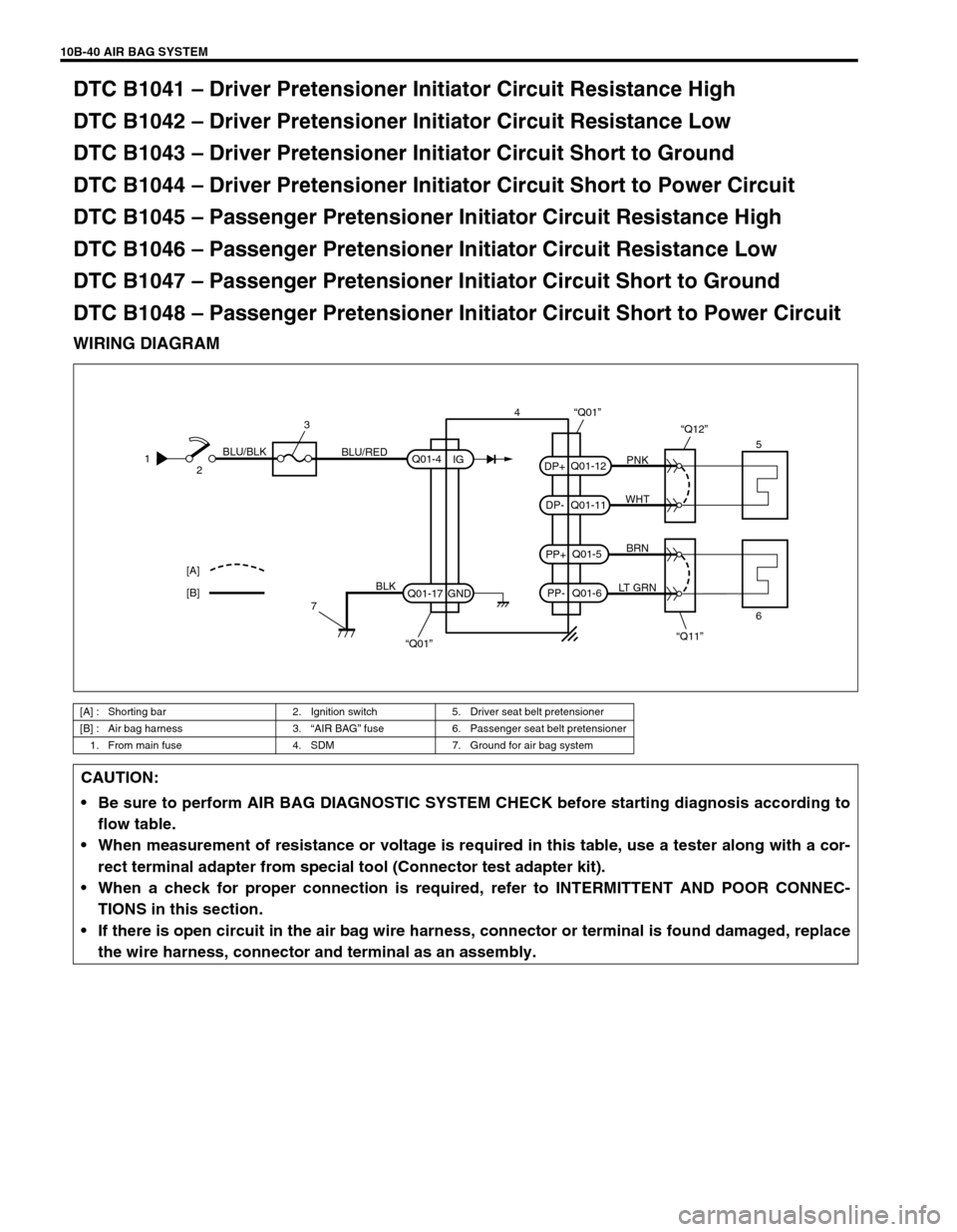
DTC B1041 – Driver Pretensioner Initiator Circuit Resistance High
DTC B1042 – Driver Pretensioner Initiator Circuit Resistance Low
DTC B1043 – Driver Pretensioner Initiator Circuit Short to Ground
DTC B1044 – Driver Pretensioner Initiator Circuit Short to Power Circuit
DTC B1045 – Passenger Pretensioner Initiator Circuit Resistance High
DTC B1046 – Passenger Pretensioner Initiator Circuit Resistance Low
DTC B1047 – Passenger Pretensioner Initiator Circuit Short to Ground
DTC B1048 – Passenger Pretensioner Initiator Circuit Short to Power Circuit
WIRING DIAGRAM
[A] : Shorting bar 2. Ignition switch 5. Driver seat belt pretensioner
[B] : Air bag harness 3.“AIR BAG” fuse 6. Passenger seat belt pretensioner
1. From main fuse 4. SDM 7. Ground for air bag system
PNK
WHT
BRN
LT GRN
“Q11” “Q12”
Q01-12
Q01-11
Q01-5
Q01-6 PP- PP+ DP- DP+
“Q01”
5
6 [A]
[B]1
2BLU/BLK
BLU/RED
3
7
BLK
“Q01” Q01-4
Q01-17IG
GND4
CAUTION:
Be sure to perform AIR BAG DIAGNOSTIC SYSTEM CHECK before starting diagnosis according to
flow table.
When measurement of resistance or voltage is required in this table, use a tester along with a cor-
rect terminal adapter from special tool (Connector test adapter kit).
When a check for proper connection is required, refer to INTERMITTENT AND POOR CONNEC-
TIONS in this section.
If there is open circuit in the air bag wire harness, connector or terminal is found damaged, replace
the wire harness, connector and terminal as an assembly.
Page 624 of 656
AIR BAG SYSTEM 10B-47
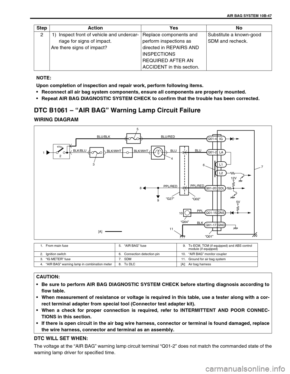
DTC B1061 – “AIR BAG” Warning Lamp Circuit Failure
WIRING DIAGRAM
DTC WILL SET WHEN:
The voltage at the “AIR BAG” warning lamp circuit terminal “Q01-2” does not match the commanded state of the
warning lamp driver for specified time.2 1) Inspect front of vehicle and undercar-
riage for signs of impact.
Are there signs of impact?Replace components and
perform inspections as
directed in REPAIRS AND
INSPECTIONS
REQUIRED AFTER AN
ACCIDENT in this section.Substitute a known-good
SDM and recheck. Step Action Yes No
NOTE:
Upon completion of inspection and repair work, perform following items.
Reconnect all air bag system components, ensure all components are properly mounted.
Repeat AIR BAG DIAGNOSTIC SYSTEM CHECK to confirm that the trouble has been corrected.
1. From main fuse 5.“AIR BAG” fuse 9. To ECM, TCM (if equipped) and ABS control
module (if equipped)
2. Ignition switch 6. Connection detection pin 10.“AIR BAG” monitor coupler
3.“IG METER” fuse 7. SDM 11. Ground for air bag system
4.“AIR BAG” warning lamp in combination meter 8. To DLC [A]: Air bag harness
1
2
34 BLK/BLUBLU/BLK BLU/RED
BLK/WHT BLK/WHTBLUBLU
6
PPL/REDPPL/RED
8
9
10
11
PPL
BLK
“Q04”
“Q01”
Q01-2
Q01-20
Q01-15
Q01-17L1
L2
SDL
DNS
GNDLA
Q01-4
IG
7
[A]
12V
5V
“G27”“Q02”
5
CAUTION:
Be sure to perform AIR BAG DIAGNOSTIC SYSTEM CHECK before starting diagnosis according to
flow table.
When measurement of resistance or voltage is required in this table, use a tester along with a cor-
rect terminal adapter from special tool (Connector test adapter kit).
When a check for proper connection is required, refer to INTERMITTENT AND POOR CONNEC-
TIONS in this section.
If there is open circuit in the air bag wire harness, connector or terminal is found damaged, replace
the wire harness, connector and terminal as an assembly.
Page 626 of 656
AIR BAG SYSTEM 10B-49
On-Vehicle Service
Service Precautions
Service and diagnosis
WARNING/CAUTION labels are attached on each part of air bag system components (SDM, air bag (inflator)
modules and seat belt pretensioners). Be sure to follow the instructions.
•Many of service procedures require disconnection of “AIR BAG” fuse and air bag (inflator) module(s) (driver
and passenger) from initiator circuit to avoid an accidental deployment.
•Do not apply power to the air bag system unless all components are connected or a diagnostic chart
requests it, as this will set a diagnostic trouble code (DTC).
•The “AIR BAG DIAGNOSTIC SYSTEM CHECK” must be the starting point of any air bag diagnostics. The
“AIR BAG DIAGNOSTIC SYSTEM CHECK” will verify proper “AIR BAG” warning lamp operation and will
lead you to the correct table to diagnose any air bag malfunctions. Bypassing these procedures may result in
extended diagnostic time, incorrect diagnosis, and incorrect parts replacements.
•Never use air bag component parts from another vehicle.
•If the vehicle will be exposed to temperatures over 93°C (200°F) (for example, during a paint baking pro-
cess), remove the air bag system components beforehand to avoid component damage or unintended sys-
tem activation.
•When handling the air bag (inflator) modules (driver and passenger), seat belt pretensioners (driver and
passenger) or SDM, be careful not to drop it or apply an impact to it. If an excessive impact was applied
(e.g., SDM is dropped, air bag (inflator) module is dropped from a height of 90 cm (3 ft) or more, seat belt
pretensioner (retractor assembly) is dropped from a height of 30 cm (1 ft) or more), never attempt disassem-
bly or repair but replace it with a new one.
•When using electric welding, be sure to disconnect air bag (inflator) module connectors (driver and passen-
ger) and seat belt pretensioner connectors (driver and passenger) respectively.
•When applying paint around the air bag system related parts, use care so that the harness or connector will
not be exposed to the paint mist.
•Never expose air bag system component parts directly to hot air (drying or baking the vehicle after painting)
or flames. WARNING:
If the air bag system and another vehicle system both need repair, Suzuki recommends that the air
bag system be repaired first, to help avoid unintended air bag system activation.
Do not modify the steering wheel, dashboard or any other on or around air bag system compo-
nents. Modifications can adversely affect air bag system performance and lead to injury.
Failure to follow procedures could result in possible air bag system activation, personal injury or
unneeded air bag system repairs.
WARNING:
When performing service on or around air bag system components or air bag wiring, follow the proce-
dures listed in the following pages to temporarily disable the air bag system.
Failure to follow procedures could result in possible air bag system activation, personal injury or
unneeded air bag system repairs.