Page 205 of 1456

TROUBLE PROBLEM PARTS, ETC. POSSIBLE CAUSE RANK
5. Engine does not return
to idle.IFuel injection system A
IIntake systemILoosened or cracked vacuum hose A
IOthersIStuck or damaged throttle valve A
IAccelerator cable out of adjustment B
6. Dieseling (Run-on)IFuel injection system A
ICooling systemIOverheating B
IOthersIAccelerator cable out of adjustment B
7. After burning in exhaust
systemIFuel injection system A
IIntake systemILoosened or cracked intake duct C
ILoosened or cracked PCV hose C
ILoosened or cracked vacuum hose B
IDefective PCV valve B
ILoosened oil filler cap C
IBeltIDefective timing B
ICompressionIIncorrect valve clearance B
ILoosened spark plugs or defective gasket C
ILoosened cylinder head bolts or defective gasket C
IImproper valve seating B
IDefective valve stem C
IWorn or broken valve spring C
IWorn or stuck piston rings, cylinder and piston C
IIncorrect valve timing A
ILubrication systemIIncorrect oil pressure C
ICooling systemIOver cooling C
IOthersIMalfunction of evaporative emission control system C
8. KnockingIFuel injection system A
IIntake systemILoosened oil filler cap B
IBeltIDefective timing B
ICompressionIIncorrect valve clearance C
IIncorrect valve timing B
ICooling systemIOverheating A
9. Excessive engine oil
consumptionIIntake systemILoosened or cracked PCV hose A
IDefective PCV valve B
ILoosened oil filler cap C
ICompressionIDefective valve stem A
IWorn or stuck piston rings, cylinder and piston A
ILubrication systemILoosened oil pump attaching bolts and defective gasket B
IDefective oil filter seal B
IDefective crankshaft oil seal B
IDefective rocker cover gasket B
ILoosened oil drain plug or defective gasket B
ILoosened oil pan fitting bolts or defective oil pan B
74
2-3b[K100]DIAGNOSTICS
1. Engine Trouble in General
Page 207 of 1456
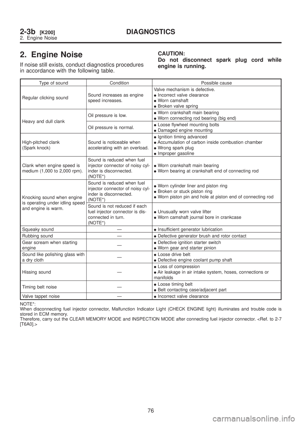
2. Engine Noise
If noise still exists, conduct diagnostics procedures
in accordance with the following table.CAUTION:
Do not disconnect spark plug cord while
engine is running.
Type of sound Condition Possible cause
Regular clicking soundSound increases as engine
speed increases.Valve mechanism is defective.
IIncorrect valve clearance
IWorn camshaft
IBroken valve spring
Heavy and dull clankOil pressure is low.IWorn crankshaft main bearing
IWorn connecting rod bearing (big end)
Oil pressure is normal.ILoose flywheel mounting bolts
IDamaged engine mounting
High-pitched clank
(Spark knock)Sound is noticeable when
accelerating with an overload.IIgnition timing advanced
IAccumulation of carbon inside combustion chamber
IWrong spark plug
IImproper gasoline
Clank when engine speed is
medium (1,000 to 2,000 rpm).Sound is reduced when fuel
injector connector of noisy cyl-
inder is disconnected.
(NOTE*)IWorn crankshaft main bearing
IWorn bearing at crankshaft end of connecting rod
Knocking sound when engine
is operating under idling speed
and engine is warm.Sound is reduced when fuel
injector connector of noisy cyl-
inder is disconnected.
(NOTE*)IWorn cylinder liner and piston ring
IBroken or stuck piston ring
IWorn piston pin and hole at piston end of connecting rod
Sound is not reduced if each
fuel injector connector is dis-
connected in turn.
(NOTE*)IUnusually worn valve lifter
IWorn camshaft journal bore in crankcase
Squeaky sound ÐIInsufficient generator lubrication
Rubbing sound ÐIDefective generator brush and rotor contact
Gear scream when starting
engineÐIDefective ignition starter switch
IWorn gear and starter pinion
Sound like polishing glass with
a dry clothÐILoose drive belt
IDefective engine coolant pump shaft
Hissing sound ÐILoss of compression
IAir leakage in air intake system, hoses, connections or
manifolds
Timing belt noise ÐILoose timing belt
IBelt contacting case/adjacent part
Valve tappet noise ÐIIncorrect valve clearance
NOTE*:
When disconnecting fuel injector connector, Malfunction Indicator Light (CHECK ENGINE light) illuminates and trouble code is
stored in ECM memory.
Therefore, carry out the CLEAR MEMORY MODE and INSPECTION MODE after connecting fuel injector connector.
[T6A0].>
76
2-3b[K200]DIAGNOSTICS
2. Engine Noise
Page 208 of 1456
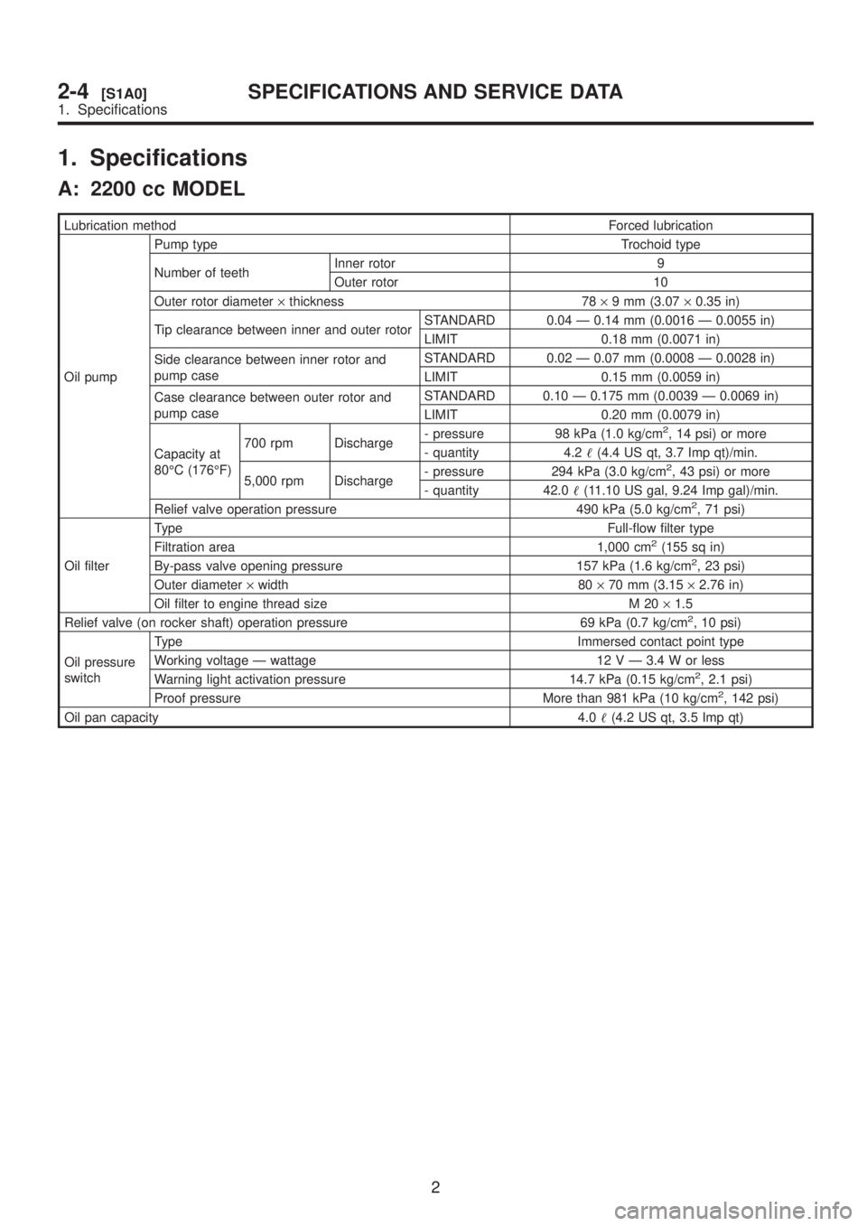
1. Specifications
A: 2200 cc MODEL
Lubrication methodForced lubrication
Oil pumpPump type Trochoid type
Number of teethInner rotor 9
Outer rotor 10
Outer rotor diameter´thickness 78´9 mm (3.07´0.35 in)
Tip clearance between inner and outer rotorSTANDARD 0.04 Ð 0.14 mm (0.0016 Ð 0.0055 in)
LIMIT 0.18 mm (0.0071 in)
Side clearance between inner rotor and
pump caseSTANDARD 0.02 Ð 0.07 mm (0.0008 Ð 0.0028 in)
LIMIT 0.15 mm (0.0059 in)
Case clearance between outer rotor and
pump caseSTANDARD 0.10 Ð 0.175 mm (0.0039 Ð 0.0069 in)
LIMIT 0.20 mm (0.0079 in)
Capacity at
80ÉC (176ÉF)700 rpm Discharge- pressure 98 kPa (1.0 kg/cm
2, 14 psi) or more
- quantity 4.2(4.4 US qt, 3.7 Imp qt)/min.
5,000 rpm Discharge- pressure 294 kPa (3.0 kg/cm
2, 43 psi) or more
- quantity 42.0(11.10 US gal, 9.24 Imp gal)/min.
Relief valve operation pressure 490 kPa (5.0 kg/cm
2, 71 psi)
Oil filterTypeFull-flow filter type
Filtration area 1,000 cm
2(155 sq in)
By-pass valve opening pressure 157 kPa (1.6 kg/cm2, 23 psi)
Outer diameter´width 80´70 mm (3.15´2.76 in)
Oil filter to engine thread size M 20´1.5
Relief valve (on rocker shaft) operation pressure 69 kPa (0.7 kg/cm
2, 10 psi)
Oil pressure
switchType Immersed contact point type
Working voltage Ð wattage 12 V Ð 3.4 W or less
Warning light activation pressure 14.7 kPa (0.15 kg/cm
2, 2.1 psi)
Proof pressure More than 981 kPa (10 kg/cm2, 142 psi)
Oil pan capacity4.0(4.2 US qt, 3.5 Imp qt)
2
2-4[S1A0]SPECIFICATIONS AND SERVICE DATA
1. Specifications
Page 209 of 1456
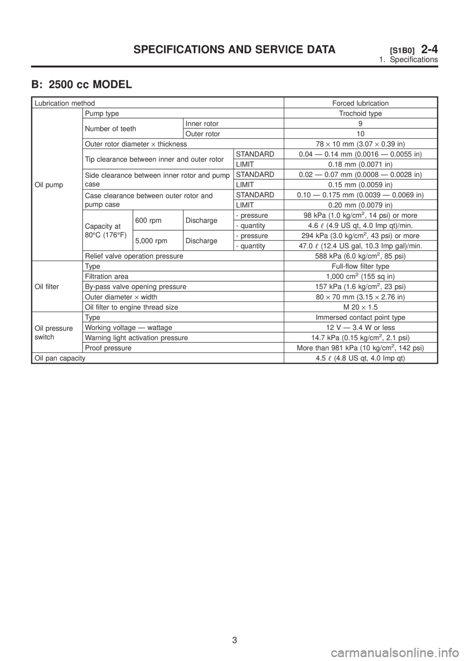
B: 2500 cc MODEL
Lubrication methodForced lubrication
Oil pumpPump type Trochoid type
Number of teethInner rotor 9
Outer rotor 10
Outer rotor diameter´thickness 78´10 mm (3.07´0.39 in)
Tip clearance between inner and outer rotorSTANDARD 0.04 Ð 0.14 mm (0.0016 Ð 0.0055 in)
LIMIT 0.18 mm (0.0071 in)
Side clearance between inner rotor and pump
caseSTANDARD 0.02 Ð 0.07 mm (0.0008 Ð 0.0028 in)
LIMIT 0.15 mm (0.0059 in)
Case clearance between outer rotor and
pump caseSTANDARD 0.10 Ð 0.175 mm (0.0039 Ð 0.0069 in)
LIMIT 0.20 mm (0.0079 in)
Capacity at
80ÉC (176ÉF)600 rpm Discharge- pressure 98 kPa (1.0 kg/cm
2, 14 psi) or more
- quantity 4.6(4.9 US qt, 4.0 Imp qt)/min.
5,000 rpm Discharge- pressure 294 kPa (3.0 kg/cm
2, 43 psi) or more
- quantity 47.0(12.4 US gal, 10.3 Imp gal)/min.
Relief valve operation pressure 588 kPa (6.0 kg/cm
2, 85 psi)
Oil filterTypeFull-flow filter type
Filtration area 1,000 cm
2(155 sq in)
By-pass valve opening pressure 157 kPa (1.6 kg/cm2, 23 psi)
Outer diameter´width 80´70 mm (3.15´2.76 in)
Oil filter to engine thread size M 20´1.5
Oil pressure
switchType Immersed contact point type
Working voltage Ð wattage 12 V Ð 3.4 W or less
Warning light activation pressure 14.7 kPa (0.15 kg/cm
2, 2.1 psi)
Proof pressure More than 981 kPa (10 kg/cm2, 142 psi)
Oil pan capacity4.5(4.8 US qt, 4.0 Imp qt)
3
[S1B0]2-4SPECIFICATIONS AND SERVICE DATA
1. Specifications
Page 210 of 1456
1. Lubrication System
A: 2200 cc MODEL
B2M2235A
(1) Plug
(2) Washer
(3) Relief valve spring
(4) Relief valve
(5) Oil seal
(6) Oil pump case
(7) Inner rotor
(8) Outer rotor
(9) Oil pump cover
(10) Oil filter
(11) O-ring
(12) Oil pump ASSY(13) Oil pressure switch
(14) Oil filler duct
(15) O-ring
(16) Oil filler cap
(17) O-ring
(18) Baffle plate
(19) O-ring
(20) Oil strainer
(21) Oil level gauge guide
(22) O-ring
(23) Oil pan
(24) Oil level gauge(25) Drain plug
(26) Metal gasket
Tightening torque: N´m (kg-m, ft-lb)
T1:
5 (0.5, 3.6)
T2:5+1/þ0(0.5+0.1/þ0, 3.6+0.7/þ0)
T3:6.4 (0.65, 4.7)
T4:9.8 (1.0, 7.0)
T5:44.1±3.4 (4.5±0.35, 32.5±2.5)
4
2-4[C1A0]COMPONENT PARTS
1. Lubrication System
Page 211 of 1456
B: 2500 cc MODEL
H2M2426A
(1) Plug
(2) Washer
(3) Relief valve spring
(4) Relief valve
(5) Oil seal
(6) Oil pump case
(7) Inner rotor
(8) Outer rotor
(9) Oil pump cover
(10) Oil filter
(11) Plug
(12) Gasket(13) Oil filter connector
(14) O-ring
(15) Oil pump ASSY
(16) Oil pressure switch
(17) Oil filler duct
(18) O-ring
(19) Cylinder head cover
(20) Baffle plate
(21) O-ring
(22) Oil strainer
(23) Gasket
(24) Oil level gauge guide(25) Oil pan
(26) Oil level gauge
(27) Metal gasket
(28) Drain plug
Tightening torque: N´m (kg-m, ft-lb)
T1:
5 (0.5, 3.6)
T2:5+1/þ0(0.5+0.1/þ0, 3.6+0.7/þ0)
T3:6.4 (0.65, 4.7)
T4:10 (1.0, 7.0)
T5:44.1±3.4 (4.5±0.35, 32.5±2.5)
5
[C1B0]2-4COMPONENT PARTS
1. Lubrication System
Page 212 of 1456
1. Oil Pump
A: REMOVAL
1) Disconnect battery ground cable.
G6M0095
2) Lift-up the vehicle.
3) Remove under cover.
B2M0014
4) Drain coolant.
B2M0015A
5) Remove radiator.
S2M0033
6) Lower the vehicle.
7) Remove crankshaft position sensor.
B2M1252A
8) Remove camshaft position sensor.
G2M0417
9) Remove V-belts.
G2M0286
10) Remove rear side V-belt tensioner.
S2M0113
6
2-4[W1A0]SERVICE PROCEDURE
1. Oil Pump
Page 213 of 1456
11) Remove crankshaft pulley by using ST.
ST 49997700 CRANKSHAFT PULLEY
WRENCH
S2M0114
12) Remove water pump.
S2M0022
13) Remove timing belt guide. (MT vehicles only)
S2M0115
14) Remove crankshaft sprocket.
S2M0116
15) Remove bolts which install oil pump onto cyl-
inder block.
S2M0117
16) Remove oil pump by using flat bladed screw-
driver.
CAUTION:
Be careful not to scratch mating surfaces of
cylinder block and oil pump.
S2M0722A
7
[W1A0]2-4SERVICE PROCEDURE
1. Oil Pump


