Page 569 of 1456

G3M0322
3. ENGINE BRAKE OPERATION
Engine brake operation:
D range
®4th gear
3 range
®3rd gear
2 range
®2nd gear
1 range
®1st gear
4. AWD FUNCTION
If ªtight-corner brakingº occurs when the steering
wheel is fully turned at low speed:
1) Determine the applicable trouble code and
check the corresponding duty solenoid C (transfer)
for improper operation.
2) If the solenoid is operating properly, check
transfer clutch pressure.
3) If oil pressure is normal but ªtight-corner brak-
ingº occurs:
Check the transfer control valve for sticking, and
the transfer clutch facing for wear.
[W20B0].> and
7. Stall Test
A: MEASUREMENT
1. GENERAL INFORMATION
The stall test is of extreme importance in diagnos-
ing the condition of the automatic transmission and
the engine. It should be conducted to measure the
engine stall speeds in R and 2 ranges.
Purposes of the stall test:
1) To check the operation of the automatic trans-
mission clutch.
2) To check the operation of the torque converter
clutch.
3) To check engine performance.
2. TEST METHODS
1) Preparations before test:
(1) Check that throttle valve opens fully.
(2) Check that engine oil level is correct.
(3) Check that coolant level is correct.
(4) Check that ATF level is correct.
(5) Check that differential gear oil level is cor-
rect.
(6) Increase ATF temperature to 50 to 80ÉC
(122 to 176ÉF) by idling the engine for approxi-
mately 30 minutes (with select lever set to ªNº
or ªPº).
2) Install an engine tachometer at a location vis-
ible from the driver's compartment and mark the
41
[W7A2]3-2SERVICE PROCEDURE
7. Stall Test
Page 636 of 1456
22. Transmission Control
Module
A: REMOVAL
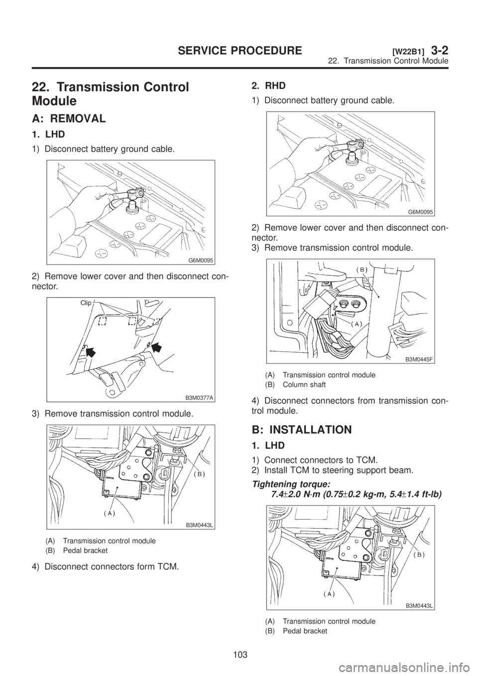
1. LHD
1) Disconnect battery ground cable.
G6M0095
2) Remove lower cover and then disconnect con-
nector.
B3M0377A
3) Remove transmission control module.
B3M0443L
(A) Transmission control module
(B) Pedal bracket
4) Disconnect connectors form TCM.
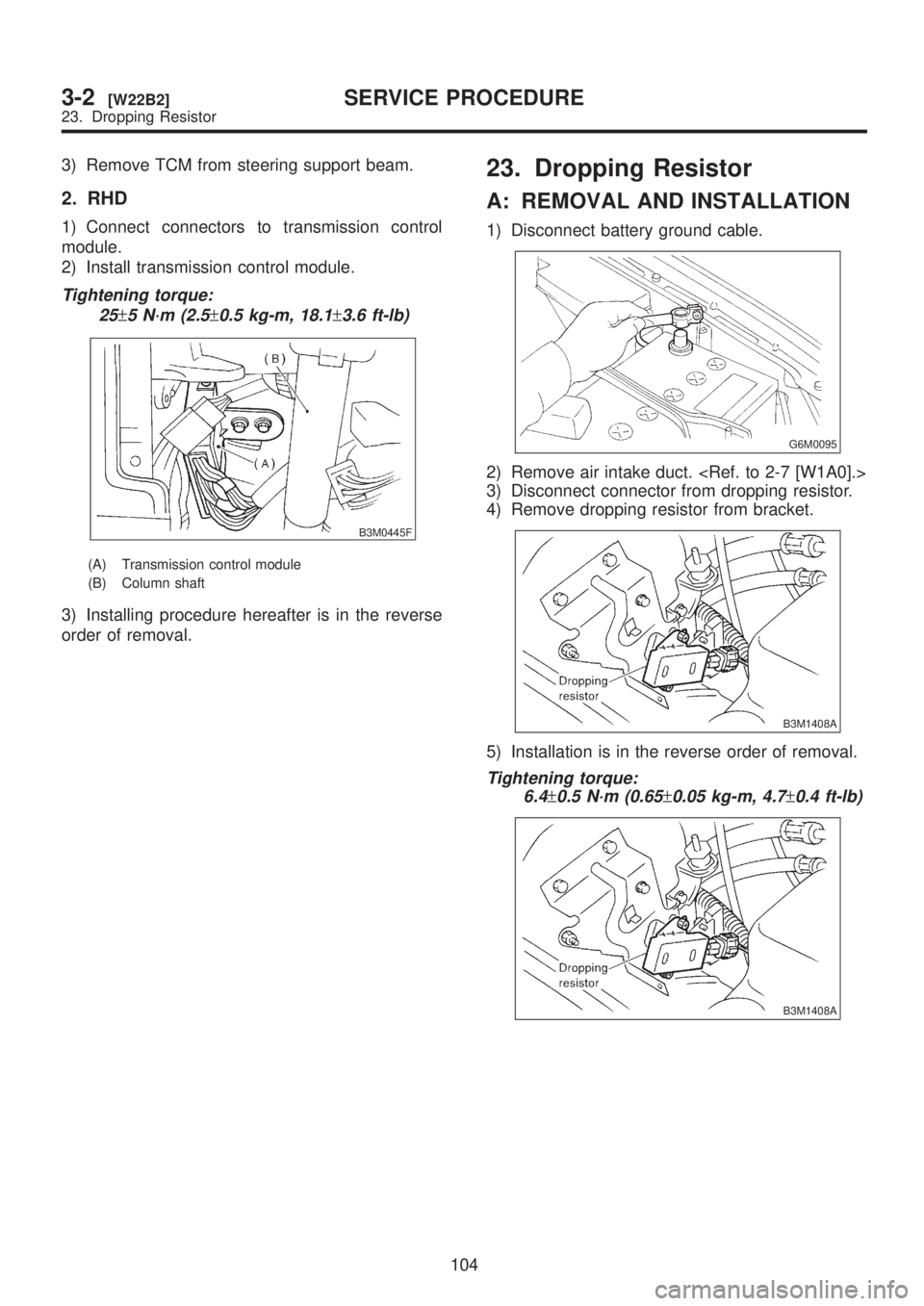
2. RHD
1) Disconnect battery ground cable.
G6M0095
2) Remove lower cover and then disconnect con-
nector.
3) Remove transmission control module.
B3M0445F
(A) Transmission control module
(B) Column shaft
4) Disconnect connectors from transmission con-
trol module.
B: INSTALLATION
1. LHD
1) Connect connectors to TCM.
2) Install TCM to steering support beam.
Tightening torque:
7.4
±2.0 N´m (0.75±0.2 kg-m, 5.4±1.4 ft-lb)
B3M0443L
(A) Transmission control module
(B) Pedal bracket
103
[W22B1]3-2SERVICE PROCEDURE
22. Transmission Control Module
Page 637 of 1456
3) Remove TCM from steering support beam.
2. RHD
1) Connect connectors to transmission control
module.
2) Install transmission control module.
Tightening torque:
25
±5 N´m (2.5±0.5 kg-m, 18.1±3.6 ft-lb)
B3M0445F
(A) Transmission control module
(B) Column shaft
3) Installing procedure hereafter is in the reverse
order of removal.
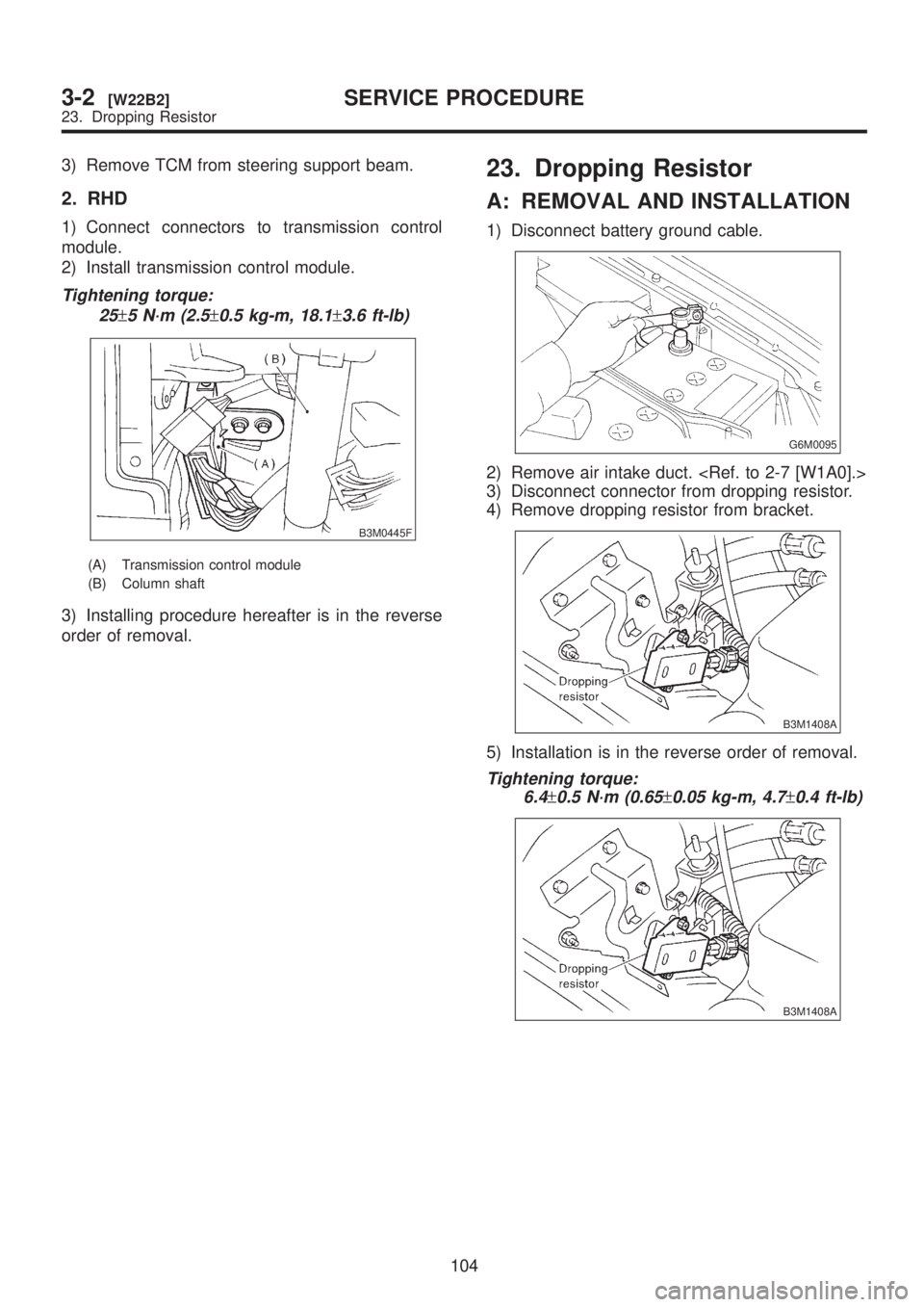
23. Dropping Resistor
A: REMOVAL AND INSTALLATION
1) Disconnect battery ground cable.
G6M0095
2) Remove air intake duct.
3) Disconnect connector from dropping resistor.
4) Remove dropping resistor from bracket.
B3M1408A
5) Installation is in the reverse order of removal.
Tightening torque:
6.4
±0.5 N´m (0.65±0.05 kg-m, 4.7±0.4 ft-lb)
B3M1408A
104
3-2[W22B2]SERVICE PROCEDURE
23. Dropping Resistor
Page 638 of 1456
3) Remove TCM from steering support beam.
2. RHD
1) Connect connectors to transmission control
module.
2) Install transmission control module.
Tightening torque:
25
±5 N´m (2.5±0.5 kg-m, 18.1±3.6 ft-lb)
B3M0445F
(A) Transmission control module
(B) Column shaft
3) Installing procedure hereafter is in the reverse
order of removal.
23. Dropping Resistor
A: REMOVAL AND INSTALLATION
1) Disconnect battery ground cable.
G6M0095
2) Remove air intake duct.
3) Disconnect connector from dropping resistor.
4) Remove dropping resistor from bracket.
B3M1408A
5) Installation is in the reverse order of removal.
Tightening torque:
6.4
±0.5 N´m (0.65±0.05 kg-m, 4.7±0.4 ft-lb)
B3M1408A
104
3-2[W22B2]SERVICE PROCEDURE
23. Dropping Resistor
Page 710 of 1456
B: INSPECTION AND ADJUSTMENT
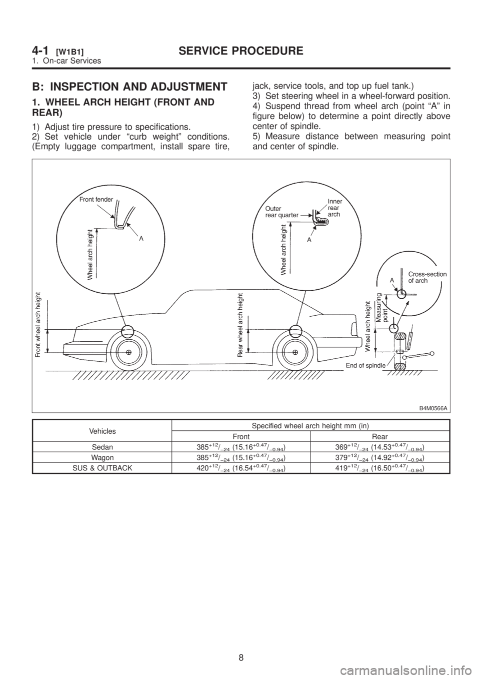
1. WHEEL ARCH HEIGHT (FRONT AND
REAR)
1) Adjust tire pressure to specifications.
2) Set vehicle under ªcurb weightº conditions.
(Empty luggage compartment, install spare tire,jack, service tools, and top up fuel tank.)
3) Set steering wheel in a wheel-forward position.
4) Suspend thread from wheel arch (point ªAº in
figure below) to determine a point directly above
center of spindle.
5) Measure distance between measuring point
and center of spindle.
B4M0566A
VehiclesSpecified wheel arch height mm (in)
Front Rear
Sedan 385
+12/þ24(15.16+0.47/þ0.94) 369+12/þ24(14.53+0.47/þ0.94)
Wagon 385+12/þ24(15.16+0.47/þ0.94) 379+12/þ24(14.92+0.47/þ0.94)
SUS & OUTBACK 420+12/þ24(16.54+0.47/þ0.94) 419+12/þ24(16.50+0.47/þ0.94)
8
4-1[W1B1]SERVICE PROCEDURE
1. On-car Services
Page 712 of 1456
3. CASTER (FRONT)
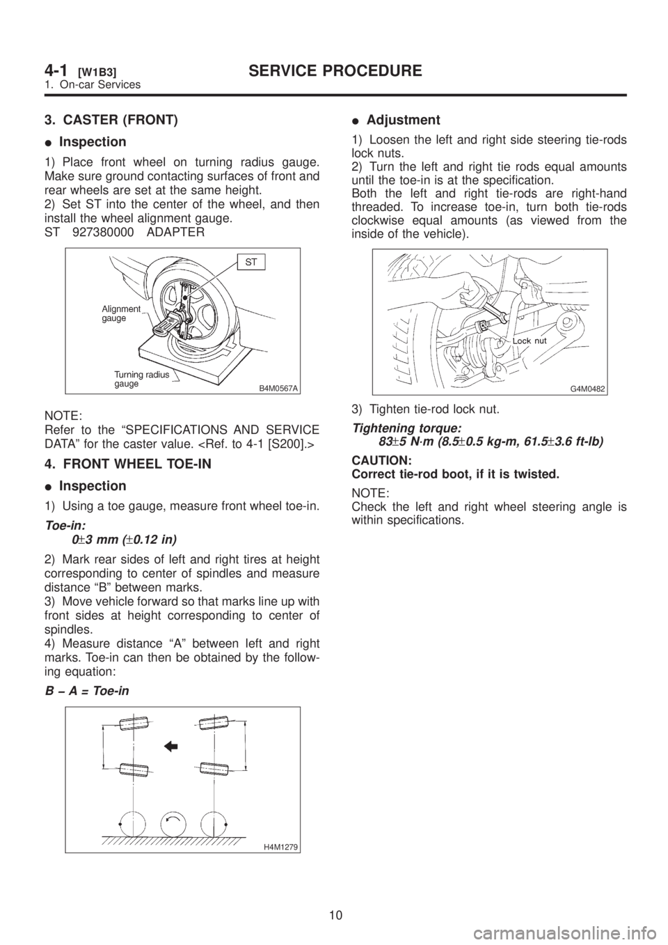
IInspection
1) Place front wheel on turning radius gauge.
Make sure ground contacting surfaces of front and
rear wheels are set at the same height.
2) Set ST into the center of the wheel, and then
install the wheel alignment gauge.
ST 927380000 ADAPTER
B4M0567A
NOTE:
Refer to the ªSPECIFICATIONS AND SERVICE
DATAº for the caster value.
4. FRONT WHEEL TOE-IN
IInspection
1) Using a toe gauge, measure front wheel toe-in.
Toe-in:
0
±3mm(±0.12 in)
2) Mark rear sides of left and right tires at height
corresponding to center of spindles and measure
distance ªBº between marks.
3) Move vehicle forward so that marks line up with
front sides at height corresponding to center of
spindles.
4) Measure distance ªAº between left and right
marks. Toe-in can then be obtained by the follow-
ing equation:
B þ A = Toe-in
H4M1279
IAdjustment
1) Loosen the left and right side steering tie-rods
lock nuts.
2) Turn the left and right tie rods equal amounts
until the toe-in is at the specification.
Both the left and right tie-rods are right-hand
threaded. To increase toe-in, turn both tie-rods
clockwise equal amounts (as viewed from the
inside of the vehicle).
G4M0482
3) Tighten tie-rod lock nut.
Tightening torque:
83
±5 N´m (8.5±0.5 kg-m, 61.5±3.6 ft-lb)
CAUTION:
Correct tie-rod boot, if it is twisted.
NOTE:
Check the left and right wheel steering angle is
within specifications.
10
4-1[W1B3]SERVICE PROCEDURE
1. On-car Services
Page 715 of 1456
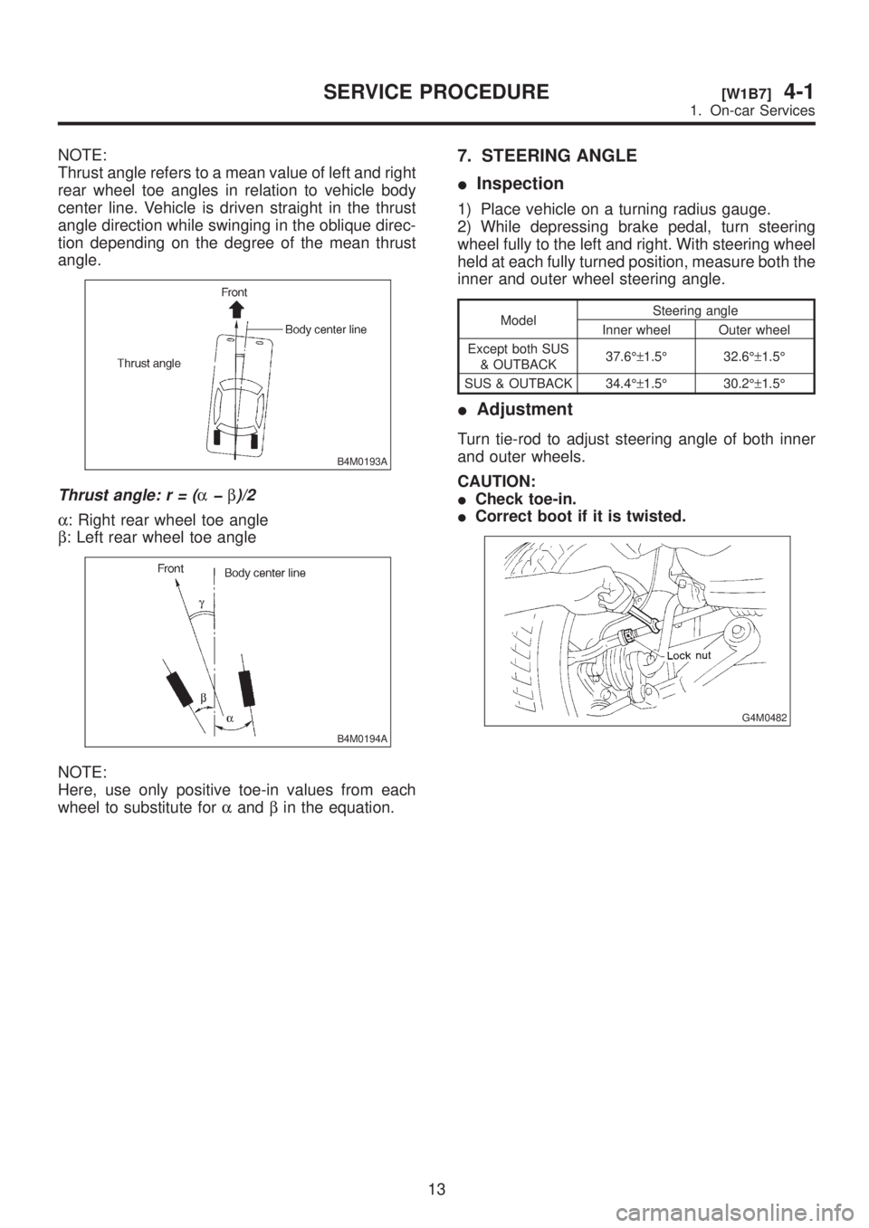
NOTE:
Thrust angle refers to a mean value of left and right
rear wheel toe angles in relation to vehicle body
center line. Vehicle is driven straight in the thrust
angle direction while swinging in the oblique direc-
tion depending on the degree of the mean thrust
angle.
B4M0193A
Thrust angle:r=(aþb)/2
a: Right rear wheel toe angle
b: Left rear wheel toe angle
B4M0194A
NOTE:
Here, use only positive toe-in values from each
wheel to substitute foraandbin the equation.
7. STEERING ANGLE
IInspection
1) Place vehicle on a turning radius gauge.
2) While depressing brake pedal, turn steering
wheel fully to the left and right. With steering wheel
held at each fully turned position, measure both the
inner and outer wheel steering angle.
ModelSteering angle
Inner wheel Outer wheel
Except both SUS
& OUTBACK37.6ɱ1.5É 32.6ɱ1.5É
SUS & OUTBACK 34.4ɱ1.5É 30.2ɱ1.5É
IAdjustment
Turn tie-rod to adjust steering angle of both inner
and outer wheels.
CAUTION:
ICheck toe-in.
ICorrect boot if it is twisted.
G4M0482
13
[W1B7]4-1SERVICE PROCEDURE
1. On-car Services
Page 726 of 1456
B: INSPECTION
1) Check bushing for cracks, fatigue or damage.
2) Check stabilizer link for deformities, cracks, or
damage, and bushing for protrusions from the hole
of stabilizer link and its play.
C: INSTALLATION
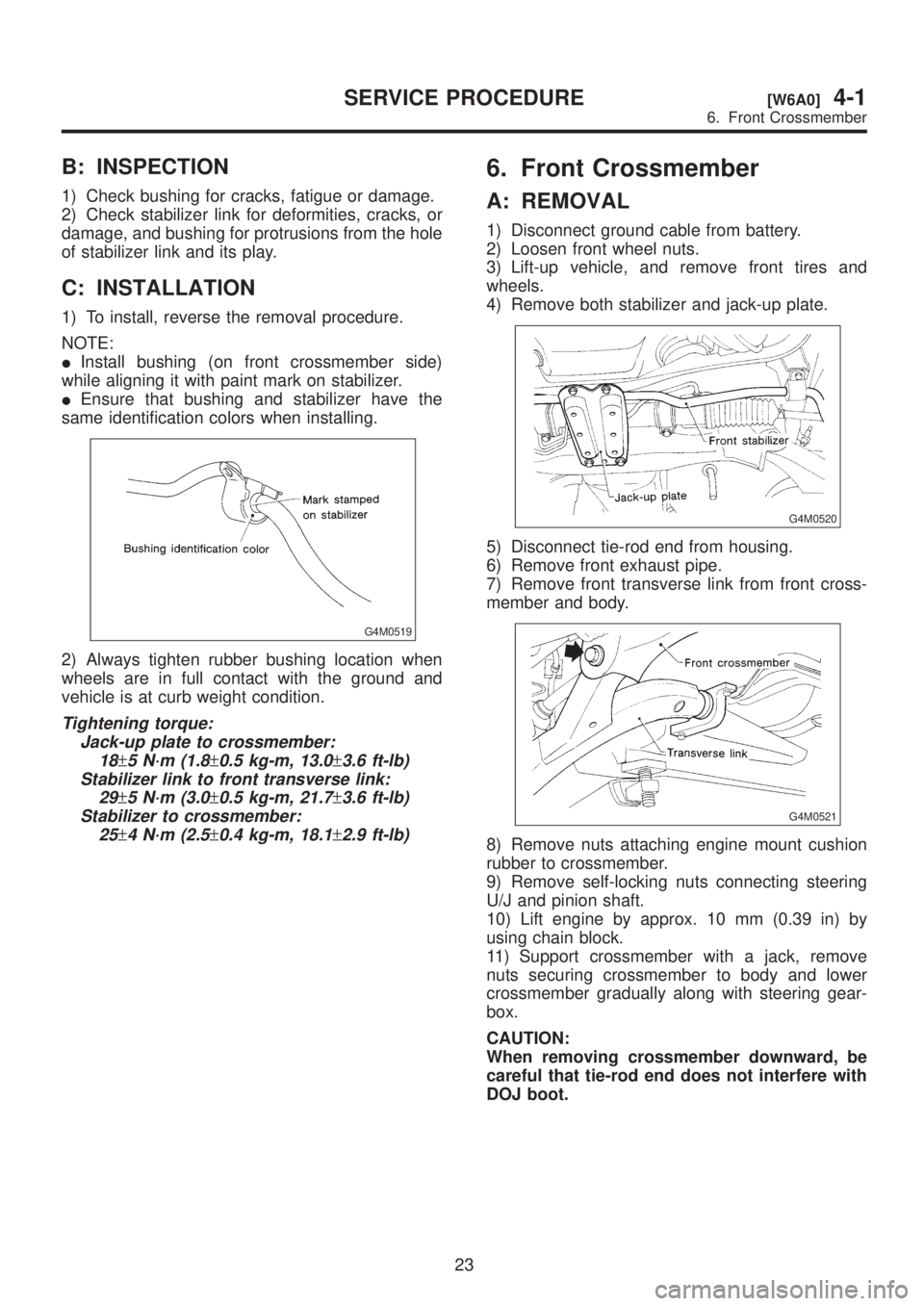
1) To install, reverse the removal procedure.
NOTE:
IInstall bushing (on front crossmember side)
while aligning it with paint mark on stabilizer.
IEnsure that bushing and stabilizer have the
same identification colors when installing.
G4M0519
2) Always tighten rubber bushing location when
wheels are in full contact with the ground and
vehicle is at curb weight condition.
Tightening torque:
Jack-up plate to crossmember:
18
±5 N´m (1.8±0.5 kg-m, 13.0±3.6 ft-lb)
Stabilizer link to front transverse link:
29
±5 N´m (3.0±0.5 kg-m, 21.7±3.6 ft-lb)
Stabilizer to crossmember:
25
±4 N´m (2.5±0.4 kg-m, 18.1±2.9 ft-lb)
6. Front Crossmember
A: REMOVAL
1) Disconnect ground cable from battery.
2) Loosen front wheel nuts.
3) Lift-up vehicle, and remove front tires and
wheels.
4) Remove both stabilizer and jack-up plate.
G4M0520
5) Disconnect tie-rod end from housing.
6) Remove front exhaust pipe.
7) Remove front transverse link from front cross-
member and body.
G4M0521
8) Remove nuts attaching engine mount cushion
rubber to crossmember.
9) Remove self-locking nuts connecting steering
U/J and pinion shaft.
10) Lift engine by approx. 10 mm (0.39 in) by
using chain block.
11) Support crossmember with a jack, remove
nuts securing crossmember to body and lower
crossmember gradually along with steering gear-
box.
CAUTION:
When removing crossmember downward, be
careful that tie-rod end does not interfere with
DOJ boot.
23
[W6A0]4-1SERVICE PROCEDURE
6. Front Crossmember