Page 17 of 90

Downloaded from www.Manualslib.com manuals search engine WIRING
Air bags and seat belt pretensioners
88
Refitting
To refit it, position the sensor using its lug and
mount it to the vehicle before reconnecting the
connector(tightening torque : 0.8 daN.m).
After connecting its connector, carry out a check
using the fault finding tool.
Unlock the computer if everything is correct,
otherwise see the"Fault Finding" section.
Connection
Track Description
1 Sensor supply
2 Earth
3 Not used
OPERATION ON THE TRIGGERING LINES
In the event of a fault noted on one of these lines,
the component must be replaced and not repai-
red.
This safety device can not tolerate any conventio-
nal repair operation on the wiring or connectors.
The air bag and pretensioner triggering lines are
integrated in the passenger compartment wiring
harness. In order to make repairs easier, the re-
placement method consists of cutting the two ex-
tremities of the faulty wiring and making the
new wiring follow the same route along the pas-
senger compartment wiring harness.
IMPORTANT: when refitting the new wiring, en-
sure that it is not subject to damage and that the
original cleanliness has been respected.
Special case : the connector with lugs
A series of vehicles are fitted with a red connector
with lugs(A) passenger air bag module side.
16008R
To disconnect it, carefully use a small screwdriver
as a lever , so as not to damage the lugs .
In the event of the lugs breaking, replace the
connector using the kit part number : 77 01 206
210 using the following method.
88-15
Page 18 of 90

Downloaded from www.Manualslib.com manuals search engine WIRING
Air bags and seat belt pretensioners
88
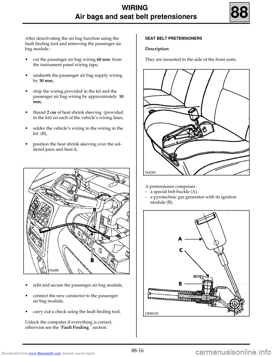
After deactivating the air bag function using the
fault finding tool and removing the passenger air
bag module :
• cut the passenger air bag wiring 60 mm from
the instrument panel wiring tape,
• unsheath the passenger air bag supply wiring
by 30 mm,
• strip the wiring provided in the kit and the
passenger air bag wiring by approximately10
mm,
• thread 2 cm of heat shrink sleeving (provided
in the kit) on each of the vehicle’s wiring lines,
• solder the vehicle’s wiring to the wiring in the
kit (B),
• position the heat shrink sleeving over the sol-
dered joins and heat it,
15668R
• refit and secure the passenger air bag module,
• connect the new connector to the passenger
air bag module,
• carry out a check using the fault finding tool.
Unlock the computer if everything is correct,
otherwise see the "Fault Finding " section.
SEAT BELT PRETENSIONERS
Description
They are mounted to the side of the front seats.
96438S
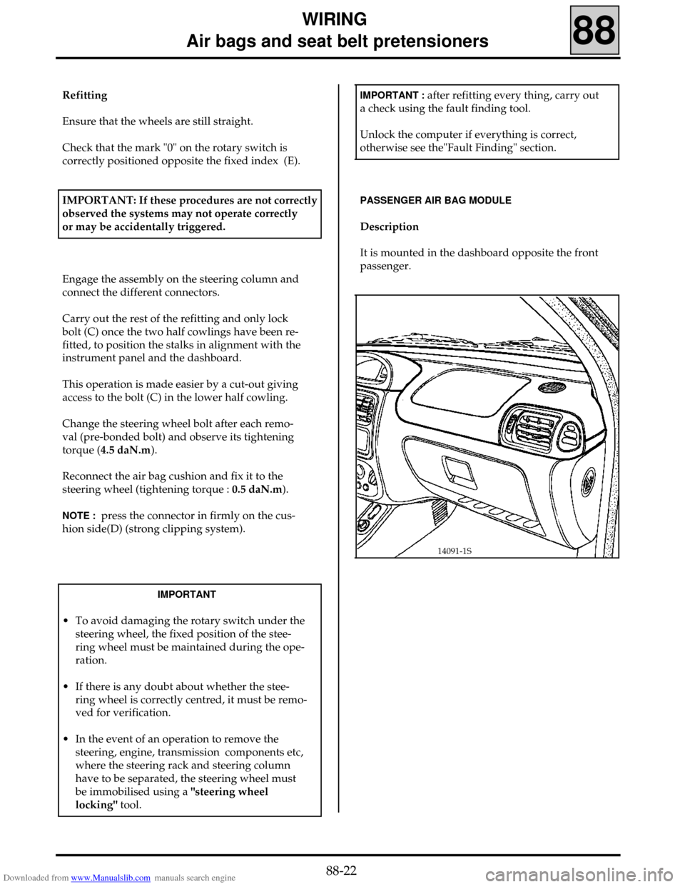
A pretensioner comprises :
- a special belt buckle (A),
- a pyrotechnic gas generator with its ignition
module (B).
DI8801R
88-16
Page 19 of 90

Downloaded from www.Manualslib.com manuals search engine WIRING
Air bags and seat belt pretensioners
88
When triggered, the system can retract the buckle
by 70 mm (maximum).
DI8802
The pretensioner’s components can not be
separated.
NOTE : this system is operational when the
ignition has been switched on.
Removal
IMPORTANT:The pyrotechnic systems (pretensio-
ners or air bags) must not be handled when near a
heat source or a flame because there is a risk that
the system will be triggered.
IMPORTANT
Before removing a pretensioner, lock the
computer using the fault finding tool.
When this function is activated, all trigger lines
are inhibited, the air bag warning light on the ins-
trument panel is illuminated.
Remove:
- the pretensioner connector located under the
front seat,
- the pretensioner assembly, after having remo-
ved the protective trim.
IMPORTANT : before scrapping an untriggered
pretensioner module, it
MUST be destroyed in ac-
cordance with the method described in the
"Destruction Procedure" section (except parts
which can be returned under warranty).
Refitting
Observe the wiring routing and the mounting
points under the seat.
NOTE : press the connector in firmly on the pre-
tensioner side (C) (strong clipping system).
IMPORTANT : after replacing the faulty parts and
reconnecting the connectors, carry out a check
using the fault finding tool.
Unlock the computer if everything is correct,
otherwise see the"Fault Finding" section.
REMINDER: the computer in these vehicles can wi-
thstand several triggerings. Therefore, it does not
have to be replaced after every triggering of the
air bag(s) or pretensioners (see "Computer" sec-
tion).
88-17
Page 20 of 90
Downloaded from www.Manualslib.com manuals search engine WIRING
Air bags and seat belt pretensioners
88
SEAT BELTS
When the pretensioners are triggered one or both
of the front seat belts must systematically be re-
placed if it was fastened when pretensioning took
place (the seat belt must be replaced if there are
any doubts about whether it was worn).
The physical forces applied to the catch affect the
inertia reel and may damage the reel mechanism.
DRIVER’S AIR BAG
Description
It is located in the steering wheel cushion.
14035S
It comprises :
- an inflatable bag,
- a pyrotechnic gas generator and ignition
module.
These components cannot be separated.
96310-1S
In order to work, the inflatable bag tears through
the steering wheel cover.
NOTE : this system is operational after the ignition
has been switched on.
88-18
Page 21 of 90

Downloaded from www.Manualslib.com manuals search engine WIRING
Air bags and seat belt pretensioners
88
IMPORTANT : before removing the air bag cus-
hion, lock the computer using the fault finding
tool.
When this operation is activated, all the trigge-
ring lines are inhibited, the air bag warning light
on the instrument panel is illuminated
Removal
IMPORTANT:The pyrotechnic systems (pretensio-
ners or air bags) must not be handled when near a
heat source or a flame because there is a risk that
the system will be triggered.
IMPORTANT : When removing the steering wheel,
the air bag connector must be disconnected (D)
(see below).
The air bag is fitted with a connector which short
circuits when it is disconnected to avoid incorrect
triggering .
Remove the air bag cushion by its two torx bolts
located behind the steering wheel and disconnect
its connector (D).
14036R1
IMPORTANT : before scrapping an untriggered air
bag module, it
MUST be destroyed in accordance
with the method described in the "Destruction
Procedure" section
Refitting
Reconnect the air bag cushion and mount it to
the steering wheel (tightening torque : 0.5
daN.m).
NOTE :press the connector in firmly on the cus-
hion side (D) (strong clipping system).
IMPORTANT : after refitting everything,carry out
a check using the fault finding tool .
Unlock the computer if everything is correct,
otherwise see the"Fault Finding" section.
REMINDER: the computer in these vehicles can wi-
thstand several triggerings. Therefore, it does not
have to be replaced after every triggering of the
air bag(s) or pretensioners (see "Computer" sec-
tion).
88-19
Page 22 of 90

Downloaded from www.Manualslib.com manuals search engine WIRING
Air bags and seat belt pretensioners
88
IMPORTANT : before removing the air bag cus-
hion, lock the computer using the fault finding
tool.
When this operation is activated, all the trigge-
ring lines are inhibited, the air bag warning light
on the instrument panel is illuminated.
ROTARY SWITCH
The rotary switch ensures the electrical connec-
tion between the steering column and the stee-
ring wheel.
It consists of a strip with two conducting tracks
(air bag) of which the length is long enough to al-
low 2.5 turns of the steering wheel (full lock plus
safety) for each side.
Removal
IMPORTANT:The pyrotechnic systems (pretensio-
ners or air bags) must not be handled when near a
heat source or a flame because there is a risk that
the system will be triggered.
IMPORTANT : When removing the steering wheel,
the air bag connector must be disconnected (D)
(see below). The air bag is fitted with a connector
which short circuits when it is disconnected to
avoid incorrect triggering .
14036R1
Remove :
- the air bag cushion by its two torx bolts located
behind the steering wheel and disconnect its
connector (D).
- the steering wheel bolt,
- the steering wheel after positioning the wheels
straight,
- the half cowlings (three bolts).
Disconnect the stalks (windscreen wipers and
lights) and the rotary switch connector.
Before removing the assembly, the rotary switch
position must be noted:
- by ensuring that the wheels are straight during
removal in order to position the length of the
strip in the centre ,
- by checking that the mark "0" is correctly posi-
tioned opposite the fixed index (E).
88-20
Page 23 of 90
Downloaded from www.Manualslib.com manuals search engine WIRING
Air bags and seat belt pretensioners
88
Valéo fitting
14057R
Lucas fitting
14056R
Slacken bolt (C), then tap the screwdriver sharply
to loosen the cone and release assembly from the
steering column .
14039R
88-21
Page 24 of 90

Downloaded from www.Manualslib.com manuals search engine WIRING
Air bags and seat belt pretensioners
88
Refitting
Ensure that the wheels are still straight.
Check that the mark "0" on the rotary switch is
correctly positioned opposite the fixed index (E).
IMPORTANT: If these procedures are not correctly
observed the systems may not operate correctly
or may be accidentally triggered.
Engage the assembly on the steering column and
connect the different connectors.
Carry out the rest of the refitting and only lock
bolt (C) once the two half cowlings have been re-
fitted, to position the stalks in alignment with the
instrument panel and the dashboard.
This operation is made easier by a cut-out giving
access to the bolt (C) in the lower half cowling.
Change the steering wheel bolt after each remo-
val (pre-bonded bolt) and observe its tightening
torque (4.5 daN.m).
Reconnect the air bag cushion and fix it to the
steering wheel (tightening torque : 0.5 daN.m).
NOTE : press the connector in firmly on the cus-
hion side(D) (strong clipping system).
IMPORTANT
• To avoid damaging the rotary switch under the
steering wheel, the fixed position of the stee-
ring wheel must be maintained during the ope-
ration.
• If there is any doubt about whether the stee-
ring wheel is correctly centred, it must be remo-
ved for verification.
• In the event of an operation to remove the
steering, engine, transmission components etc,
where the steering rack and steering column
have to be separated, the steering wheel must
be immobilised using a "steering wheel
locking" tool.
IMPORTANT : after refitting every thing, carry out
a check using the fault finding tool.
Unlock the computer if everything is correct,
otherwise see the"Fault Finding" section.
PASSENGER AIR BAG MODULE
Description
It is mounted in the dashboard opposite the front
passenger.
14091-1S
88-22