1999 LAND ROVER DISCOVERY wiring
[x] Cancel search: wiringPage 1119 of 1529
PANEL REPAIRS
77-2-52 REPAIRS
Refit
1.Position and secure wiring.
2.Fit and tighten bolts securing body to chassis to
45 Nm (33 lbf.ft).
3.Fit tail door aperture seal.
4.Fit head lining rear trim finisher.
5.Fit loadspace carpet retainer.
6.Fit tail door tread plate.
7.Fit rear door aperture seals.
8.Fit tread plate to rear door apertures.
9.Fit exhaust tail pipe heatshields.
10.Fit mud flap bracklets and mud flaps.
11.Fit rear bumper assembly.
+ EXTERIOR FITTINGS, REPAIRS,
Bumper assembly - rear - up to 03MY.
12.Fit rear carpet.
+ INTERIOR TRIM COMPONENTS,
REPAIRS, Carpet - rear.
13.Fit rear seats.
+ SEATS, REPAIRS, Seat - rear.
14.Fit loadspace carpet.
+ INTERIOR TRIM COMPONENTS,
REPAIRS, Carpet - loadspace.
15.Connect leads/multiplug to alternator.
16.Connect battery leads, negative lead last.
Rear floor (rear section)
In this procedure, the cross member rear assembly,
cross member outer rear panel, cross member
closing rear panel, 'E' post assembly, 'E' post closing
assembly and the panel body side assembly are
replaced in conjunction with the rear floor (rear
section).
Remove
1.Disconnect both battery leads, negative lead
first.
2.Disconnect leads/multiplug from alternator.
3.Remove cross member rear assembly.
+ PANEL REPAIRS, REPAIRS, Cross
member rear assembly.
4.Remove mud flap mounting brackets.
5. LH side: Remove exhaust heatshield from rear
floor.
Repair
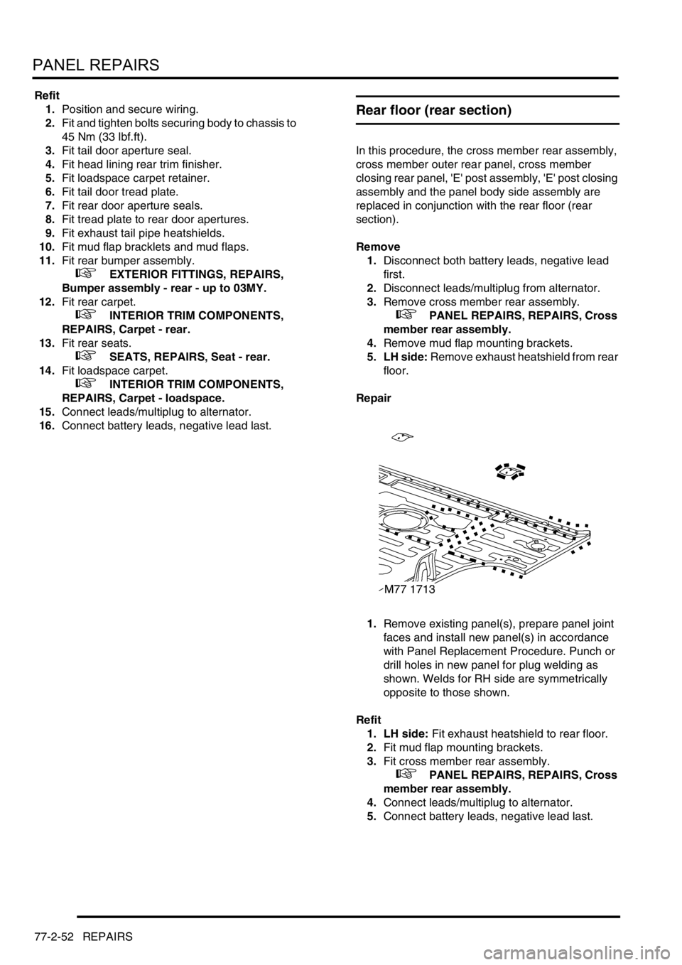
1.Remove existing panel(s), prepare panel joint
faces and install new panel(s) in accordance
with Panel Replacement Procedure. Punch or
drill holes in new panel for plug welding as
shown. Welds for RH side are symmetrically
opposite to those shown.
Refit
1. LH side: Fit exhaust heatshield to rear floor.
2.Fit mud flap mounting brackets.
3.Fit cross member rear assembly.
+ PANEL REPAIRS, REPAIRS, Cross
member rear assembly.
4.Connect leads/multiplug to alternator.
5.Connect battery leads, negative lead last.
Page 1120 of 1529
PANEL REPAIRS
REPAIRS 77-2-53
Rear floor (RH/LH section)
In this procedure, the cross member rear assembly,
cross member outer rear panel (RH/LH section),
cross member closing rear panel, 'E' post assembly,
'E' post closing assembly and the panel body side
assembly are replaced in conjunction with the rear
floor (RH/LH section).
Remove
1.Disconnect both battery leads, negative lead
first.
2.Disconnect leads/multiplug from alternator.
3.Remove cross member rear assembly.
+ PANEL REPAIRS, REPAIRS, Cross
member rear assembly.
4.Remove mud flap mounting brackets.
5. LH side: Remove exhaust heatshield from rear
floor.
Repair
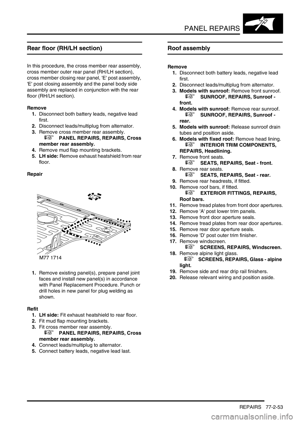
1.Remove existing panel(s), prepare panel joint
faces and install new panel(s) in accordance
with Panel Replacement Procedure. Punch or
drill holes in new panel for plug welding as
shown.
Refit
1. LH side: Fit exhaust heatshield to rear floor.
2.Fit mud flap mounting brackets.
3.Fit cross member rear assembly.
+ PANEL REPAIRS, REPAIRS, Cross
member rear assembly.
4.Connect leads/multiplug to alternator.
5.Connect battery leads, negative lead last.
Roof assembly
Remove
1.Disconnect both battery leads, negative lead
first.
2.Disconnect leads/multiplug from alternator.
3. Models with sunroof: Remove front sunroof.
+ SUNROOF, REPAIRS, Sunroof -
front.
4. Models with sunroof: Remove rear sunroof.
+ SUNROOF, REPAIRS, Sunroof -
rear.
5. Models with sunroof: Release sunroof drain
tubes and position aside.
6. Models with fixed roof: Remove head lining.
+ INTERIOR TRIM COMPONENTS,
REPAIRS, Headlining.
7.Remove front seats.
+ SEATS, REPAIRS, Seat - front.
8.Remove rear seats.
+ SEATS, REPAIRS, Seat - rear.
9.Remove rear headrests, if fitted.
10.Remove roof bars, if fitted.
+ EXTERIOR FITTINGS, REPAIRS,
Roof bars.
11.Remove tread plates from front door apertures.
12.Remove 'A' post lower trim panels.
13.Remove front door aperture seals.
14.Remove tread plates from rear door apertures.
15.Remove rear door aperture seals.
16.Remove 'D' post outer trim finisher.
17.Remove windscreen.
+ SCREENS, REPAIRS, Windscreen.
18.Remove alpine light glass.
+ SCREENS, REPAIRS, Glass - alpine
light.
19.Remove side and rear drip rail finishers.
20.Release relevant wiring and position aside.
Page 1121 of 1529
PANEL REPAIRS
77-2-54 REPAIRS
Repair
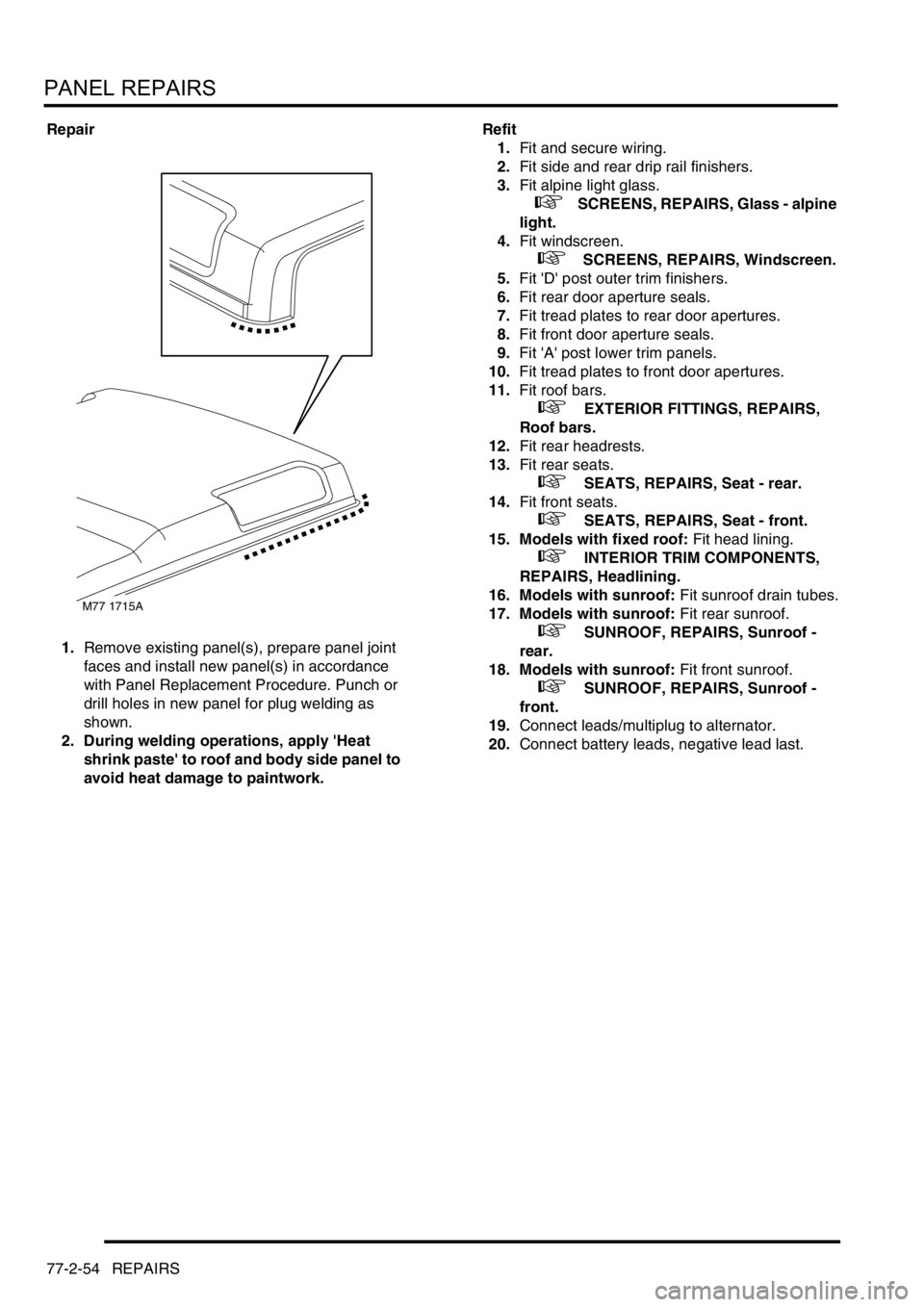
1.Remove existing panel(s), prepare panel joint
faces and install new panel(s) in accordance
with Panel Replacement Procedure. Punch or
drill holes in new panel for plug welding as
shown.
2. During welding operations, apply 'Heat
shrink paste' to roof and body side panel to
avoid heat damage to paintwork.Refit
1.Fit and secure wiring.
2.Fit side and rear drip rail finishers.
3.Fit alpine light glass.
+ SCREENS, REPAIRS, Glass - alpine
light.
4.Fit windscreen.
+ SCREENS, REPAIRS, Windscreen.
5.Fit 'D' post outer trim finishers.
6.Fit rear door aperture seals.
7.Fit tread plates to rear door apertures.
8.Fit front door aperture seals.
9.Fit 'A' post lower trim panels.
10.Fit tread plates to front door apertures.
11.Fit roof bars.
+ EXTERIOR FITTINGS, REPAIRS,
Roof bars.
12.Fit rear headrests.
13.Fit rear seats.
+ SEATS, REPAIRS, Seat - rear.
14.Fit front seats.
+ SEATS, REPAIRS, Seat - front.
15. Models with fixed roof: Fit head lining.
+ INTERIOR TRIM COMPONENTS,
REPAIRS, Headlining.
16. Models with sunroof: Fit sunroof drain tubes.
17. Models with sunroof: Fit rear sunroof.
+ SUNROOF, REPAIRS, Sunroof -
rear.
18. Models with sunroof: Fit front sunroof.
+ SUNROOF, REPAIRS, Sunroof -
front.
19.Connect leads/multiplug to alternator.
20.Connect battery leads, negative lead last.
M77 1715A
Page 1161 of 1529

HEATING AND VENTILATION
80-4DESCRIPTION AND OPERATION
Air inlet duct
RH drive shown, LH drive similar
1Air outlet
2Resistor pack
3Wiring harness
4Blower
5Blower relay6Recirculated air servo motor
7Control flap operating mechanism
8Recirculated air inlet
9Recirculated air inlet
10Fresh air inlet
The air inlet duct is installed behind the fascia, on the passenger's side. The air inlet duct is connected to the plenum
to provide the fresh air inlet. Two grilles in the air inlet duct provide recirculated air inlets from the cabin. Two control
flaps, operated by a servo motor, open and close the fresh and recirculated air inlets to control the source of incoming
air. Operation of the servo motor is controlled by a switch on the control panel.
The blower is installed between the air inlets and the outlet to the heater assembly, and consists of an open hub,
centrifugal fan powered by an electric motor. Operation of the blower is controlled by a slider switch on the control
panel, via a blower relay mounted on the air inlet duct and a resistor pack. The resistor pack is installed in the air outlet
from the blower fan, so that any heat generated is dissipated by the air flow. A wiring harness on the air inlet duct
connects the servo motor, blower motor, blower relay and resistor pack to the vehicle wiring.
Page 1167 of 1529
HEATING AND VENTILATION
80-10DESCRIPTION AND OPERATION
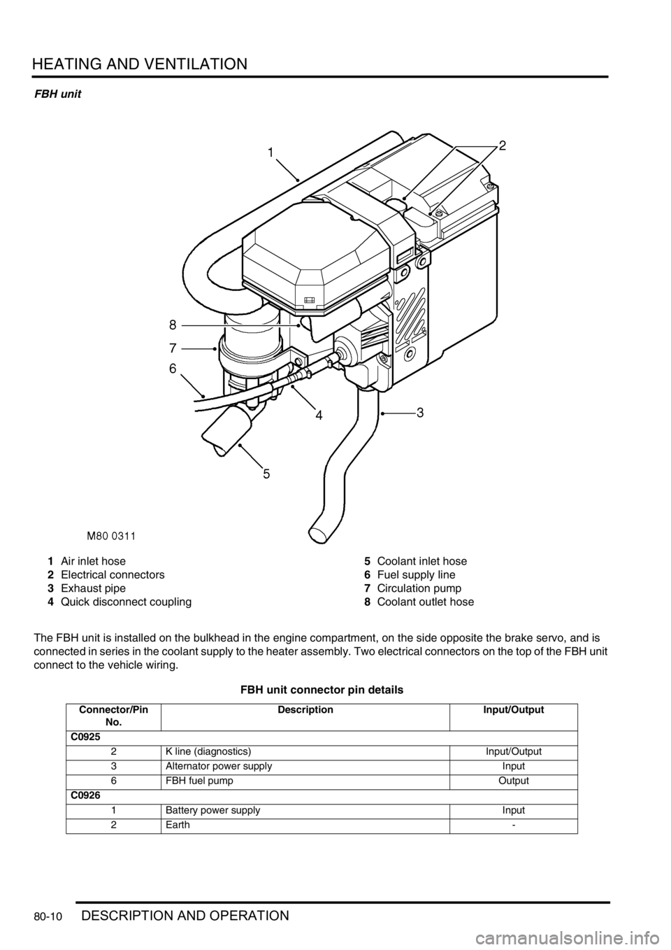
FBH unit
1Air inlet hose
2Electrical connectors
3Exhaust pipe
4Quick disconnect coupling5Coolant inlet hose
6Fuel supply line
7Circulation pump
8Coolant outlet hose
The FBH unit is installed on the bulkhead in the engine compartment, on the side opposite the brake servo, and is
connected in series in the coolant supply to the heater assembly. Two electrical connectors on the top of the FBH unit
connect to the vehicle wiring.
FBH unit connector pin details
Connector/Pin
No.Description Input/Output
C0925
2 K line (diagnostics) Input/Output
3 Alternator power supply Input
6 FBH fuel pump Output
C0926
1 Battery power supply Input
2Earth -
Page 1306 of 1529
BODY CONTROL UNIT
DESCRIPTION AND OPERATION 86-3-19
Operation
For IDM inputs which are also inputs for BCU functions, the delay before the BCU recognises the change in input
status is less than 250 ms. The BCU uses a debounce algorithm to ignore changes in input having a duration less
than 100 ms with the exception of automatic gearbox W, X, Y, Z inputs, which have a debounce period of 33 ms.
Transit mode
To prevent excessive battery drain during transit to overseas markets, the vehicle is placed in a transit mode.
To exit the transit mode, simultaneously hold down the heated rear window switch and the rear fog lamp switch, turn
the ignition switch from 0 to II and, after a minimum of 2 seconds, release the switches.
Transit mode can be entered using TestBook. When TestBook communicates with the BCU for diagnostics related to
BCU operation, it first checks that the vehicle is not in transit mode.
Anti-theft system
The BCU uses the driver's door key lock and unlock switches to activate and deactivate the security system. The
driver's door lock is also used for entering the EKA.
+ ALARM SYSTEM AND HORN, DESCRIPTION AND OPERATION, Description.
Immobilisation
For immobilisation, the BCU disables the starter motor relay. When the engine is cranking, the ECM looks for a coded
signal from the BCU. If the signal is not received within one second of cranking, the fuel supply to the engine is
stopped and the injectors are disabled. This also prevents unburnt fuel from entering the catalyst.
If the BCU is disconnected, the engine starter motor will remain isolated by the starter motor relay and the ECM will
remain immobilised. The main wiring for the system is contained within the main harness which is relatively
inaccessible, so preventing intruders from disabling the system by cutting the wires for the immobilisation system.
Once the immobiliser has been activated, destruction of the trigger device or the wiring to it will not disarm the system.
The RF transmitter communicates to the BCU via the RF receiver using a 70 bit code. Pressing the unlock button on
the transmitter will re-mobilise the vehicle. The RF transponder is integrated into the metal key assembly, inserting
the key into the ignition switch will induce a signal in the exciter coil to re-mobilise the vehicle.
Anti-theft alarm
The alarm system provides a warning of unauthorised access to the vehicle and includes perimetric and volumetric
monitoring under the control of the BCU.
The perimetric protection system detects opening of all doors, tail door and bonnet and will also detect the operation
of the ignition key switch. The following conditions must be satisfied before the BCU will operate all of the functions
of perimetric protection:
lAll doors and hinged panels are in the closed position.
lIgnition key out of the ignition switch.
lInertia switch is not tripped.
If all conditions are not satisfied the BCU will enter a mislock condition.
The volumetric sensor uses two ultrasonic sensors mounted in the headlining to detect movement within the vehicle.
The alarm will trigger when the sensor signals the BCU for 200 ms or greater. Within a single setting period the alarm
system will allow a maximum of 10 triggers as a result of any combination of sensor inputs. It is possible to lock the
vehicle without enabling the volumetric alarm by using the key. The same conditions needed to satisfy enabling of the
perimetric protection system is also needed to enable volumetric protection.
When the alarm system is set the BCU checks the status of all the inputs from the door and bonnet switches to ensure
the integrity of the vehicle before setting the alarm system into operational mode. In some markets, when the alarm
is set the BCU sends a signal to the IDM which will cause the direction indicators to flash three times for a duration of
3 seconds.
If the sensors are triggered the BCU will activate an alarm sounder to provide an audible warning of a theft attempt.
The activation period of the alarm sounder is 25 to 30 seconds. The duty cycle of the alarm sounder is 50:50 ± 10%.
Page 1343 of 1529

ALARM SYSTEM AND HORN
86-4-20 DESCRIPTION AND OPERATION
Super locking
Super locking prevents the use of the interior door handles to unlock and open the vehicle doors. This prevents the
doors from being opened if the window be smashed in an attempt to gain access to the vehicle.
There are four configurations for super locking:
lNo super locking.
lSuper locking on single handset press only (no key activated super locking).
lSuper locking on single handset press or single key turn.
lSuper locking on double handset press or double key turn.
To super lock, press the lock button on the handset once or twice within one second depending on system
configuration. In some configurations, it is also possible to super lock the vehicle using the key in the driver's door.
This also may require one or two turns of the key in the lock direction. If two turns of the key are required to activate
super locking, the two turns must occur within one second of each other.
In order to super lock the vehicle, the following conditions must be met:
lAll door are closed.
lThe ignition is off.
lThe fuel cut-off switch is not tripped.
Partial arming
Partial arming allows protection of as much of the vehicle as possible if the alarm is armed with one or more doors or
the bonnet open.
Partial arming allows the vehicle alarm to be armed even if the following conditions exist. When the bonnet or door is
closed, the BCU activates the perimetric alarm and the volumetric alarm after 15 seconds have elapsed:
lThe bonnet is not closed: If the bonnet is open when the alarm is armed, the BCU activates super locking and
volumetric sensing. In this condition, the alarm enters a partially armed state. All other functions of the alarm are
active and the BCU monitors the bonnet for a change of state. If the bonnet closes, the system is completely
armed.
lThe passenger door, a rear door or the tail door is not closed: If a door is open when the alarm is armed, the BCU
does not activate super locking or volumetric sensing. In this condition the alarm enters a partially armed state.
All other alarm functions are armed and the BCU monitors the open door. If the door closes volumetric sensing
and super locking become active.
lFailure of a door latch switch: If a short circuit in the door latch switch occurs, the BCU presumes the door is not
closed. In this situation the BCU does not activate super locking or volumetric sensing. All other alarm functions
are armed.
lDamaged wiring harness: If a short circuit in the wiring harness for the door latch switch occurs, the BCU
presumes the door is not closed and does not activate super locking or volumetric sensing; all other alarm
functions are armed. If an open circuit in the wiring harness for the door latch switch occurs, the BCU presumes
the door is closed and arms the alarm as normal.
Mislock
Mislock alerts the driver that a failed attempt has been made to lock the vehicle because of the doors or the bonnet
not being fully closed.
There are six audible configurations for mislock:
lNo audible warning.
lAlarm sounder.
lVehicle horn.
lAlarm sounder and vehicle horn.
lBBUS.
lAlarm sounder, vehicle horn and BBUS.
When a failed attempt has been made to lock the vehicle, the audible warning device is switched on for 50 ms and
off for 200 ms. The BCU allows the audible warning device to operate 3 times.
Page 1376 of 1529

IN CAR ENTERTAINMENT
DESCRIPTION AND OPERATION 86-6-9
Inputs and outputs
The radio cassette player receives a mute signal from the telephone system if a call is received, when the call finishes
the mute is removed and the system resumes play. Inputs are also received from the steering wheel control system
(mid line and high line sytems). When the system is turned on, the high line systems radio cassette player:
lsends a 'power on enable' to the power amplifier
lsends an 'enable' signal to the radio headphone amplifiers.
On the high line system the radio cassette player also sends and receives signals from the CD-autochanger and rear
headphone amplifiers (if fitted). On high line systems the radio cassette player sends audio signals to the power
amplifier.
Remote radio steering wheel controls (midline and high line systems)
The remote radio control switch is located on the LH side of the steering wheel and is secured with two screws. The
wiring from the remote radio control switch plugs in to a connector that is part of the steering wheel rotary coupler.
Operation of the remote radio control switches allow the driver to control the ICE without releasing the steering wheel.
Volume, mode and selection functions can be carried out using the steering wheel mounted control switches. Control
inputs from the remote radio control switches are sent to the radio cassette player.
C0098
1 Telephone mute Input
2 Steering wheel remote radio controls Input
3 Steering wheel remote radio controls Output
4 Permanent battery feed Input
5 System enable Output
6 Illumination Input
7 Auxilary feed Input
8 Earth Input
C0921 (high line systems)
1 Radio headphone left channel Output +
2 Radio headphone right channel Output +
3 Telephone audio Input +
4 Radio headphone left channel Output -
5 Radio headphone right channel Output -
6 Telephone audio Input -
C0922 (high line systems)
7 Radio headphone active Input
8 I-BUS communications Input/Output
9 Audio amplifier spatial imaging enable Output
10 Radio headphone LH remote control Input
11 Radio headphone RH remote control Input
12 Headphone remote controls feed Output
C1354 (high line systems)
13 CD-autochanger audio left channel Input +
14 CD-autochanger audio right channel Input +
15 CD-autochanger audio earth Output
16 CD-autochanger audio left channel Input -
17 CD-autochanger audio right channel Input -
18 Not Used
19 CD-autochanger I-BUS communications link Input/Output
20 CD-autochanger permanent feed Output