Page 356 of 1529

ENGINE MANAGEMENT SYSTEM - V8
DESCRIPTION AND OPERATION 18-2-57
Low fuel level signal
When the fuel level in the fuel tank becomes low enough to illuminate the low fuel level warning lamp in the instrument
cluster, the instrument cluster generates a low fuel level signal. If the low fuel level signal is present during the ECM
misfire detection function the ECM can use it to check for a 'false misfire'.
Conditions
The fuel sender generates the low fuel level signal when the fuel sender resistance is greater than 158 ± 8 ohms.
Function
The illumination of the low fuel level warning lamp in the instrument cluster triggers the low fuel level signal to be sent
to the ECM. This signal is processed via pin 8 of connector C0637 of the ECM.
Should a misfire occur while the fuel level is low, the following fault code may be evident and can be retrieved by
TestBook.
Coolant temperature gauge signal
The ECM controls the temperature gauge in the instrument cluster. The ECM sends a coolant temperature signal to
the temperature gauge in the instrument cluster in the form of a PWM square wave signal.
The frequency of the signal determines the level of the temperature gauge.
Conditions
The ECM operates the PWM signal under the following parameters:
l-40 °C (-40 °F) = a pulse width of 768 µs.
l140 °C (284 °F) = a pulse width of 4848 µs.
Function
The coolant temperature signal is an output from the ECM to the instrument cluster. The coolant temperature signal
is generated via pin 44 of connector C0636 of the ECM.
The coolant temperature signal can fail in the following ways:
lWiring short circuit to vehicle supply.
lWiring short circuit to vehicle earth.
lWiring open circuit.
In the event of a coolant temperature signal failure any of the following symptoms may be observed:
lCoolant temperature gauge will read cold at all times.
lCoolant temperature warning lamp remains on at all times.
Controller Area Network (CAN) system
The controller area network (CAN) system is a high speed serial interface between the ECM and the Electronic
Automatic Transmission (EAT) ECU. The CAN system uses a 'data bus' to transmit information messages between
the ECM and the EAT ECU. Because there are only two components in this CAN system, one will transmit information
messages and the other will receive information messages, and vice-versa.
P Code J2012 Description Land Rover Description
P1319 Misfire detected at low fuel level Misfire detected with low fuel level
Page 362 of 1529

ENGINE MANAGEMENT SYSTEM - V8
DESCRIPTION AND OPERATION 18-2-63
Description - cruise control
General
All markets have a common cruise control system. The cruise control system, when activated, regulates vehicle
speed. The system consists of an electrical sub-system and a mechanical sub-system.
The electrical sub-system consists of the following components:
lCruise control master switch (on/off switch).
lSET+ switch.
lRES switch.
lCruise control ECU.
lVacuum pump assembly.
lBrake pedal switch.
lClutch pedal switch (manual gearbox only).
lSLABS ECU (speed signal).
lBCU (brake pedal switch and automatic gearbox gear selector lever position signal).
The mechanical sub-system consists of the following components:
lPneumatic actuator.
lVacuum pump.
The cruise control ECU controls the cruise control system. It is located on the right hand A post.
The system has diagnostic capabilities through TestBook.
WARNING: To avoid the risk of losing control of the vehicle, do not use cruise control on winding, snow
covered or slippery roads, or in traffic conditions where a constant speed cannot be safely maintained. In
these conditions and at any time the system is not being used, ensure the cruise control switch is OFF.
Page 382 of 1529

ENGINE MANAGEMENT SYSTEM - V8
REPAIRS 18-2-83
Sensor - crankshaft position (CKP)
$% 18.30.12
Remove
1.Release fixings and remove battery cover.
2.Disconnect battery earth lead.
3.Raise front of vehicle.
WARNING: Do not work on or under a
vehicle supported only by a jack. Always
support the vehicle on safety stands.
4.Release fixings and remove underbelly panel.
5.Release CKP sensor multiplug from bracket.
6.Remove 2 bolts securing CKP sensor heat
shield and position aside.
7.Remove 2 nuts securing CKP sensor, remove
2 spacers, CKP sensor and sensor mounting.
8.Disconnect CKP sensor multiplug from engine
harness. Refit
1.Ensure all components are clean.
2.Connect CKP sensor multiplug to engine
harness.
3.Fit sensor mounting, CKP sensor, 2 spacers
and tighten CKP sensor retaining nuts to 6 Nm
(5 lbf.ft).
4.Fit CKP sensor heat shield and secure with
bolts.
5.Fit underbelly panel and secure with fixings.
6.Remove stand(s) and lower vehicle.
7.Connect battery earth lead.
8.Fit battery cover and secure the fixings.
9.Reset adaptions using TestBook.
Page 383 of 1529

ENGINE MANAGEMENT SYSTEM - V8
18-2-84 REPAIRS
Sensor - radiator temperature
$% 18.30.20
Remove
1.Disconnect battery earth lead.
2.Position container to collect coolant spillage.
3.Disconnect multiplug from sensor.
4.Remove sensor and discard sealing washer.
Refit
1.Fit new sealing washer to sensor.
2.Fit and tighten sensor.
3.Connect multiplug to sensor.
4.Refill cooling system.
5.Connect battery earth lead.
Sensor - camshaft position (CMP)
$% 18.30.24
Remove
1.Release fixings and remove battery cover.
2.Disconnect battery earth lead.
3.Raise front of vehicle.
WARNING: Do not work on or under a
vehicle supported only by a jack. Always
support the vehicle on safety stands.
4.Release fixings and remove underbelly panel.
5.Remove engine oil filter.
+ ENGINE - V8, REPAIRS, Filter - oil.
6.Disconnect engine harness from CMP sensor
and release CMP sensor multiplug from
bracket.
7.Remove bolt from clamp securing CMP sensor
to timing gear cover.
8.Remove clamp and CMP sensor. Discard 'O'
ring from CMP sensor.
Refit
1.Ensure CMP sensor is clean, fit new 'O' ring
and sensor to cover.
2.Fit clamp to CMP sensor and tighten bolt to 8
Nm (6 lbf.ft).
3.Fit sensor multiplug to bracket and connect
engine harness to multiplug.
4.Fit engine oil filter.
+ ENGINE - V8, REPAIRS, Filter - oil.
5.Fit underbelly panel and secure with fixings.
6.Lower vehicle and connect battery earth lead.
7.Fit battery cover and secure with fixings.
Page 384 of 1529
ENGINE MANAGEMENT SYSTEM - V8
REPAIRS 18-2-85
Knock sensor (KS)
$% 18.30.28
Remove
1.Release fixings and remove battery cover.
2.Disconnect battery earth lead.
3.Raise front of vehicle.
WARNING: Do not work on or under a
vehicle supported only by a jack. Always
support the vehicle on safety stands.
4.Remove fixings securing underbelly panel and
remove panel.
5.Disconnect multiplug from KS.
6.Remove nut securing KS to cylinder block and
remove KS. Refit
1.Clean mating faces of KS and cylinder block.
2.Fit KS to cylinder block and tighten nut to 22
Nm (16 lbf.ft).
3.Connect multiplug to KS.
4.Fit underbelly panel and secure with fixings.
5.Remove stand(s) and lower vehicle.
6.Connect battery earth lead.
7.Fit battery cover and secure the fixings.
Page 408 of 1529
FUEL DELIVERY SYSTEM - V8
ADJUSTMENTS 19-2-11
ADJUST ME NTS
Fuel tank - drain
$% 19.55.02
Drain
1.Disconnect both leads from battery.
WARNING: Always disconnect the negative
lead first. Disconnection of the positive lead
while the negative lead is connected could
result in a short circuit through accidental
grounding and cause personal injury.
2.Connect TestBook to vehicle and depressurise
fuel system.
3.Remove fuel pump.
+ FUEL DELIVERY SYSTEM - V8,
REPAIRS, Pump - fuel.
4.Using a fuel recovery appliance, drain the fuel
from the tank into a sealed container. Follow
the manufacturers instructions for the
connection and safe use of the appliance.
Refill
1.Fit fuel pump unit.
+ FUEL DELIVERY SYSTEM - V8,
REPAIRS, Pump - fuel.
2.Refill fuel tank with extracted fuel.
3.Connect battery leads, positive lead first.
Page 412 of 1529

FUEL DELIVERY SYSTEM - V8
REPAIRS 19-2-15
Tank - fuel
$% 19.55.01
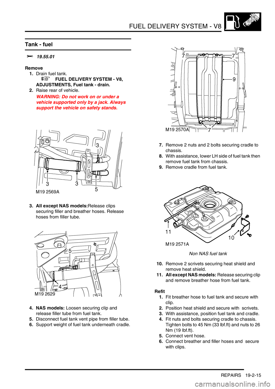
Remove
1.Drain fuel tank.
+ FUEL DELIVERY SYSTEM - V8,
ADJUSTMENTS, Fuel tank - drain.
2.Raise rear of vehicle.
WARNING: Do not work on or under a
vehicle supported only by a jack. Always
support the vehicle on safety stands.
3. All except NAS models:Release clips
securing filler and breather hoses. Release
hoses from filler tube.
4. NAS models: Loosen securing clip and
release filler tube from fuel tank.
5.Disconnect fuel tank vent pipe from filler tube.
6.Support weight of fuel tank underneath cradle. 7.Remove 2 nuts and 2 bolts securing cradle to
chassis.
8.With assistance, lower LH side of fuel tank then
remove fuel tank from chassis.
9.Remove cradle from fuel tank.
Non NAS fuel tank
10.Remove 2 scrivets securing heat shield and
remove heat shield.
11. All except NAS models: Release securing clip
and remove breather hose from fuel tank.
Refit
1.Fit breather hose to fuel tank and secure with
clip.
2.Position heat shield and secure with scrivets.
3.With assistance, position fuel tank and cradle.
4.Fit nuts and bolts securing cradle to chassis.
Tighten bolts to 45 Nm (33 lbf.ft) and nuts to 26
Nm (19 lbf.ft).
5.Connect vent hose.
6.Connect breather and filler hoses and secure
with clips.
Page 413 of 1529

FUEL DELIVERY SYSTEM - V8
19-2-16 REPAIRS
Filler tube - fuel
$% 19.55.07
Remove
1.Raise rear of vehicle.
WARNING: Do not work on or under a
vehicle supported only by a jack. Always
support the vehicle on safety stands.
2.Ensure fuel tank is less than half full. If not,
drain fuel tank to less than half full.
+ FUEL DELIVERY SYSTEM - V8,
ADJUSTMENTS, Fuel tank - drain.
3.Remove filler cap.
Non NAS installation
4.Drill out rivet securing lower part of mud flap
support bracket and release bracket .
5. All except NAS models: Position suitable
container beneath filler tube and disconnect
filler hose, breather hose and vent pipe from
filler tube.
WARNING: TAKE ALL NECESSARY
PRECAUTIONS AGAINST FIRE AND
EXPLOSION.
NAS installation6. NAS models: Position suitable container
beneath filler tube to tank connection , loosen
securing clip and release filler tube from fuel
tank.
WARNING: TAKE ALL NECESSARY
PRECAUTIONS AGAINST FIRE AND
EXPLOSION.
7. NAS models: Disconnect vent pipes from filler
tube.
8. Release filler tube from grommet in body and
remove from under rear wing. Collect grommet.
9. NAS models: Remove cable tie securing
pressure sensor pipe to filler tube and remove
filler tube.
Refit
1. NAS models: Position filler tube to pressure
sensor pipe and secure with new cable tie.
2. Fit grommet to body, position filler tube under
rear wing and secure in grommet.
3. NAS models: Connect filler tube to fuel tank
and secure with clip. Connect vent pipes to filler
tube.
4. All except NAS models: Connect filler hose
and breather hose to filler tube and secure with
clips. Connect vent pipe to filler tube.
5. Position support bracket to mud flap and
secure with new rivet.
6.If applicable, refill fuel tank with extracted fuel.
7.Fit filler cap.
8.Remove stand(s) and lower vehicle.